

Page 1

TEG-S40SX
Gigabit Ethernet Switch
User’s Guide
First Edition (Feb., 2000)
Printed In Taiwan
RECYCLABLE
Page 2

FCC Warning
This equipment has been tested and found to comply with the
limits for a Class A digital device, pursuant to Part 15 of the FCC
Rules. These limits are designed to provide reasonable protection
against harmful interference when the equipment is operated in a
commercial environment. This equipment generates, uses, and
can radiate radio frequency energy and, if not installed and used in
accordance with this user’s guide, may cause harmful interference
to radio communications. Operation of this equipment in a
residential area is likely to cause harmful interference in which
case the user will be required to correct the interference at his own
expense.
CE Mark Warning
This is a Class A product. In a domestic environment, this product
may cause radio interference in which case the user may be
required to take adequate measures.
VCCI Warning
BSMI Warning
Page 3

TABLE OF CONTENTS
0 ABOUT THIS GUIDE.............................................................................. V
ERMS ..........................................................................................................V
T
VERVIEW OF THIS USER’S GUIDE................................................................V
O
1 INTRODUCTION...................................................................................... 1
G
IGABIT ETHERNET TECHNOLOGY ...............................................................1
WITCHING TECHNOLOGY ............................................................................ 2
S
EATURES ..................................................................................................... 3
F
Ports.......................................................................................................... 4
Performance features................................................................................ 4
Management .............................................................................................4
2 UNPACKING AND SETUP...................................................................... 6
NPACKING ..................................................................................................6
U
ETUP ........................................................................................................... 7
S
ESKTOP OR SHELF INSTALLATION .............................................................. 7
D
ACK INSTALLATION ....................................................................................8
R
OWER ON..................................................................................................... 9
P
Power Failure.........................................................................................10
3 IDENTIFYING EXTERNAL COMPONENTS .................................... 11
RONT PANEL .............................................................................................11
F
EAR PANEL ...............................................................................................12
R
IGHT SIDE PANEL...................................................................................... 12
R
NDICATORS .......................................................................................13
LED I
4 CONNECTING THE SWITCH .............................................................15
PC
TO SWITCH ............................................................................................15
WITCH TO SWITCH (OTHER DEVICES) ........................................................16
S
5 SWITCH MANAGEMENT ....................................................................17
Page 4

LOCAL CONSOLE MANAGEMENT ................................................................17
Console port (RS-232 DCE) ...................................................................18
IP Addresses and SNMP Community Names..........................................18
Traps.......................................................................................................19
MIBs........................................................................................................ 20
Packet Forwarding .................................................................................21
Aging Time..............................................................................................22
Spanning Tree Algorithm........................................................................ 23
STA Operation Levels ............................................................................. 23
User-Changeable Parameters ................................................................25
Illustration of STA................................................................................... 26
6 USING THE CONSOLE INTERFACE................................................. 29
ONNECTING TO THE SWITCH .....................................................................29
C
ONSOLE USAGE CONVENTIONS................................................................. 30
C
IRST TIME CONNECTING TO THE SWITCH .................................................31
F
Steps to Create Administrator or Normal User Access ..........................32
Administrator and Normal User Privileges............................................33
Save Configuration .................................................................................34
OGIN ON THE SWITCH CONSOLE BY REGISTERED USERS .........................34
L
Add/Modify User Account....................................................................... 35
View/Delete User Account ...................................................................... 37
ETTING UP THE SWITCH............................................................................ 38
S
System Configuration.............................................................................. 38
Firmware and Configuration Update ..................................................... 56
System Utilities .......................................................................................58
SNMP Configuration ..............................................................................59
WITCH MONITORING ................................................................................. 61
S
Network Monitoring................................................................................ 61
ESETTING THE SWITCH ............................................................................. 69
R
Restart System......................................................................................... 70
Factory Reset to Default Value............................................................... 70
Logout.....................................................................................................71
7 WEB-BASED NETWORK MANAGEMENT ......................................73
NTRODUCTION ...........................................................................................73
I
ETTING STARTED...................................................................................... 74
G
ANAGEMENT ............................................................................................74
M
Page 5

Configuration.......................................................................................... 75
Bridge .....................................................................................................87
Monitor ...................................................................................................95
User.......................................................................................................102
Help.......................................................................................................103
8 TECHNICAL SPECIFICATIONS....................................................... 104
9 INDEX.....................................................................................................106
Page 6

Page 7

Gigabit Ethernet Switch User’s Guide
0 ABOUT THIS GUIDE
This User’s guide tells you how to install your TEG-S40SX standalone Switch, how to connect it to your Gigabit Ethernet network,
and how to set its configuration using either the built-in console
interface or Web-based management.
Terms
For simplicity, this documentation uses the terms “Switch” (first
letter upper case) to refer to the TEG-S40SX Gigabit Ethernet
Switch, and “switch” (first letter lower case) to refer to all Ethernet
switches, including the TEG-S40SX.
Overview of this User’s Guide
♦ Chapter 1, Introduction. Describes the Switch and its
features.
♦ Chapter 2, Unpacking and Setup. Helps you get started with
the basic installation of the Switch.
♦ Chapter 3, Identifying External Components. Describes the
front panel, rear panel, and LED indicators of the Switch.
♦ Chapter 4, Connecting the Switch. Tells how you can connect
the TEG-S40SX to your Gigabit Ethernet network.
About This Guide v
Page 8

Gigabit Ethernet Switch User’s Guide
♦ Chapter 5, Switch Management. Talks about Local Console
Management via the RS-232 DCE console port and other
aspects about how to manage the Switch.
♦ Chapter 6, Using the Console Interface. Tells how to use the
built-in console interface to change, set, and monitor Switch
performance and security.
♦ Chapter 7, Web-Based Network Management. Tells how to
manage the Switch through an Internet browser.
♦ Appendix A, Technical Specifications. Lists the technical
specifications of the TEG-S40SX.
vi About This Guide
Page 9

Gigabit Ethernet Switch User’s Guide
1
1 INTRODUCTION
This section describes the features of the TEG-S40SX, as well as
giving some background information about Gigabit Ethernet and
switching technology.
Gigabit Ethernet Technology
Gigabit Ethernet is an extension of IEEE 802.3 Ethernet utilizing
the same packet structure, format, and support for CSMA/CD
protocol, full duplex, flow control, and management objects, but
with a tenfold increase in theoretical throughput over 100Mbps
Fast Ethernet and a one hundred-fold increase over 10Mbps
Ethernet. Since it is compatible with all 10Mbps and 100Mbps
Ethernet environments, Gigabit Ethernet provides a
straightforward upgrade without wasting a company’s existing
investment in hardware, software, and trained personnel.
The increased speed and extra bandwidth offered by Gigabit
Ethernet is essential to coping with the network bottlenecks that
frequently develop as computers and their busses get faster and
more users use applications that generate more traffic. Upgrading
key components, such as your backbone and servers to Gigabit
Ethernet can greatly improve network response times as well as
significantly speed up the traffic between your subnets.
Introduction 1
Page 10

Gigabit Ethernet Switch User’s Guide
Gigabit Ethernet enables fast optical fiber connections to support
video conferencing, complex imaging, and similar data-intensive
applications. Likewise, since data transfers occur 10 times faster
than Fast Ethernet, servers outfitted with Gigabit Ethernet NIC’s
are able to perform 10 times the number of operations in the same
amount of time.
In addition, the phenomenal bandwidth delivered by Gigabit
Ethernet is the most cost-effective method to take advantage of
today and tomorrow’s rapidly improving switching and routing
internetworking technologies. And with expected advances in the
coming years in silicon technology and digital signal processing
that will enable Gigabit Ethernet to eventually operate over
unshielded twisted-pair (UTP) cabling, outfitting your network
with a powerful 1000Mbps-capable backbone/server connection
creates a flexible foundation for the next generation of network
technology products.
Switching Technology
Another key development pushing the limits of Ethernet
technology is in the field of switching technology. A switch bridges
Ethernet packets at the MAC address level of the Ethernet
protocol transmitting among connected Ethernet or fast Ethernet
LAN segments.
Switching is a cost-effective way of increasing the total network
capacity available to users on a local area network. A switch
increases capacity and decreases network loading by making it
possible for a local area network to be divided into different
segments which don’t compete with each other for network
transmission capacity, giving a decreased load on each.
The switch acts as a high-speed selective bridge between the
individual segments. Traffic that needs to go from one segment to
2 Introduction
Page 11

Gigabit Ethernet Switch User’s Guide
another is automatically forwarded by the switch, without
interfering with any other segments. This allows the total network
capacity to be multiplied, while still maintaining the same network
cabling and adapter cards.
For Fast Ethernet or Gigabit Ethernet networks, a switch is an
effective way of eliminating problems of chaining hubs beyond the
“two-repeater limit.” A switch can be used to split parts of the
network into different collision domains, for example, making it
possible to expand your Fast Ethernet network beyond the 205
meter network diameter limit for 100BASE-TX networks. Switches
supporting both traditional 10Mbps Ethernet and 100Mbps Fast
Ethernet are also ideal for bridging between existing 10Mbps
networks and new 100Mbps networks.
Switching LAN technology is a marked improvement over the
previous generation of network bridges, which were characterized
by higher latencies. Routers have also been used to segment local
area networks, but the cost of a router and the setup and
maintenance required make routers relatively impractical. Today’s
switches are an ideal solution to most kinds of local area network
congestion problems.
Features
The TEG-S40SX Gigabit Ethernet Switch was designed for easy
installation and high performance in an environment where traffic
on the network and the number of users increase continuously.
Switch features include:
Introduction 3
Page 12

Gigabit Ethernet Switch User’s Guide
Ports
♦ Four Gigabit Ethernet ports of fixed 1000BASE-SX multi-
mode fiber interface.
♦ RS-232 DCE console port for diagnosing the Switch via a
connection to a PC and Console/Out-of-band management.
Performance features
♦ Store and forward switching scheme capability to support
rate adaptation and protocol conversion.
♦ Full duplex to allow two communicating stations to transmit
and receive at the same time.
♦ Data forwarding rate 1,488,100 pps per port at 100% of wire-
speed for 1000Mbps speed.
♦ Data filtering rate eliminates all error packets, runts, etc. at
1,488,100 pps per port at 100% of wire-speed for 1000Mbps
speed.
♦ 12K active MAC address entry table per device with
automatic learning and aging.
♦ 12 MB packet buffer per device.
♦ Supports broadcast storm rate filtering.
Management
♦ RS-232 console port for out-of-band network management
via a PC.
4 Introduction
Page 13

Gigabit Ethernet Switch User’s Guide
♦ Spanning Tree Algorithm Protocol for creation of alternative
backup paths and prevention of indefinite network loops.
♦ Fully configurable either in-band or out-of-band control via
SNMP based software.
♦ Flash memory for software upgrade. This can be done in-
band via BOOTP/TFTP. Out-of-band console can also initiate
a download request.
♦ Built-in SNMP management: Bridge MIB (RFC 1493),
Ethernet MIB (RFC 1643), RMON MIB (RFC 1757), and
MIB-II (RFC 1213).
Introduction 5
Page 14

Gigabit Ethernet Switch User’s Guide
2
2 UNPACKING AND
SETUP
This chapter provides unpacking and setup information for the
Switch.
Unpacking
Open the shipping carton of the Switch and carefully unpack its
contents. The carton should contain the following items:
♦ One TEG-S40SX Gigabit Ethernet Switch
♦ Accessory pack: 2 mounting brackets and screws
♦ Four rubber feet with adhesive backing
♦ One AC power cord
♦ This user’s guide with Registration Card
♦ Diskette containing management software
If any item is found missing or damaged, please contact your local
reseller for replacement.
6 Unpacking and Setup
Page 15

Gigabit Ethernet Switch User’s Guide
Setup
The setup of the Switch can be performed using the following
steps:
♦ The surface must support at least 3 kg.
♦ The power outlet should be within 1.82 meters (6 feet) of the
device.
♦ Visually inspect the power cord and see that it is secured
fully to the AC power connector.
♦ Make sure that there is proper heat dissipation from and
adequate ventilation around the Switch. Do not place heavy
objects on the Switch.
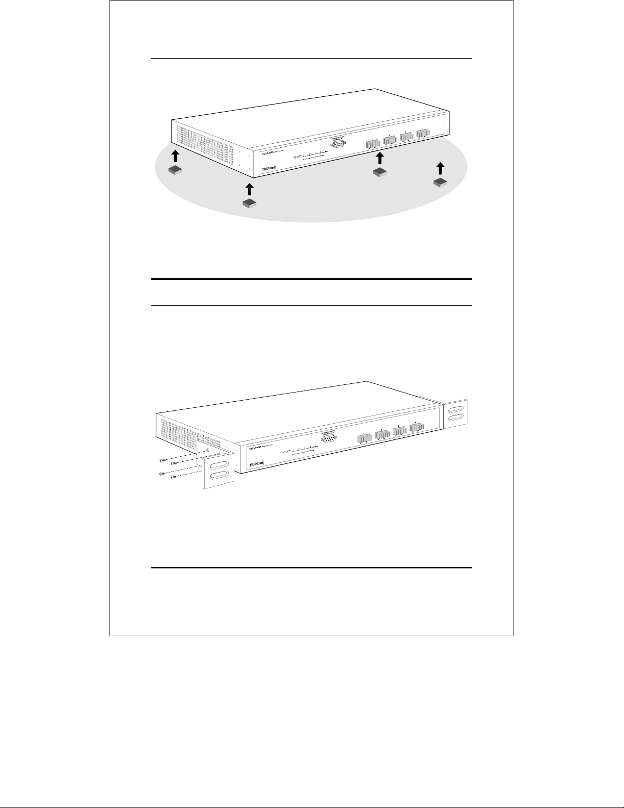
Desktop or Shelf Installation
When installing the Switch on a desktop or shelf, the rubber feet
included with the device must be first attached. Attach these
cushioning feet on the bottom at each corner of the device. Allow
enough ventilation space between the device and the objects
around it.
Unpacking and Setup 7
Page 16
Gigabit Ethernet Switch User’s Guide
Figure 2-1. Gigabit Ethernet Switch installed on a Desktop
or Shelf
Rack Installation
The TEG-S40SX can be mounted in an EIA standard size, 19-inch
rack, which can be placed in a wiring closet with other equipment.
To install, attach the mounting brackets on the switch’s front
panel (one on each side) and secure them with the screws provided.
Figure 2- 2A. Attaching the mounting brackets to the
Gigabit Ethernet Switch
8 Unpacking and Setup
Page 17
Gigabit Ethernet Switch User’s Guide
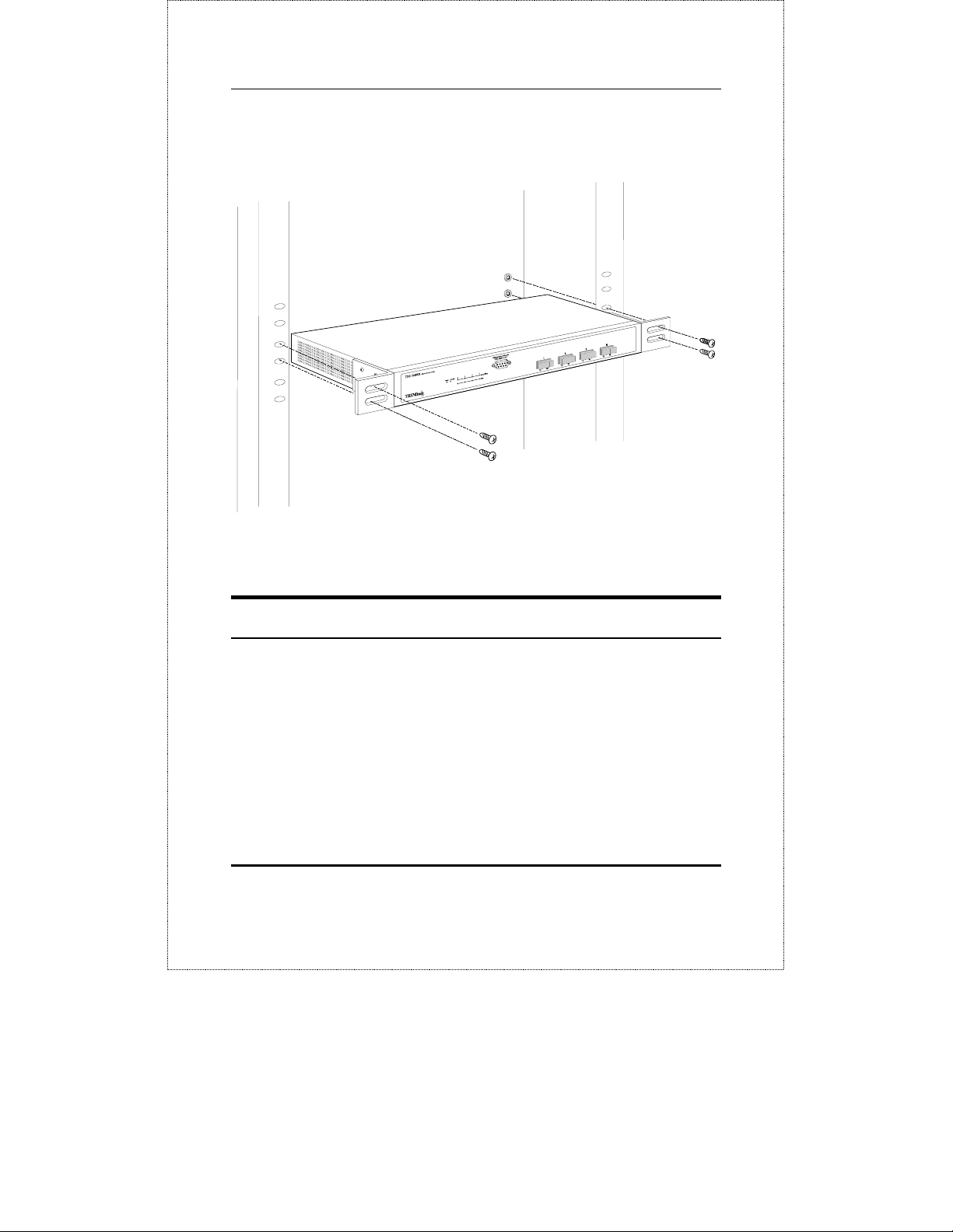
Then, use the screws provided with the equipment rack to mount
the Switch in the rack.
Figure 2-2B. Installing the Gigabit Ethernet Switch in an
equipment rack
Power on
The TEG-S40SX Switch can be used with AC power sources 100 240 VAC, 50 - 60 Hz. The Switch’s power supply will adjust to the
local power source automatically and may be turned on without
having any or all LAN segment cables connected.
After the device is powered on, the LED indicators should respond
as follows:
Unpacking and Setup 9
Page 18

Gigabit Ethernet Switch User’s Guide
♦ The Power LED indicator will light while the Switch loads
onboard software and blinks when performing a self-test.
♦ The Console LED indicator will remain ON if there is a
connection at the RS-232 port, otherwise this LED indicator
is OFF.
Power Failure
As a precaution, the Switch should be unplugged in case of power
failure. When power is resumed, plug the Switch back in.
10 Unpacking and Setup
Page 19
Gigabit Ethernet Switch User’s Guide
3
3 IDENTIFYING
EXTERNAL
COMPONENTS
This chapter describes the front panel, rear panel and LED
indicators of the Switch
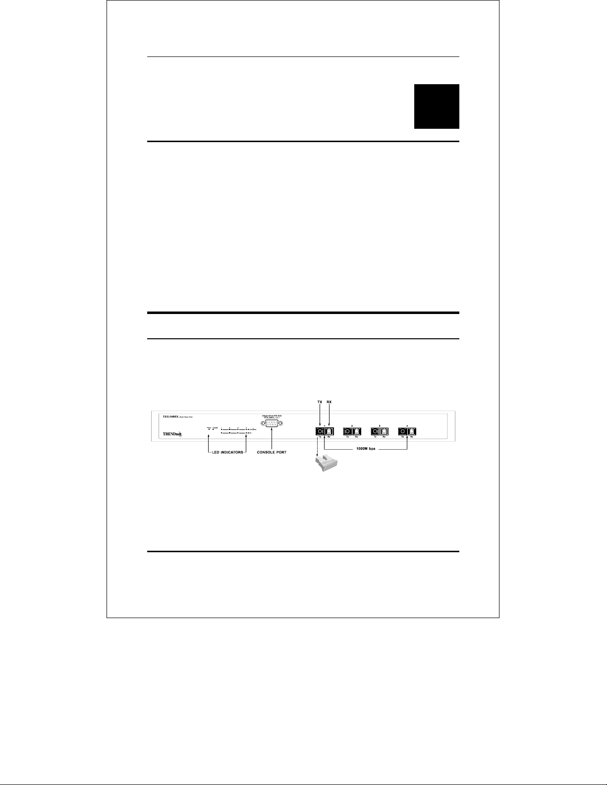
Front Panel
The front panel of the Switch consists of 4 1000BASE-SX multimode fiber ports, an RS-232 communication port, and LED
indicators.
Figure 3-1. Front panel view of the TEG-S40SX Switch
♦ Four Gigabit Ethernet ports of fixed 1000BASE-SX multi-
mode fiber interface.
Identifying External Components 11
Page 20
Gigabit Ethernet Switch User’s Guide
♦ RS-232 DCE console port for diagnosing the Switch via a
connection to a PC and Local Console Management.
♦ Comprehensive LED indicators that display the conditions of
the Switch and status of the network. A description of these
LED indicators follows (see LED Indicators).
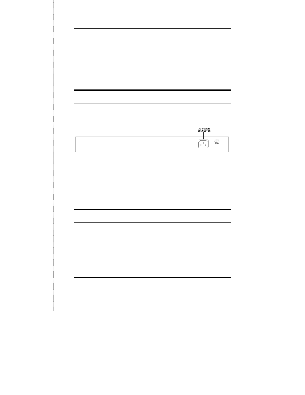
Rear Panel
The rear panel of the Switch consists of an AC power connector.
The following shows the rear panel of the Switch.
Figure 3-2. Rear panel view of the TEG-S40SX
♦ AC Power Connector This is a three-pronged connector
that supports the power cord. Plug in the female connector of
the provided power cord into this connector, and the male
into a power outlet. Supported input voltages range from
100 ~ 240 VAC at 50 ~ 60 Hz.
Right Side Panel
The right side panel of the Switch contains two system fans. The
following shows the right side panel of the Switch.
12 Identifying External Components
Page 21
Gigabit Ethernet Switch User’s Guide
Figure 3-3. Right side panel view of the TEG-S40SX
♦ System Fans These fans are used to dissipate heat. The
sides of the system also provide heat vents to serve the same
purpose. Do not block these openings, and leave adequate
space at the rear and sides of the Switch for proper
ventilation. Be reminded that without proper heat
dissipation and air circulation, system components might
overheat, which could lead to system failure.
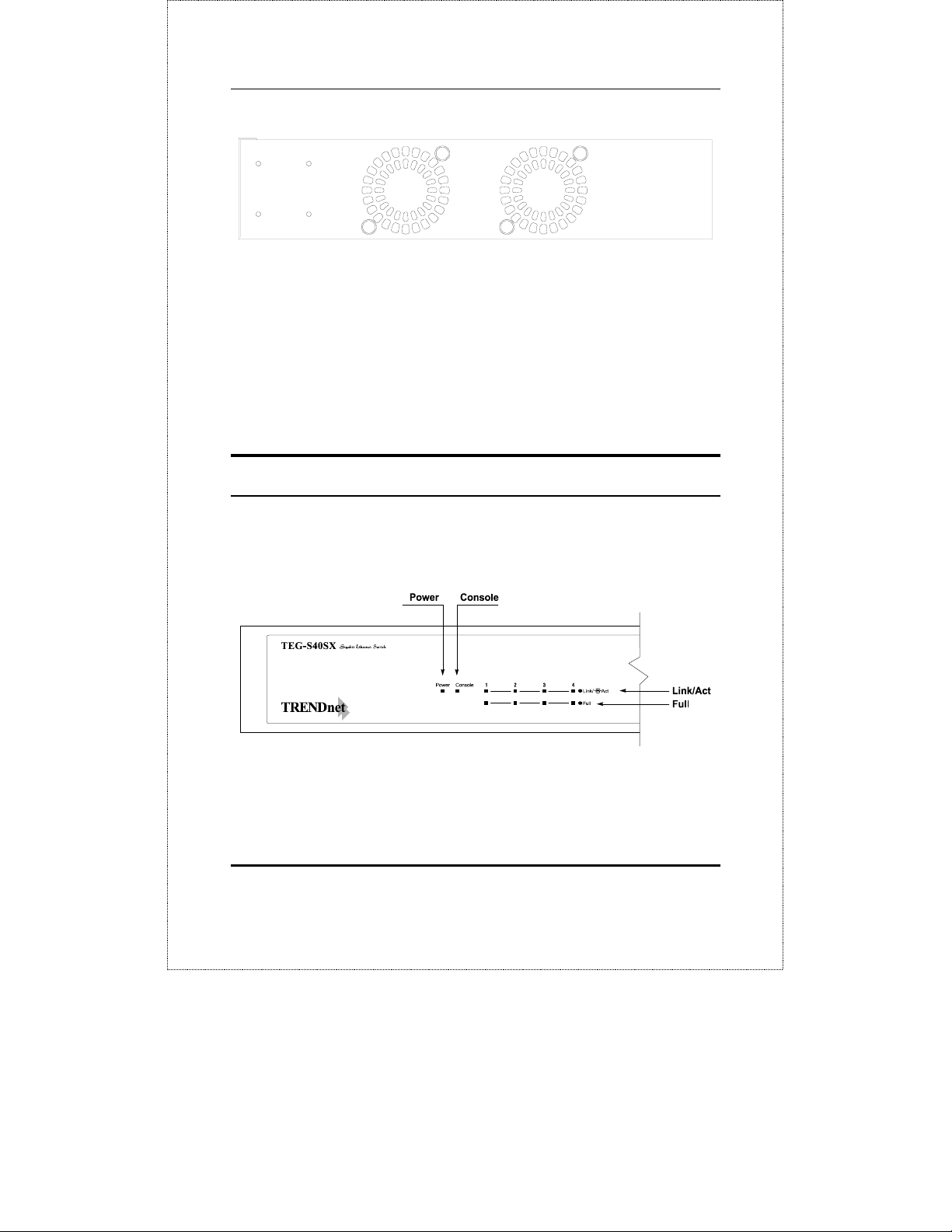
LED Indicators
The LED indicators of the Switch include Power, Console,
Link/Act, and Full. The following shows the LED indicators for the
Switch along with an explanation of each indicator.
Figure 3-3. The TEG-S40SX Switch LED indicators
♦ Power After turning on the power, the Power indicator on
the front panel should light to indicate the Switch is loading
Identifying External Components 13
Page 22

Gigabit Ethernet Switch User’s Guide
onboard software and then begins to blink when performing
a self-test. After approximately 2 seconds, the LED light
again to indicate the ready state of the switch.
♦ Console This LED indicator is lit when the switch is being
managed via out-of-band/local console management through
the RS-232 console port using a straight-through serial
cable. When a secured connection is established, this LED
indicator is lit. Otherwise, it is OFF.
♦ Link/Act. These LED indicators are lighted up when there
is a secure connection (or link) to a device at any of the ports.
The LED indicators blink whenever there is reception or
transmission (i.e. Activity--Act) of data occurring at a port.
♦ Full These LED indicators are illuminated when a port is
operating in full-duplex mode.
14 Identifying External Components
Page 23
Gigabit Ethernet Switch User’s Guide
4
4 CONNECTING THE
SWITCH
This chapter describes how to connect the TEG-S40SX to your
Gigabit Ethernet network.
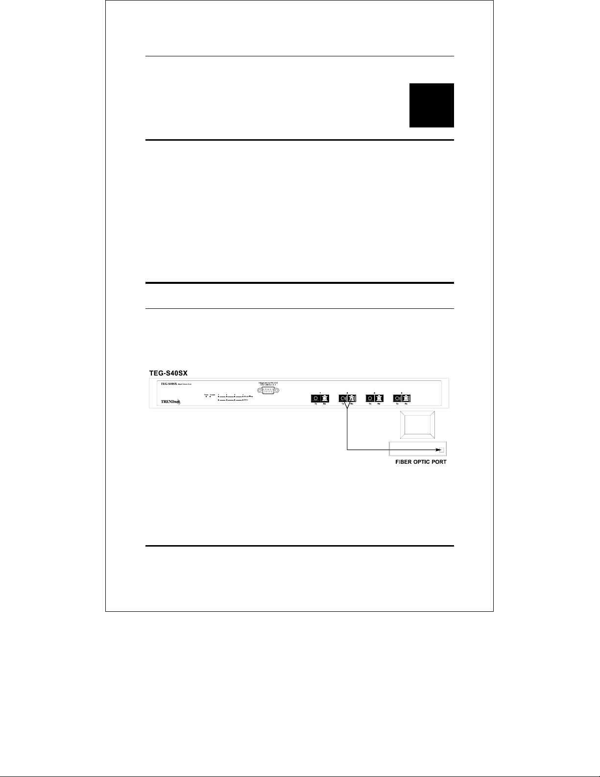
PC to Switch
A PC can be connected to the Switch via a fiber optic cable. The PC
should be connected to any of the four ports (1x - 4x) of the TEGS40SX.
Figure 4-1. TEG-S40SX Switch connected to a PC or
Workstation (full-duplex mode is required)
The LED indicators for PC connection are dependent on the LAN
card capabilities. If LED indicators are not illuminated after
Connecting The Switch 15
Page 24
Gigabit Ethernet Switch User’s Guide
making a proper connection, check the PC’s LAN card, the cable,
Switch conditions, and connections.
The following are LED indicator possibilities for a PC to Switch
connection:
♦ The Link/Act LED indicator lights up upon hookup.
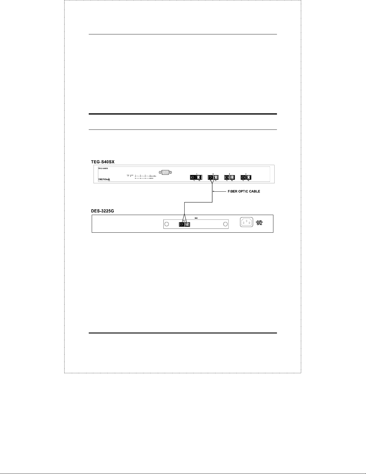
Switch to Switch (other devices)
The Switch can be connected to another switch or other devices
(routers, bridges, etc.) via a fiber optic cable.
Figure 4-2. TEG-S40SX Switch to switch connection
16 Connecting The Switch
Page 25

Gigabit Ethernet Switch User’s Guide
5
5 SWITCH MANAGEMENT
Local Console Management
Local console management involves the administration of the
TEG-S40SX Switch via a direct connection to the RS-232 DCE
console port. From the Main Menu screen of the console program,
an Administrator or Normal User (defined in the next chapter) has
privilege and access to manage, control and monitor the many
functions of the Switch.
The components of the Switch allow them to be part of a
manageable network. These components include a CPU, memory
for data storage, other related hardware, and the SNMP agent
firmware. Activities on the Switch can be monitored with these
components, while the Switch can be manipulated to carry out
specific tasks.
Out-of-Band Management for the Switch is accomplished through
a locally connected management terminal to the RS-232 console
port. Through this port, a user can set up, monitor, or change the
configuration of the Switch.
The Spanning Tree Algorithm (STA) provides the capability for the
Switch to operate properly with other Bridges in a SNMP network
supporting the STA. Using the STA, the network will prevent
Switch Management 17
Page 26

Gigabit Ethernet Switch User’s Guide
network loop, and automatically establish and activate a backup
path in the event of a path failure.
Console port (RS-232 DCE)
Out-of-band management requires connecting a PC (with a SNMP
management platform) to the RS-232 DCE console port of the
Switch. Switch management using terminal emulation/VT100
when connected to the RS-232 DCE console port is called Local
Console Management to differentiate it from management done via
management platforms.
The console port is set for the following configuration:
◊ Baud rate: 9,600
◊ Parity: none
◊ Data width: 8 bits
◊ Stop bits: 1
IP Addresses and SNMP Community
Names
Each Switch has its own IP Address, which is used for
communication with an SNMP network manager or other TCP/IP
application (for example BOOTP, TFTP). You can change the
default Switch IP Address to meet the specification of your
networking address scheme.
In addition, you can also set in the Switch an IP Address for a
gateway or a router. It is useful when the network management
station is not located on the same network as the Switch, making it
necessary for the Switch to go through a gateway or router to
reach the network manager.
18 Switch Management
Page 27

Gigabit Ethernet Switch User’s Guide
For security, you can set in the Switch a list of IP Addresses of the
network managers that you allow to manage the Switch. You can
also change the default Community Name in the Switch and set
access rights of these Community Names.
Traps
Trap managers are special users of the network who are given
certain rights and access in overseeing the maintenance of the
network. Trap managers can receive traps sent from the Switch;
they must immediately take certain actions to avoid future failure
or breakdown of the network.
Traps are messages that alert you of events that occur on the
Switch. The events can be as serious as a reboot (someone
accidentally turned OFF the Switch), or less serious like a port
status change. The Switch generates traps and sends them to the
network manager (trap managers). The following lists the types of
events that can take place on the Switch.
◊ System resets
◊ Errors
◊ Status changes
◊ Topology changes
◊ Operation
You can also specify which network managers may receive traps
from the Switch by setting a list of IP Addresses of the authorized
network managers.
The following are trap types a trap manager will receive:
♦ Cold Start This trap signifies that the Switch has been
powered up and initialized such that software settings are
Switch Management 19
Page 28

Gigabit Ethernet Switch User’s Guide
reconfigured and hardware systems are rebooted. A cold
start is different from a factory reset.
♦ Warm Start This trap signifies that the Switch has been
rebooted, however the POST (Power On Self-Test) is skipped.
♦ Authentication Failure This trap signifies that an
addressee (or manager/ user) on the Switch is not a valid
user of the Switch and may have entered an incorrect
community name.
♦ New Root This trap indicates that the Switch has become
the new root of the Spanning Tree, the trap is sent by a
bridge soon after its election as the new root. This implies
that upon expiration of the Topology Change Timer the new
root trap is sent out immediately after the Switch’s selection
as a new root.
♦ Topology Change A Topology Change trap is sent by the
Switch when any of its configured ports transitions from the
Learning state to the Forwarding state, or from the
Forwarding state to the Blocking state. The trap is not sent
if a new root trap is sent for the same transition.
♦ Link Change Event This trap is sent whenever the link of
a port changes from link up to link down or from link down
to link up.
MIBs
The information stored in the Switch is known as the Management
Information Base (MIB). The Switch uses the standard MIB-II
Management Information Base module. Consequently, MIB values
inside the Switch can be retrieved from any SNMP-based network
manager. In addition to the standard MIB-II, the Switch also
supports its own proprietary enterprise MIB as an extended
Management Information Base. These MIBs may also be retrieved
20 Switch Management
Page 29

Gigabit Ethernet Switch User’s Guide
by specifying the MIB’s Object-Identity (OID) at the network
manager. MIB values can be either read-only or read-write.
Read-only MIBs variables can be either constants that are
programmed into the Switch, or variables that change while the
Switch is in operation. Examples of read-only constants are the
number of ports and types of ports. Examples of read-only
variables are the statistics counters such as the number of errors
that have occurred, or how many kilobytes of data have been
received and forwarded through a port.
Read-write MIBs are variables usually related to user-customized
configurations. Examples of these are the Switch’s IP Address,
Spanning Tree Algorithm parameters, and port status.
If you use a third-party vendors’ SNMP software to manage the
Switch, a diskette listing the Switch’s propriety enterprise MIBs
can be obtained by request. If your software provides functions to
browse or modify MIBs, you can also get the MIB values and
change them (if the MIBs’ attributes permit the write operation).
This process however can be quite involved, since you must know
the MIB OIDs and retrieve them one by one.
Packet Forwarding
The Switch looks at the network configuration to forward packets.
This reduces the traffic congestion on the network, because
packets, instead of being transmitted to all segments, are
transmitted to the destination only. Example: if Port 1 receives a
packet destined for Port 2, the Switch transmits that packet
through Port 2 only, and transmits nothing through Port 1.
♦ Filtering Database A Switch filters frames, i.e., does not
relay frames received by a Switch Port to other Ports on that
Switch, in order to prevent the duplication of frames.
Frames transmitted between a pair of end stations can be
Switch Management 21
Page 30

Gigabit Ethernet Switch User’s Guide
confined to LANs that form a path between those end
stations.
The functions that support the use and maintenance of
filtering database information are:
1. Permanent configuration of reserved addresses.
2. Explicit configuration of static filtering information.
3. Automatic learning of dynamic filtering information through
observation of Switched Local Area Network traffic.
4. Aging out of filtering information that has been
automatically learned.
5. Calculation and configuration of Switched Local Area
Network topology.
Aging Time
The Aging Time is a parameter that affects the auto-learn process
of the Switch in terms of the network configuration. Dynamic
Entries, which make up the auto-learned-node address, are aged
out of the address table according to the Aging Time that you set.
The Aging Time can be from 1 to 99 minutes. A very long Aging
Time can result with the out-of-date Dynamic Entries that may
cause incorrect packet filtering/forwarding decisions.
In the opposite case, if the Aging Time is too short, many entries
may be aged out soon, resulting in a high percentage of received
packets whose source addresses cannot be found in the address
table.
22 Switch Management
Page 31

Gigabit Ethernet Switch User’s Guide
Spanning Tree Algorithm
The Spanning Tree Algorithm (STA) in the Switch allows you to
create alternative paths (with multiple switches or other types of
bridges) in your network. These backup paths are idle until the
Switch determines that a problem has developed in the primary
paths. When a primary path is lost, the switch providing the
alternative path will automatically go into service with no operator
intervention. This automatic network reconfiguration provides
maximum uptime to network users. The concept of the Spanning
Tree Algorithm is a complicated and complex subject and must be
fully researched and understood. Please read the following before
making any changes.
♦ Network loop detection and prevention With STA,
there will be only one path between any two LANs. If there
is more than one path, forwarded packets will loop
indefinitely. STA detects any looped path and selects the
path with the lowest path cost as the active path, while
blocking the other path and using it as the backup path.
♦ Automatic topology re-configuration When the path
for which there is a backup path fails, the backup path will
be automatically activated, and STA will automatically reconfigure the network topology.
STA Operation Levels
STA operates on two levels: the bridge level and the port level. On
the bridge level, STA calculates the Bridge Identifier for each
Switch, then sets the Root Bridge and the Designated Bridges. On
the port level, STA sets the Root Port and Designated Ports.
Details are as follows:
Switch Management 23
Page 32

Gigabit Ethernet Switch User’s Guide
On the Bridge Level
♦ Root Bridge The switch with the lowest Bridge Identifier
is the Root Bridge. Naturally, you will want the Root Bridge
to be the best switch among the switches in the loop to
ensure the highest network performance and reliability.
♦ Bridge Identifier This is the combination of the Bridge
Priority (a parameter that you can set) and the MAC address
of the switch. Example: 4 00 80 C8 00 01 00, where 4 is the
Bridge Priority. A lower Bridge Identifier results in a higher
priority for the switch, and thus increases it probably of
being selected as the Root Bridge.
♦ Designated Bridge From each LAN segment, the attached
Bridge that has the lowest Root Path Cost to the Root Bridge
is the Designated Bridge. It forwards data packets for that
LAN segment. In cases where all Switches have the same
Root Path Cost, the switch with the lowest Bridge Identifier
becomes the Designated Bridge.
♦ Root Path Cost The Root Path Cost of a switch is the sum
of the Path Cost of the Root Port and the Root Path Costs of
all the switches that the packet goes through. The Root Path
Cost of the Root Bridge is zero.
♦ Bridge Priority This is a parameter that users can set.
The smaller the number you set, the higher the Bridge
Priority is. The higher the Bridge Priority, the better the
chance the Switch will be selected as the Root Bridge.
On the Port Level
♦ Root Port Each switch has a Root Port. This is the port
that has the lowest Path Cost to the Root Bridge. In case
there are several such ports, then the one with the lowest
Port Identifier is the Root Port.
24 Switch Management
Page 33

Gigabit Ethernet Switch User’s Guide
♦ Designated Port This is the port on each Designated
Bridge that is attached to the LAN segment for which the
switch is the Designated Bridge.
♦ Port Priority The smaller this number, the higher the Port
Priority is. With higher Port Priority, the higher the
probability that the port will be selected as the Root Port.
♦ Path Cost This is a changeable parameter and may be
modified according to the STA specification.
User-Changeable Parameters
The factory default setting should cover the majority of
installations. However, it is advisable to keep the default settings
as set at the factory; unless, it is absolutely necessary. The user
changeable parameters in the Switch are as follows:
♦ Bridge Priority A Bridge Priority can be from 0 to 65535.
0 is equal to the highest Bridge Priority.
♦ Bridge Hello Time The Hello Time can be from 1 to 10
seconds. This is the interval between two transmissions of
BPDU packets sent by the Root Bridge to tell all other
Switches that it is indeed the Root Bridge. If you set a Hello
Time for your Switch, and it is not the Root Bridge, the set
Hello Time will be used if and when your Switch becomes
the Root Bridge.
Note that the Hello Time cannot be longer than the Max.
Age. Otherwise, a configuration error will occur.
♦ Bridge Max. Age The Max. Age can be from 6 to 40
seconds. At the end of the Max. Age, if a BPDU has still not
been received from the Root Bridge, your Switch will start
sending its own BPDU to all other Switches for permission
to become the Root Bridge. If it turns out that your Switch
Switch Management 25
Page 34

Gigabit Ethernet Switch User’s Guide
has the lowest Bridge Identifier, it will become the Root
Bridge.
♦ Bridge Forward Delay The Forward Delay can be from 4
to 30 seconds. This is the time any port on the Switch spends
in the listening state while moving from the blocking state to
the forwarding state.
Observe the following formulas when you set the above
parameters:
1. Max. Age = 2 x (Forward Delay - 1 second)
2. Max. Age = 2 x (Hello Time + 1 second)
♦ Port Priority A Port Priority can be from 0 to 255. The
lower the number, the greater the probability the port will
be chosen as the Root Port.
Illustration of STA
A simple illustration of three Bridges (or the Switch) connected in
a loop is depicted in Figure 5-1. In this example, you can anticipate
some major network problems if the STA assistance is not applied.
For instance, if Bridge 1 broadcasts a packet to Bridge 2, Bridge 2
will broadcast it to Bridge 3, and Bridge 3 will broadcast it to
Bridge 1...and so on. The broadcast packet will be passed
indefinitely in a loop, causing a serious network failure.
To alleviate network loop problems, STA can be applied as shown
in Figure 5-2. In this example, STA breaks the loop by blocking the
connection between Bridge 1 and 2. The decision to block a
particular connection is based on the STA calculation of the most
current Bridge and Port settings. Now, if Bridge 1 broadcasts a
packet to Bridge 3, then Bridge 3 will broadcast it to Bridge 2 and
the broadcast will end there.
26 Switch Management
Page 35

Gigabit Ethernet Switch User’s Guide
STA setup can be somewhat complex. Therefore, you are advised to
keep the default factory settings and STA will automatically
assign root bridges/ports and block loop connections. However, if
you need to customize the STA parameters, refer to Table 5-1.
Figure 5-1. Before Applying the STA Rules
Figure 5-2. After Applying the STA Rules
Switch Management 27
Page 36

Gigabit Ethernet Switch User’s Guide
STA parameters Settings Effects Comment
Bridge Priority
Hello Time
Max. Age Time
Forward Delay
Enable / Disable
Port Priority
lower the #,
higher the
priority
Increases chance of
becoming the Root
Bridge
1 - 10 sec. No effect, if not
Root Bridge
6 - 40 sec. Compete for Root
Bridge, if BPDU is
not received
4 - 30 sec. High # delays the
change in state
Avoid, if the switch is
used in workgroup
level of a large network
Never set greater than
Max. Age Time
Avoid low number for
unnecessary reset of
Root Bridge
Max. Age ≤ 2 x
(Forward Delay - 1)
Max. Age ≥ 2 x (Hello
Time + 1)
Port Level STA parameters
Enable /
Disable
Enable or disable
this LAN segment
Disable a port for
security or problem
isolation
lower the #,
higher the
Increases chance of
become Root Port
priority
Table 5-1. User-selective STA parameters
28 Switch Management
Page 37

Gigabit Ethernet Switch User’s Guide
6
6 USING THE CONSOLE
INTERFACE
Your Gigabit Ethernet Switch supports a console management
interface that allows you to set up and control your Switch, either
with an ordinary terminal (or terminal emulator), or over the
network using the TCP/IP TELNET protocol. You can use this
facility to perform many basic network management functions. In
addition, the console program will allow you to set up the Switch
for management using an SNMP-based network management
system. This chapter describes how to use the console interface to
access the Switch, change its settings, and monitor its operation.
Connecting to the Switch
You can use the console interface by connecting the Switch to a
VT100-compatible terminal or a computer running an ordinary
terminal emulator program (e.g., the terminal program included
with the Windows operating system) using an RS-232C serial
cable. Your terminal parameters will need to be set to:
♦ VT-100/ANSI compatible
♦ Arrow keys enabled
Using the Console Interface 29
Page 38

Gigabit Ethernet Switch User’s Guide
♦ 9,600 baud
♦ 8 data bits
♦ No parity
♦ One stop bit
You can also access the same functions over a TELNET interface.
Once you have set an IP address for your Switch, you can use a
TELNET program (in a VT-100 compatible terminal mode) to
access and control the Switch. All of the screens are for the most
part identical, whether accessed from the console port or from a
TELNET interface.
Console Usage Conventions
The console interface makes use of the following conventions:
1. Items in <angle brackets> can be toggled on or off using the
space bar, excepting the entries on the Port Configuration
screen .
2. Items in [square brackets]can be changed by typing in a
new value. You can use the backspace and delete keys to
erase characters behind and in front of the cursor.
3. The up and down arrow keys, the left and right arrow keys,
the tab key and the backspace key, can be used to move
between selected items. It is recommended that you use the
tab key and backspace key for moving around console.
4. Items in UPPERCASE are commands. Moving the selection
to a command and pressing Enter will execute that
command, e.g. SAVE, EXIT, etc.
30 Using the Console Interface
Page 39

Gigabit Ethernet Switch User’s Guide
First Time Connecting To The Switch
The Switch supports user-based security that can allow you to
prevent unauthorized users from accessing the Switch or changing
its settings. This section tells how to log onto the Switch.
Note: The passwords used to access the Switch are case
sensitive; therefore, “S” is not the same as “s.”
When you first connect to the Switch, you will be presented
with the first login screen (shown below). Press Ctrl+R (hold
down the Ctrl key, press the R key, and release both
keys) to call up the screen, if the initial login screen does
not appear. Also Ctrl+R can be used at any time to
refresh the screen.
Figure 6-1. Initial Screen, first time connecting to the Switch
Press Enter (Note: Leave the Username and Password fields
blank). You will see the main menu shown below:
Using the Console Interface 31
Page 40

Gigabit Ethernet Switch User’s Guide
Figure 6-2. Main Menu
The first user automatically gets Administrator privileges
(See Table 6-1). It is recommended to create at least one
Administrator-level user for the Switch.
Steps to Create Administrator or Normal User
Access
From the screen above, move the cursor to User Account
Management and press Enter. The User Account Management
menu appears.
1. Choose Add/Modify User Account from the User Account
Management menu. The Add/Modify User Account menu
appears.
2. Enter the new user name, assign an initial password, and then
confirm the new password. Determine whether the new user
should have Administrator or Normal User privileges. (Use
the space bar to toggle between the two options).
3. Press APPLY to let the user addition take effect.
32 Using the Console Interface
Page 41

Gigabit Ethernet Switch User’s Guide
4. Press Esc. to return to the previous screen or Ctrl+T to go to the
root screen.
5. To see a listing of all user accounts and access levels, press Esc.
Then choose View/Delete User Account. The View/Delete
User Account screen appears.
Administrator and Normal User
Privileges.
There are two levels of user privileges: Administrator and Normal
User. Some menu selections available to users with Administrator
privileges may not be available to Normal Users. The main menus
shown are the menus for the two types of users:
The following table summarizes Administrator and Normal User
privileges:
Menu Administrator Normal User
Configuration Yes Yes, view only.
Network Monitoring Yes Yes, view only.
Community Strings and Trap
Stations
Update Firmware and Configuration
Files
User Account Management
Add/Modify User Account Yes No
View/ Delete User Account Yes No
System Utilities Yes Yes
Factory Reset Yes No
Restart System Yes No
Using the Console Interface 33
Privilege
Yes Yes, view only.
Yes No
Page 42

Gigabit Ethernet Switch User’s Guide
Table 6-1. Administrator and Normal User Privileges
After establishing a User Account with Administrator-level
privileges, press Esc. twice. Then choose the Save Changes menu
(seen below). Pressing any key will return to the main menu. You
are now ready to operate the Switch.
Save Configuration
In order to retain any modifications made in the current session, it
is necessary to choose Save Configuration from the main menu.
The following screen will appear to indicate your new settings
have been processed:
Figure 6-3. Save Configuration screen
Login On The Switch Console By
Registered Users
To log in once you have created a registered user,
34 Using the Console Interface
Page 43

Gigabit Ethernet Switch User’s Guide
1. Type in your Username and press Enter.
2. Type in your Password and press Enter.
3. The main menu screen will be displayed based on your
Administrator or Normal User access level or privilege.
Add/Modify User Account
To add or change your user password:
1. Choose User Account Management from the main menu.
The following User Account Management menu appears:
Figure 6-4. User Account Management menu
2. Choose Add/Modify User Account. The following screen
appears
Using the Console Interface 35
Page 44

Gigabit Ethernet Switch User’s Guide
Figure 6-5. Add/Modify User Account screen
3. Type in your Username and press Enter.
4. If you are a new user, type in the Old Password and press
Enter.
5. Type in the New Password you have chosen, and press
Enter. Type in the same new password in the following field
to verify that you have not mistyped it.
6. Determine whether the new user should have Normal User
or Administrator privileges.
7. Choose the APPLY command to let the password change
take effect.
This method can also be used by an Administrator-level user to
change another user’s password.
36 Using the Console Interface
Page 45

Gigabit Ethernet Switch User’s Guide
View/Delete User Account
Access to the console, whether using the console port or via
TELNET, is controlled using a user name and password. Up to
three user names can be defined. The console interface will not let
you delete the current logged-in user, however, in order to prevent
accidentally deleting all of the users with Administrator privilege.
Only users with the Administrator privilege can delete users.
To view your user password:
Choose View/Delete User Account from the User Account
Management menu. The following screen appears:
Figure 6-6. View/Delete User Account screen
To delete your user password:
1. Toggle the Delete field of the user you wish to remove to Yes.
2. Press APPLY to let the user deletion take effect.
Using the Console Interface 37
Page 46

Gigabit Ethernet Switch User’s Guide
Setting Up The Switch
This section will help prepare the Switch user by describing the
System Configuration, Firmware and Configuration
Update, System Utilities, and SNMP Configuration menus
and their respective sub-menus.
System Configuration
Choose System Configuration to access the first item on the
TEG-S40SX main menu. The following menu appears:
Figure 6-7. System Configuration menu
You will need to change some settings to allow you to be able to
manage the Switch from an SNMP-based Network Management
System such as SNMP v1 or to be able to access the Switch using
the TELNET protocol. See the next chapter for Web-based network
management information.
38 Using the Console Interface
Page 47

Gigabit Ethernet Switch User’s Guide
Configure IP Address
The Switch needs to have a TCP/IP address assigned to it so that
the network management system or TELNET client can find it on
the network. The IP Configuration screen allows you to change
the settings for the two different interfaces used on the Switch: the
Ethernet interface used for in-band communication, and the SLIP
interface used over the console port for out-of-band
communication.
Choose Configure IP Address to access the first item on the
System Configuration menu. The following screen appears:
Figure 6-8. IP Configuration screen
Each of the fields on this screen takes effect the next time the
system is restarted. Fields that can be set include:
♦ BOOTP Service Determines whether the Switch should
send out a BOOTP broadcast request when it is powered up.
The BOOTP protocol allows IP addresses, network masks,
and default gateways to be assigned on a central BOOTP
server; if this option is set the Switch will first look for a
Using the Console Interface 39
Page 48

Gigabit Ethernet Switch User’s Guide
BOOTP server to provide it with this information before
using the supplied settings.
♦ IP Address Determines the IP address used by the Switch
for receiving SNMP and TELNET communications. Should
be of the form xxx.xxx.xxx.xxx, where each xxx is a number
(represented in decimal) between 0 and 255. This address
should be a unique address on a network assigned to you by
the central Internet authorities. The same IP address is
shared by both the SLIP and Ethernet network interfaces.
♦ Subnet Mask Bitmask that determines the extent of the
subnet that the Switch is on. Should be of the form
xxx.xxx.xxx.xxx, where each xxx is a number (represented in
decimal) between 0 and 255. If no subnetting is being done,
the value should be 255.0.0.0 for a Class A network,
255.255.0.0 for a Class B network, and 255.255.255.0 for a
Class C network.
♦ Default Gateway IP address that determines where
frames with a destination outside the current subnet should
be sent. This is usually the address of a router or a host
acting as an IP gateway. If your network is not part of an
internetwork, or you do not want the Switch to be accessible
outside your local network, you can leave this field blank.
Configure Console
You can use the Console Configuration screen to choose
whether to use the Switch’s RS-232C serial port for console
management or for out-of-band TCP/IP communications using
SLIP, and to set the bit rate used for SLIP communications.
Choose Configure Console to access the last item on the System
Configuration menu. The following screen appears:
40 Using the Console Interface
Page 49

Gigabit Ethernet Switch User’s Guide
Figure 6-9. Console Configuration screen
The following fields can be set:
Restart Setting:
♦ Console Timeout This setting for the restart of the console
is 15 mins, 30 mins, 45 mins, 60 mins, or Never.
♦ Serial Port Determines whether the serial port should be
used for out-of-band (SLIP) management or for console
management, starting from the next time the Switch is
restarted. In this field, you can toggle between SLIP or
Console port type settings.
♦ Baud Rate Determines the serial port bit rate that will be
used the next time the Switch is restarted. Applies only
when the serial port is being used for out-of-band (SLIP)
management; it does not apply when the port is used for the
console port. Available speeds are 2400, 9600, 19,200 and
38,400 bits per second. The default setting in this Switch
version is 9600.
Using the Console Interface 41
Page 50

Gigabit Ethernet Switch User’s Guide
Configure Switch
The Switch Configuration screen shows various pieces of
information about your Switch, and allows you to set the System
Name, System Location, and System Contact. These settings
can be retrieved from the Switch using SNMP requests, allowing
these settings to be used for network management purposes.
Choose Configure Switch to access the second item on the
System Configuration menu. The following screen appears:
Figure 6-10. Switch Configuration screen
The fields you can set are:
♦ System Name Corresponds to the SNMP MIB II variable
system.sysName, and is used to give a name to the
Switch for administrative purposes. The Switch’s fully
qualified domain name is often used, provided a name has
been assigned.
♦ System Location Corresponds to the SNMP MIB II
variable
42 Using the Console Interface
system.sysLocation, and is used to indicate
Page 51

Gigabit Ethernet Switch User’s Guide
the physical location of the Switch for administrative
purposes.
♦ System Contact Corresponds to the SNMP MIB II variable
sysContact, and is used to give the name and contact
information for the person responsible for administering the
Switch.
The Configure Advanced Switch Features screen allows you to
enable or disable auto-partitioning on all ports as well as to enable
or disable head of line blocking prevention. Press ADVANCE
SETTINGS on the System Configuration window to access the
Configure Advanced Switch Features screen:
Figure 6-11. Configure Advanced Switch Features screen
The field you can set is:
♦ Head Of Line (HOL) Blocking Prevention If enabled, this
function is designed to prevent forwarding a packet to a
“blocking” port, that is, a port where an excess of packets are
queued up. Note that when a multicast packet or a packet with
an unknown destination address needs
Using the Console Interface 43
Page 52

Gigabit Ethernet Switch User’s Guide
♦ to be forwarded to several ports, and if some of them are
“blocking”, the packet will not be discarded, rather it will be
forwarded only to the ports that are not “blocking”.
Configure Ports
The port configuration screen allows you to change the port state
in the case when you would like to partition a port, or for
observation, device repair, or security reasons. Great caution,
however, must be observed when partitioning a port; you should
make sure that the partitioned port is not being used as the port to
control or monitor the condition of other devices.
To change the configuration of a port:
1. Select System Configuration from the main menu and
then choose Configure Ports. The following screen
appears:
Figure 6-12. Port Configuration screen
2. Specify the port in the Port (1-4) field.
44 Using the Console Interface
Page 53

Gigabit Ethernet Switch User’s Guide
3. In the State field, change the port state to Enabled or
Disabled.
4. In the Flow Ctrl field, toggle Off or On.
5. In the Priority field, select Normal, High or Low.
6. In the Broadcast Storm Rising Action and Broadcast
Storm Falling Action fields, set the desired setting.
7. Press CTRL+S to let the changes take effect.
The Speed/Duplex field reflects the current condition of the
port, 1000M/Full. It is a read-only field and cannot be
changed.
The fields you can set are:
♦ Port (1-4) Select the desired port in this field.
♦ State When you disable the state, the port will be
partitioned from the rest of the network. In this partitioned
state, it will only be able to accept management packets. All
other packets will be dropped.
♦ Flow Ctrl Enables or disables IEEE 802.3x flow control on
the port. Flow control allows the port to send a Pause packet
to a transmitting IEEE 802.3x-compliant device, so that its
buffers don’t overflow and data is not lost.
♦ Priority
Sets the priority for traffic arriving at this port
to high, normal or low. Higher priority packets are processed
first in the switch’s packet queue.
♦ Broadcast Storm Rising Action This setting will be
activated when the switch detects that 80% of packets on the
segment connected to the port are broadcast packets and the
port surpasses 30% utilization. When these criteria are met,
the port can be configured to Do Nothing, Blocking or
Using the Console Interface 45
Page 54

Gigabit Ethernet Switch User’s Guide
Blocking-Trap. The Do Nothing setting causes the switch to
operate normally, in other words, ignore the broadcast storm
condition. The Blocking setting causes the port to drop all
broadcast frames, thus isolating the broadcast storm.
Blocking-Trap performs the same action as Blocking, except
it also sends a trap to the designated Trap Recipient
informing them of the situation.
♦ Broadcast Storm Falling Action This setting will be
activated when a Broadcast Storm Rising Action has
occurred and the switch detects that port utilization has
dropped below 10%. This setting can be configured to Do
Nothing, Forwarding or Forwarding-Trap. The Do Nothing
setting causes the switch to operate normally, in other
words, ignore the situation. If the port had met the
Broadcast Storm Rising Action criteria and started Blocking
broadcast packets, it will continue doing so. The Forwarding
setting causes the port to begin forwarding broadcast
frames, thus removing the Blocking state imposed by the
Broadcast Storm Rising Action. Forwarding-Trap performs
the same action as Forwarding, except it also sends a trap to
the designated Trap Recipient informing them of the
situation.
Configure Port Mirroring
The Port Mirroring Configuration screen allows you to copy
frames transmitted and received on a port and redirect the copies
to another port. You can attach a monitoring device to the
mirrored port, such as a sniffer or an RMON probe, to view details
about the packets passing through the first port. This is useful for
network monitoring and troubleshooting purposes.
Choose Configure Port Mirroring on the System
Configuration menu to access the Port Mirroring
Configuration screen:
46 Using the Console Interface
Page 55

Gigabit Ethernet Switch User’s Guide
Figure 6-13. Port Mirroring Configuration screen
To configure a mirror port, select the port from where you want to
copy frames in the Source Port field. Then select the port which
receives the copies from the source port in the Target Port field.
The target port is where you will connect a
monitoring/troubleshooting device such as a sniffer or an RMON
probe.
Configure Spanning Tree Protocol
The Spanning Tree Algorithm Parameters can be used for creating
alternative paths in your network. The Protocol Parameters allow
you to change the behind the scene parameters of the Spanning
Tree Algorithm at the bridge level. The parameters for this section
have been fully explained in Chapter 5’s Switch Management, see
STA Operation Levels: On the Bridge level, and User-Changeable
Parameters. It is recommended that you read these sections, as
well as the introductory section in the same chapter entitled
Spanning Tree Algorithm before changing any of the parameters.
To change the Protocol Parameters:
Using the Console Interface 47
Page 56

Gigabit Ethernet Switch User’s Guide
1. Choose Configure Spanning Tree Protocol from the
System Configuration menu. The following Spanning
Tree Protocol Configuration menu will be displayed:
Figure 6-14. Spanning Tree Protocol Configuration menu
2. Choose STP Parameters Setting to access the following
screen:
Figure 6-15. STP Parameters Setting screen
48 Using the Console Interface
Page 57

Gigabit Ethernet Switch User’s Guide
3. Change the Disabled setting to Enabled in the Spanning
Tree Protocol field.
4. Enter the Bridge Max Age in the Max Age(6-40 sec) field.
5. Enter the Bridge Hello Time in the Hello Time(1-10 sec)
field.
6. Enter the Bridge Forward Delay time in the Forward
Delay(4-30 sec) field.
7. Enter the Bridge Priority in the Bridge Priority(0-65535)
field.
The information on the screen is described as follows:
♦ Spanning Tree Protocol Select Enabled to implement
the Spanning Tree Protocol.
♦ Time Since Topology Changes(sec) Read-only object
displays the last time changes were made to the network
topology. These changes usually occur when backup paths
are activated due to primary path failures.
♦ Topology Change Count Read-only object displays the
number of times (since the current management session
with the device was started) changes were made to the
network topology. Changes usually occur on the network
when backup paths are activated.
♦ Designated Root Read-only object displays the MAC
(Ethernet) address of the bridge/switch on the network
that has been chosen as the STP root.
♦ Root Cost Read-only object displays the cost for the path
between the switch and the root bridge. If the switch is the
root bridge, then the root cost is zero.
Using the Console Interface 49
Page 58

Gigabit Ethernet Switch User’s Guide
♦ Root Port Read-only object identifies the port (on the
bridge) that offers the least path cost from the bridge to
the root bridge. In the event of a network loop, data
packets will pass through the root port.
♦ Max Age(Sec) Read-only object indicates the maximum
age of STP information learned from the network (on any
port) before it is discarded.
♦ Forward Delay(sec) Read-only object indicates how fast
any port on the bridge can change its spanning state when
moving towards the forwarding state. The value
determines how long the port stays in each of the listening
and learning states, which precede the forwarding state.
♦ Hold Time(Sec) Read-only object displays the time interval
during which no more than two configuration BPDUs shall be
transmitted by the bridge.
♦ Root Priority Read-only object displays the priority
number of the root bridge of the Spanning Tree. The value
is used in conjunction with the bridge MAC address to set
the bridge ID, which in turn is used when determining the
root bridge of a multibridged network. The root bridge is
responsible for processing data packets when network
loops occur. The smaller the number set, the higher the
bridge priority is. The higher the bridge priority, the more
chance the bridge has of becoming the root bridge. A
bridge priority ranges from 0 to 65535, with 0 being the
highest priority.
♦ Max Age(6-40 Sec) Maximum Age is a read-write object
that can be set from 6 to 40 seconds. At the end of the
Maximum Age, if a BPDU has still not been received from
the Root ridge, your Switch will start sending its own
BPDU to all other switches for permission to become the
Root Bridge. If it turns out that your Switch has the
lowest Bridge Identifier, it will become the Root Bridge.
50 Using the Console Interface
Page 59

Gigabit Ethernet Switch User’s Guide
♦ Hello Time(1-10 Sec) Hello Time is a read-write object
that can be set from 1 to 10 seconds. This is the interval
between two transmissions of BPDU packets sent by the
Root Bridge to tell all other switches that it is indeed the
Root Bridge. If you set a Hello Time for your Switch, and it
is not the Root Bridge, the set Hello Time will be used if
and when your Switch becomes the Root Bridge.
♦ Forward Delay(4-30 Sec) The Forward Delay is a read-
write object that can be set from 4 to 30 seconds. This is
the time any port on the Switch spends in the listening
state while moving from the blocking state to the
forwarding state.
♦ Bridge Priority(0-65535 Sec) A Bridge Priority is a
read-write object that can be set from 0 to 65535. This is
the priority number of the bridge. The value is used in
conjunction with the bridge MAC address to set the bridge
ID, which in turn is used when determining the root
bridge of a multibridged network. The root bridge is
responsible for processing data packets when network
loops occur. The smaller the number set, the higher the
bridge priority is. The higher the bridge priority, the more
chance the bridge has of becoming the root bridge. Zero is
the highest priority.
To change the parameters on individual ports:
1. Choose Configure Spanning Tree Protocol from the
System Configuration menu.
2. Choose STP Custom Setting from the Spanning Tree
Protocol Configuration menu. The following screen
appears:
Using the Console Interface 51
Page 60

Gigabit Ethernet Switch User’s Guide
Figure 6-16. STP Custom Setting screen
3. Change the Disabled setting of the STP State field to Enabled.
4. Set the path cost for the port between 1 and 65535 in the Cost
field.
5. Set the priority for the port between 0 and 255 in the Priority
field.
6. Press CTRL+S to apply the new settings.
Configure Forwarding and Filtering Table
When a packet hits the Switch, the Switch looks in the filtering
and forwarding tables to decide what to do with the packet; either
to filter it off the network, or to forward it through the port on
which its destination lies. The Configure Filtering and
Forwarding table screen allows you to stop or start address
learning as well as to select an age-out time of the MAC address in
the selected address table. This screen also permits you to access
two additional configuration screens from the menu at the bottom
of the window.
52 Using the Console Interface
Page 61

Gigabit Ethernet Switch User’s Guide
Choose Configure Forwarding and Filtering Table from the
Switch Configuration menu to access the following screen:
Figure 6-17. Filtering and Forwarding Table Configuration screen
The following fields at the top of the screen can be set:
♦ Lock Address Table(STOPs Learning) Mostly used for
security purposes, when the forwarding table is locked the
Switch will no longer learn the MAC addresses for new hosts. If
your network configuration doesn’t change, locking the
forwarding table helps keep intruders off your network since
any packet coming from an unknown source address will be
dropped by the Switch.
♦ MAC Address Age-out Time Enter the desired MAC address
age-out time in this field (1 to 9999 minutes) .
The Custom Forwarding Table displays a list of manually
defined static MAC address entries.
Using the Console Interface 53
Page 62

Gigabit Ethernet Switch User’s Guide
To access the Custom Forwarding Table, choose Configure
Forwarding and Filtering Table from the System
Configuration menu. Then select Custom Forwarding
Table from the bottom of the Filtering and Forwarding
Table Configuration screen. The following screen appears:
Figure 6-18. Custom Forwarding Table screen
♦ Under the Destination MAC Address heading a total of
ten destination addresses will be seen per page. The Switch
can hold up to 256 entries.
♦ Under the Destination Port heading a port number will be
displayed for each corresponding destination address.
♦ Under the Status heading, the status will be displayed for
each corresponding destination address. The status of the
MAC address should show “in use”.
By mapping a port to a destination MAC address, the switch can
permanently forward traffic to the specified device, even after long
periods of network inactivity or during times of network
congestion.
54 Using the Console Interface
Page 63

Gigabit Ethernet Switch User’s Guide
To make a change to the Custom Forwarding Table, choose
either Add or Remove in the Action field. Then enter the MAC
Address, the Port number that permanently forwards traffic
from the specified device, regardless of the device’s network
activity or current network congestion, and press APPLY.
The Custom Filtering Table contains filtering information
configured into the Switch by (local or network) management
specifying the set of ports to which packets received from specific
ports and containing specific destination addresses are not allowed
to be forwarded. You can use the Custom Filtering Table for
network security purposes thereby discarding unwanted addresses
from the Forwarding Table.
Dynamic Filtering and Static Filtering are among the two
important features of the Custom Filtering Table. They are
defined here briefly as follows. Dynamic Filtering is defined when
a dynamic entry is created by the Learning Process as a result of
observation of network traffic in the Filtering Database. Static
Filtering is defined as static entries that may be added and
removed from the Filtering Database by the user. They are not
automatically removed by any timeout mechanism.
To access the Custom Filtering Table, select Configure
Forwarding and Filtering Table from the System
Configuration menu. Then select Custom Filtering Table
from the bottom of the Filtering and Forwarding Table
Configuration screen. The following screen appears:
Using the Console Interface 55
Page 64

Gigabit Ethernet Switch User’s Guide
Figure 6-19. Custom Filtering Table screen
To make a change to the Custom Filtering Table, choose AddFilter-Both or Remove in the Action field. Then enter the MAC
Address and press APPLY.
Firmware and Configuration Update
The Switch is capable of obtaining its boot-time configuration
information, as well as updated versions of its internal firmware,
using TFTP (the Trivial File Transfer Protocol) and BOOTP (the
BOOTstrap Protocol). You can use the Firmware and
Configuration Update screen to control this feature.
Choose Firmware and Configuration Update on the Switch’s
main menu. The following screen appears:
56 Using the Console Interface
Page 65

Gigabit Ethernet Switch User’s Guide
Figure 6-20. Firmware and Configuration Update screen
The fields you can set are:
♦ Software Update Mode Set to either Network or SLIP.
Determines whether the configuration file should be
obtained through the Ethernet network or through the
console port.
♦ TFTP Server Address The IP address of the TFTP server
where the configuration file is located. This entry is used
only if the Firmware Update is set to Enabled. If BOOTP
Service (see the IP Configuration screen under Configure
IP Address on the System Configuration menu) is set to
Enabled, the address will be obtained from the BOOTP
server.
♦ Firmware Update Determines whether or not the Switch
will try to look for a runtime image file over the network. If
set to Disabled, none of the fields below have any effect.
♦ File Name The pathname of the runtime image file on your
TFTP server to be downloaded.
Using the Console Interface 57
Page 66

Gigabit Ethernet Switch User’s Guide
♦ Use Config File Toggle to Enabled to download config file
during reboot.
♦ Config File Name The name of the configuration file to be
downloaded.
System Utilities
The System Utilities menu features a Ping Test option. This
sends a Ping to test network connectivity between the Switch and
any other network device with an IP address.
Choose System Utilities on the main menu to access the System
Utilities menu seen below.
Figure 6-21. System Utilities menu
Choose Ping Test to access the following screen:
58 Using the Console Interface
Page 67

Gigabit Ethernet Switch User’s Guide
Figure 6-22. Ping Test screen
The fields you can set are:
♦ Destination IP Address The IP address to be Pinged.
♦ Repetition Amount of times the Switch should send the Ping
(1-255). If zero is chosen, the Switch will continue Pinging
indefinitely.
In the lower part of the Ping Test screen, you can view the Ping
status, including Result, Reply, Time out, and Unreachable.
SNMP Configuration
The Switch sends out SNMP traps to network management
stations whenever certain exceptional events occur, such as when
the Switch is turned on or when a system reset occurs. The Switch
allows traps to be routed to up to four different network
management hosts.
For a detail list of Trap Types used for this Switch, see Chapter 5,
Switch Management, Traps section.
Using the Console Interface 59
Page 68

Gigabit Ethernet Switch User’s Guide
SNMP (version 1) implements a rudimentary form of security by
requiring that each request include a community name. A
community name is an arbitrary string of characters used as a
“password” to control access to the Switch. If the Switch receives a
request with a community name it does not recognize, it will
trigger an authentication trap.
The SNMP allows up to four different community names to be
defined. The community name
public is defined by default; you
can change this name in addition to adding others. You will need
to coordinate these names with the community name settings you
use in your network management system.
Choose SNMP Configuration from the main menu to access the
following screen:
Figure 6-23. SNMP Configuration screen
The following parameters can be set:
♦ Community String/SNMP Community String
Determines the community name to be included in the trap
request.
60 Using the Console Interface
Page 69

Gigabit Ethernet Switch User’s Guide
♦ Access Right Allows each community to be separately set
to either Read Only or Read/Write.
♦ Status Determines whether this community name entry is
Valid or Invalid. An entry can be deleted by changing its
status to Invalid.
♦ IP Address The IP address of the network management
station to receive the trap.
Switch Monitoring
The Switch allows you to keep statistics on the operation of each
port. The statistics obtained can be used to monitor the conditions
and general efficiency of the Switch.
Network Monitoring
This display permits you to observe the condition of each
individual port.
Traffic Statistics
To display the Port Utilization table:
1. Choose Network Monitoring from the main menu.
2. Choose Traffic Statistics from the Network Monitoring
menu.
3. Choose Port Utilization from the Traffic Statistics menu.
Using the Console Interface 61
Page 70

Gigabit Ethernet Switch User’s Guide
Figure 6-24. Port Utilization screen
The information displayed above includes:
♦ Update Interval Select the desired update increment setting
from: 1 sec, 5 sec, 15 sec, 30 sec, 1 min, or Suspend.
♦ TX/sec The number of good bytes sent from the respective port
per second.
♦ RX/sec The number of good bytes received per second. This
also includes local and dropped packets.
♦ %Util. This shows the percentage of available bandwidth each
port is using over the amount of time specified by the update
interval.
To display the Port Traffic Statistics table:
1. Choose Network Monitoring from the main menu.
2. Choose Traffic Statistics from the Network Monitoring
menu.
62 Using the Console Interface
Page 71

Gigabit Ethernet Switch User’s Guide
3. Choose Port Traffic Statistics from the Traffic
Statistics menu.
Figure 6-25. Port Traffic Statistics screen
The information displayed above includes:
♦ Ports This field always displays “1 to 4” in this 4-port Switch
version.
♦ Update Interval Select the desired update increment setting
from: 1 sec, 5 sec, 15 sec, 30 sec, 1 min, or Suspend.
♦ Speed The speed for each port is 1000M. When a link is up
“1000M/Full” will be displayed. When a link is down “–“ will be
displayed.
♦ % Utilization This shows the percentage of available
bandwidth each port is using over the amount of time specified
by the update interval.
♦ Bytes Recv. The number of good bytes received. This also
includes local and dropped packets.
Using the Console Interface 63
Page 72

Gigabit Ethernet Switch User’s Guide
♦ Bytes Sent The number of good bytes sent from the respective
port.
♦ Frames Recv. The number of good frames received. This also
includes local and dropped packets.
♦ Frames Sent The number of good frames sent from the
respective port.
♦ Total Bytes Recv. The number of bytes received, good and
bad.
♦ Total Frames Recv. The number of frames received, good and
bad.
♦ Last Seen MAC The MAC address of the device where the
port information was most recently accessed.
To display the Port Error Packet Statistics table:
1. Choose Network Monitoring from the main menu.
2. Choose Traffic Statistics from the Network Monitoring
menu.
3. Choose Port Error Packet Statistics from the Traffic
Statistics menu.
64 Using the Console Interface
Page 73

Gigabit Ethernet Switch User’s Guide
Figure 6-26. Port Error Packet Statistics table
The information displayed above includes:
♦ Ports This field always displays “1 to 4” in this 4-port Switch
version.
♦ Update Interval Select the desired update increment setting
from: 1 sec, 5 sec, 15 sec, 30 sec, 1 min, or Suspend.
♦ CRC Errors The number of frames that fail the CRC
integrity check.
♦ Oversize Frames The number of good frames with length
greater than 1518 bytes and therefore are greater than the
maximum legal length.
♦ Fragments The number of packets less than 64 bytes with
either bad framing or an invalid CRC. These are normally
the result of collisions.
♦ Jabbers The number of frames with length more than 1518
bytes and with CRC error or misalignment (bad framing).
Using the Console Interface 65
Page 74

Gigabit Ethernet Switch User’s Guide
♦ Late Collisions The number of collisions that occur at or
after the 64
th
byte (octet) in the frame.
♦ Mac Rx Errors The number of frames with received MAC
Errors.
♦ Dropped Frames Counts received packets which are
dropped due to any of the following reasons: lack of available
receive buffers, port-disable, link-test-fail, spanning tree, or
empty distribution list.
♦ Total errors The sum of the CRC Errors, Oversize Frames,
Fragments, Jabbers, Late Collisions, Mac Rx Errors, and
Dropped Frames counters.
♦ Collisions The number of collision errors.
To display the Port Packet Analysis Statistics table:
1. Choose Network Monitoring from the main menu.
2. Choose Traffic Statistics from the Network Monitoring
menu.
3. Choose Port Packet Analysis Statistics from the Traffic
Statistics menu.
66 Using the Console Interface
Page 75

Gigabit Ethernet Switch User’s Guide
Figure 6-27. Port Packet Analysis Statistics table
The information displayed above includes:
♦ Port Enter the desired port in this field.
♦ Update Interval Select the desired update increment setting
from: 1 sec, 5 sec, 15 sec, 30 sec, 1 min, or Suspend.
♦ 64, 65-127, 128-255, 256-511, 512-1023, 1024-1518 The
number of good frames of various length ranges, both valid
and invalid.
♦ RX (GOOD) The number of good frames received. This also
includes local and dropped packets.
♦ TX (GOOD) The number of good frames sent from the
respective port.
♦ Total RX The number of frames received, good and bad.
♦ TX Octets The number of good bytes sent from the
respective port.
Using the Console Interface 67
Page 76

Gigabit Ethernet Switch User’s Guide
♦ RX Octets The number of good bytes received. This also
includes local and dropped packets.
♦ Total RX The number of bytes received, good and bad.
♦ Unicast RX/Unicast TX The number of good unicast
frames received and sent. This includes dropped unicast
packets.
♦ Multicast RX/Multicast TX The number of good multicast
frames received and sent. This includes local and dropped
multicast packets.
♦ Broadcast RX/Broadcast TX The number of good
broadcast frames received and sent. This includes dropped
broadcast packets.
Forwarding Table
The Forwarding Table allows the user to view which Switch
port(s) a specific network device uses to communicate on the
network. You can sort this table by MAC address or port. This is
useful for viewing which ports one device is using, or which devices
are using one port.
To display the Forwarding Table,
1. Choose Network Monitoring from the main menu.
2. Choose Forwarding Table from the Network Monitoring
menu.
68 Using the Console Interface
Page 77

Gigabit Ethernet Switch User’s Guide
Figure 6-28. Forwarding Table
To browse by MAC address, select MAC address in the Search by
field, enter the desired MAC address in the next field, and then
press FIND.
To browse by port number, select Port in the Search by field,
enter the desired port in the next field, and then press FIND.
A forwarding table containing Port, MAC Address, and Learned
status is located on the lower part of the screen.
Resetting the Switch
You can use the console interface to reset the Switch, either doing
a Restart System (which restarts the Switch and is identical to
powering the Switch off and back on again) or a Factory Reset to
Default Value (which sets all of the Switch’s parameters to what
they were when the Switch was delivered from the factory).
Using the Console Interface 69
Page 78

Gigabit Ethernet Switch User’s Guide
Restart System
To perform a system reset, choose Restart System from the main
menu. Please note there is no confirmation query before the
system is rebooted.
Figure 6-29. Restart System screen
Factory Reset to Default Value
Before performing a factory reset, be absolutely certain that this is
what you want to do. Once the reset is done, all of the Switch’s
settings stored in NV-RAM (including TCP/IP parameters, SNMP
parameters, the enabled/disabled settings of ports, security
settings, etc.) will be erased and restored to their factory default
settings.
1. Choose Factory Reset to Default Value from the main
menu. The following screen appears:
70 Using the Console Interface
Page 79

Gigabit Ethernet Switch User’s Guide
Figure 6-30. Factory Reset to Default Value screen
2. Move the cursor to Yes to confirm the reset and press Enter.
The main menu screen should appear.
Logout
To exit the Switch, choose Logout from the main menu. You will
be returned to the opening login screen.
Using the Console Interface 71
Page 80

Page 81

Gigabit Ethernet Switch User’s Guide
7
7 WEB-BASED
NETWORK
MANAGEMENT
Introduction
The TEG-S40SX offers an embedded Web-based (hypertext)
interface allowing users to manage the Switch from
anywhere on the network through a standard browser such
as Netscape Navigator/Communicator or Microsoft Internet
Explorer. The Web browser acts as a universal access tool
and can communicate directly with the Switch using HTTP
protocol. Your browser screen may vary with the screen shots
(pictures) in this guide.
NOTE: This Web-based Network Management module
does not accept Chinese language input (or other
languages requiring 2 bytes per character).
Web-Based Network Management 73
Page 82

Gigabit Ethernet Switch User’s Guide
Getting Started
The first step in getting started in using Web-based
management for your Switch is to secure a browser. A Web
browser is a program which allows a person to read
hypertext, for example, Netscape Navigator or Microsoft
Internet Explorer. Follow the installation instructions for the
browser.
The second and last step is to configure the IP interface of the
Switch. This can be done manually through a console (see the
Configure IP Address section in the “Using The Console
Interface” chapter).
Management
To begin managing your Switch simply run the browser you
have installed on your computer and open the IP address you
have defined for the device.
In the page that opens, click on the Login to TEG-S40SX
Manager hyperlink. This opens the main page in the
management module.
The top portion of the window contains an interactive view of
the Switch’s front panel. Clicking on one of the four ports
opens a configuration window for that particular port.
The main page contains a window along the left-hand side
with a column of buttons labeled: Configuration, Bridge,
Monitor, User, and Help. These are the major categories for
Switch management. Clicking on the black button on the far
left side of each category (except Help, which directly
74 Web-Based Network Management
Page 83

Gigabit Ethernet Switch User’s Guide
connects you to a help program) causes a list of options to
appear underneath the major category.
All categories and options are explained below.
Configuration
This is the first category and is opened by default when you
login to the Web-based management program. The
Configuration options are listed below along with
explanations for each one.
Basic Setup
To set basic Switch settings, enter the name of the person to
contact should there be any problems or questions with the
system in the System Contact field, a name for the system
in the System Name field, and the physical location of the
Switch in the System Location field. Then click Apply.
Web-Based Network Management 75
Page 84

Gigabit Ethernet Switch User’s Guide
The remaining information in the screen includes:
♦ System Description Description of the Switch model.
♦ System OID SNMP Object Identifier for the Switch
model.
♦ System Uptime Amount of time the Switch has been
powered on.
♦ Runtime Software Version This version number of the
software.
♦ PROM Firmware Version Version number of the
firmware stored in the Flash memory of the Switch.
♦ Hardware Revision Version number of the Switch’s
hardware.
TCP/IP Setup
76 Web-Based Network Management
Page 85

Gigabit Ethernet Switch User’s Guide
You can change the IP Address, Subnet Mask, and Default
Gateway on the Switch. If you are not using BOOTP, enter the IP
Address, Subnet Mask, and Default Gateway of the Switch. If
you enable BOOTP, you do not need to configure any IP
parameters because a BOOTP server automatically assigns IP
configuration parameters to the Switch. Click Apply to activate the
new settings.
The information is described as follows:
♦ IP Address The Internet address for the device.
♦ Subnet Mask The subnet mask determines the level of
the subnet that the Switch is on.
♦ Default Gateway The default router for the device.
♦ Send Bootp Request Upon Power Up Toggle between
Enable and Disable to determine whether the IP address,
subnet mask, and default gateway settings are
automatically assigned by the BOOTP server or
manually.
Web-Based Network Management 77
Page 86

Gigabit Ethernet Switch User’s Guide
Advanced
The Switch features head of line (HOL) blocking prevention, a
function designed to prevent forwarding a packet to a “blocking”
port, that is, a port where an excess of packets are queued up.
Note that when a multicast packet or a packet with an unknown
destination address needs to be forwarded to several ports, and if
some of them are “blocking,” the packet will not be discarded,
rather it will be forwarded only to the ports that are not
“blocking.” Toggle between Disabled and Enabled before clicking
Apply to let your change take effect.
78 Web-Based Network Management
Page 87

Gigabit Ethernet Switch User’s Guide
Ports Setup
Select the port you want to configure by clicking on the port
in the Switch front panel display at the top of the screen or
by using the screen displayed above. Follow these steps:
1. Enable or disable the port. If you choose Disabled, devices
connected to that port cannot use the Switch, and the
Switch purges their addresses from its address table after
the MAC address aging time elapses. The Switch won't
purge addresses if you define them as permanent entries
in the Forwarding Table.
2. Configure the Speed/Duplex setting for the port. The
only option is 1000M/Full, which means port operation at
1000 Mbps in full duplex mode.
3. Configure the Flow Control setting for the port. Select
On for the switch to automatically negotiate the correct
flow control setting for this port. Select Off for no flow
control.
Web-Based Network Management 79
Page 88

Gigabit Ethernet Switch User’s Guide
4. Configure the Priority setting for packets passing
through this port, using IEEE 802.1 tagging. Select
Normal, High or Low. If the network is congested, the
switch handles packets with a higher priority before those
with lower priority.
5. Click Apply to let your changes take effect.
Port Mirror
The Switch allows you to copy frames transmitted and
received on a port and redirect the copies to another port. You
can attach a monitoring device to the mirrored port, such as a
sniffer or an RMON probe, to view details about the packets
passing through the first port.
To configure a mirror port, select Enabled from the Status
pull-down list. In the first field, select the source port from
where you want to copy frames. In the second field, select the
port which receives the copies from the source port. This is
80 Web-Based Network Management
Page 89

Gigabit Ethernet Switch User’s Guide
the port where you will connect a monitoring/troubleshooting
device such as a sniffer or an RMON probe.
Trap Manager
To use the trap manager function featured on this Switch, enter
the desired community string and IP address of the trap receiving
station (up to four are allowed). A trap receiving station is a device
that constantly runs a network management application to receive
and store traps. Click apply to put the settings into effect
The information is described as follows:
♦ IP Address The IP address of the trap receiving station.
♦ Community A user-defined community name.
Web-Based Network Management 81
Page 90

Gigabit Ethernet Switch User’s Guide
SNMP Manager
To use the functions on this screen, enter the desired
community string for SNMP management on the Switch in
the Community String field and the desired Access Right
setting in the next field. You may enter up to four IP
addresses of trap receiving stations in the Trap Manager
window of the Configuration section. Then click Apply to put
the settings into effect.
The information is described as follows:
♦ Community String A user-defined SNMP community
name.
♦ Access Right The permitted access of Read Only or
Read/Write using the SNMP community name.
82 Web-Based Network Management
Page 91

Gigabit Ethernet Switch User’s Guide
Download
Firmware and configuration updating can be done from the
screen above.
The information is described as follows:
♦ Software Update Mode Set to either Network or Out of
Band. Determines whether the new firmware code should
be obtained through the Ethernet network or through the
console port.
♦ TFTP Server Address The IP address of the TFTP
server where the new firmware code is.
♦ Firmware Update Determines whether or not the
Switch should download its new firmware code the next
time it is booted.
♦ File Name The path and the name of the file which holds
the new firmware code on the TFTP server.
Web-Based Network Management 83
Page 92

Gigabit Ethernet Switch User’s Guide
♦ Use Config File Determines whether or not the Switch
should download its configuration file the next time it is
booted.
♦ Config File Name The path and configuration name on
the TFTP server.
♦ Last TFTP Server Address The IP address of the TFTP
server where the configuration file was located in the last
configuration change.
Console
This screen allows you to select the protocol for
communicating through the console port, Console or SLIP, in
the Serial Port field. Use SLIP for out-of-band management.
You can also specify the refresh rate in the Console
Timeout field and the desired setting in the Baud Rate
field. Click Apply and then reboot the Switch for console port
settings to take effect.
84 Web-Based Network Management
Page 93

Gigabit Ethernet Switch User’s Guide
The default serial port settings are:
Baud Rate=9600
Data Bits=8
Flow Control=X on/X off
Parity=None
Stop Bits=1
The information is described as follows:
♦ Console Timeout Choose Never, 15 minutes, 30 minutes,
45 minutes, or 60 minutes for the desired refresh setting.
♦ Serial Port The options for the current console port
setting are Console or Slip.
♦ Baud Rate Determines the serial port bit rate that will be
used the next time the Switch is restarted. Applies only
when the serial port is being used for out-of-band (SLIP)
management; it does not apply when the port is used for the
console port. Available speeds are 2400, 9600, 19,200 and
38,400 bits per second. The default setting in this Switch
version is 9600.
Web-Based Network Management 85
Page 94

Gigabit Ethernet Switch User’s Guide
Save
To save all changes made in the current session to the Switch’s
flash memory, click the Apply button on this screen.
86 Web-Based Network Management
Page 95

Gigabit Ethernet Switch User’s Guide
Reset
Doing a remote reset is equivalent to turning the Switch off and on
again. All parameters are returned to the values stored in
EEPROM.
Bridge
This is the second category of the Web-based management
program. The Bridge options are listed below along with
explanations for each one.
Web-Based Network Management 87
Page 96

Gigabit Ethernet Switch User’s Guide
Switch STP
The Switch supports 801.2d Spanning Tree Protocol, which
allows you to create alternative paths (with multiple switches
or other types of bridges) in your network. See the Spanning
Tree Algorithm section of the “Switch Management” chapter
for a detailed explanation.
To configure Spanning Tree Protocol functions for the Switch
or individual ports, enter the desired information in the fields
on this screen (see the descriptions below for assistance) and
then click Apply.
The information on the screen is described as follows:
♦ Spanning Tree Protocol Select Enabled to implement
the Spanning Tree Protocol.
♦ Time Since Topology Changes(sec) Read-only object
displays the last time changes were made to the network
topology. These changes usually occur when backup paths
are activated due to primary path failures.
88 Web-Based Network Management
Page 97

Gigabit Ethernet Switch User’s Guide
♦ Topology Change Count Read-only object displays the
number of times (since the current management session
with the device was started) changes were made to the
network topology. Changes usually occur on the network
when backup paths are activated.
♦ Designated Root Read-only object displays the MAC
(Ethernet) address of the bridge/switch on the network
that has been chosen as the STP root.
♦ Root Cost Read-only object displays the cost for the path
between the switch and the root bridge. If the switch is the
root bridge, then the root cost is zero.
♦ Root Port Read-only object identifies the port (on the
bridge) that offers the least path cost from the bridge to
the root bridge. In the event of a network loop, data
packets will pass through the root port.
♦ Max Age(Sec) Read-only object indicates the maximum
age of STP information learned from the network (on any
port) before it is discarded.
♦ Forward Delay(sec) Read-only object indicates how fast
any port on the bridge can change its spanning state when
moving towards the forwarding state. The value
determines how long the port stays in each of the listening
and learning states, which precede the forwarding state.
♦ Hold Time(Sec) Read-only object displays the time interval
during which no more than two configuration BPDUs shall be
transmitted by the bridge.
♦ Root Priority(Sec) Read-only object displays the
priority number of the root bridge of the Spanning Tree.
The value is used in conjunction with the bridge MAC
address to set the bridge ID, which in turn is used when
determining the root bridge of a multibridged network.
The root bridge is responsible for processing data packets
Web-Based Network Management 89
Page 98

Gigabit Ethernet Switch User’s Guide
when network loops occur. The smaller the number set,
the higher the bridge priority is. The higher the bridge
priority, the more chance the bridge has of becoming the
root bridge. A bridge priority ranges from 0 to 65535, with
0 being the highest priority.
♦ Bridge Max Age (6-40 Sec) The Maximum Age is a
read-write object that can be from 6 to 40 seconds. At the
end of the Maximum Age, if a BPDU has still not been
received from the Root ridge, your Switch will start
sending its own BPDU to all other switches for permission
to become the Root Bridge. If it turns out that your Switch
has the lowest Bridge Identifier, it will become the Root
Bridge.
♦ Bridge Hello Time (1-10 Sec) The Hello Time is a read-
write object that can be from 1 to 10 seconds. This is the
interval between two transmissions of BPDU packets sent
by the Root Bridge to tell all other switches that it is
indeed the Root Bridge. If you set a Hello Time for your
Switch, and it is not the Root Bridge, the set Hello Time
will be used if and when your Switch becomes the Root
Bridge.
♦ Bridge Forward Delay (4-30 Sec) The Forward Delay
is a read-write object that can be from 4 to 30 seconds.
This is the time any port on the Switch spends in the
listening state while moving from the blocking state to the
forwarding state.
♦ Bridge Priority (0-65535 Sec) The Bridge Priority is a
read-write object that can be from 0 to 65535. This is the
priority number of the bridge. The value is used in
conjunction with the bridge MAC address to set the bridge
ID, which in turn is used when determining the root
bridge of a multibridged network. The root bridge is
responsible for processing data packets when network
loops occur. The smaller the number set, the higher the
90 Web-Based Network Management
Page 99

Gigabit Ethernet Switch User’s Guide
bridge priority is. The higher the bridge priority, the more
chance the bridge has of becoming the root bridge. Zero is
the highest priority.
Port STP
The information on the screen is described as follows:
♦ STP State The Spanning Tree Protocol state for a
selected port can either be Enabled or Disabled.
♦ Cost The Path Cost is a changeable parameter and may
be modified according to the Spanning Tree Algorithm
specification. The 100Mbps segment has an assigned Path
Cost of 10, and each 10Mbps segment has an assigned
Path Cost of 100.
♦ Priority The read-write object displays the priority
number of the port. The value is used in conjunction with
the physical port number to set the port ID, which in turn
is used when determining the root port of the bridge. The
Web-Based Network Management 91
Page 100

Gigabit Ethernet Switch User’s Guide
smaller the number set, the higher the port priority is.
The higher the port priority, the more chances the port
has of becoming the root port. Port priority ranges from 0
to 255, with 0 being the highest port priority.
FDB Table
MAC forwarding allows the Switch to permanently forward
outbound traffic to specific destination MAC addresses over a
specified port. You can also use this feature to restrict
inbound traffic based on source MAC addresses.
92 Web-Based Network Management
 Loading...