

Page 1

TE-100/S14
10/100 Fast Ethernet Switch
Trademarks
100Base-TX and 10Base-T
User’s Guide
First Edition - October 31, 1995
Page 2

Copyright TRENDware
All rights reserved, contents are subject to revision without prior
notice.
TRENDnet is a registered trademark of TRENDware
Ethernet is a trademark of Xerox Corporation.
Microsoft Windows is a trademark of Microsoft Corporation.
VT100 is a trademark of Digital Equipment Corporation.
FCC warning
This equipment has been tested and found to comply with the
limits for a Class A digital device, pursuant to Part 15 of the FCC
Rules. These limits are designed to provide reasonable protection
against harmful interference when the equipment is operated in a
commercial environment. This equipment generates, uses, and
can radiate radio frequency energy and, if not installed and used
in accordance with the instruction manual, may cause harmful
interference to radio communications. Operation of this
equipment in a residential area is likely to cause harmful
interference in which case the user may be required to correct the
interference at his or her own expense.
2
Page 3

Technical support information
TRENDware provides technical support worldwide. In USA, the
BBS number is 1-310-328-8191 (protocol: 14400, 8 N 1).
U.S.A.
TEL
1-310-328-7795
FAX
1-714-328-7798
This Manual
This manual is the user’s reference guide of the TE-100/S14
Switch for connecting the Fast Ethernet 100Base-TX and
Ethernet 10Base-T Local Area Network. It provides detailed
information on the features, functions and installation of this
Switch. It also provides information regarding the network
management and cabling environment in which the Switch will be
installed.
3
Page 4
The TE-100/S14 Fast Ethernet Switch
Contents at a glance:
Chapter 1, Introduction - Provides an overview of the Fast
Ethernet and Switching technology; their use and benefits in the
current and emerging computing and networking environment;
and finally, a brief description of the major feature of the TE100/S14 Fast Ethernet Switch.
Chapter 2, Getting Started - Describes the cabling
environment, and the preparation for setting-up and integrating
the TE-100/S14 Switch into a LAN network.
Chapter 3, Configuring the Switch - Details the setup
procedures of the TE-100/S14 Switch to ensure its proper
operation in a network.
Chapter 4, Network Management - Addresses the
information regarding the operation of the TE-100/S14 Switch in
a SNMP network environment.
Chapter 5, Diagnostics - Helps users to understand the
status LED lights of the TE-100/S14 Switch, and to isolate
problem areas that may arise during installation.
4
Page 5

Table of Contents
CHAPTER 1 INTRODUCTION 7
Fast Ethernet Technology 7
Switching technology 8
10/100 Switching technology 9
Benefits of Switching 9
Overview of the TE-100/S14 Ethernet Switch 10
CHAPTER 2 INSTALLATION 11
Cabling Requirement and Site Preparation 11
Unpacking and Setup 14
Unpacking 14
Operational Function Description 15
Power on 15
Mounting 16
Connecting network cables 16
Setup 17
Checking Status LED lights 17
CHAPTER 3 CONFIGURING THE SWITCH 19
Introduction 19
RS-232 Port Connection 20
Out-of-Band Management 20
Port Management 24
Spanning Tree Algorithm 25
5
Page 6

CHAPTER 4 NETWORK MANAGEMENT 31
Operating within the SNMP environment 31
Operating without the SNMP environment 31
CHAPTER 5 DIAGNOSTICS 33
Power-On Self Test 33
System Status 34
LAN segment LED Status 34
APPENDICES 35
Appendix A Status LED Indicators 35
System & LAN port Status 35
LAN Segment Status 36
Appendix B Switch Default setting 37
Appendix C RS-232 Pin Specification 38
Appendix D RJ-45 Pin Specification 39
Appendix E Specifications 41
Port Configuration 41
Hardware 42
Index 43
6
Page 7

Chapter 1 Introduction
Fast Ethernet Technology
The growing importance of LANs and the increasing complexity
of desktop computing applications are fueling the needs for high
performance networks. A number of high-speed LAN
technologies are proposed or available to provide greater
bandwidth and improve client/server response times. Among
them, Fast Ethernet, or 100Base-T, provides a non-disruptive,
smooth evolution from the current 10Base-T technology, that by
statistics, is installed in over 70% of LANs worldwide. The nondisruptive and smooth evolution nature, and the dominating
potential market base, virtually guarantee cost effective and high
performance Fast Ethernet solutions in the years to come.
100Base-T is an IEEE standard for a 100Mbps version of 10BaseT. As Table Chapter
10Base-T, only faster. It provides 10 times the performance of
10Base-T for less than twice the price. Like 10Base-T, it uses the
same CSMA/CD access method with a protocol standard proven
by over 70% of installed LANs over the last 20 years.
1 -1 shows, 100Base-T is essentially
Except for reducing the “bit time” by a factor of 10 from the
CSMA/CD MAC of the 10Base-T, 100Base-T uses the same
packet format, packet length, error control, and management
information.
As part of the 100Base-T, the media specifications - 100Base-TX,
T4, FX - further enables users to retain their existing cabling
infrastructure while migrating to Fast Ethernet.
7
Page 8

Speed 10Mbps 100Mbps
Cost x 2x or less
IEEE Standard CSMA/CD CSMA/CD
Topology Star or Bus Star
Cabling UTP, Coax, Fiber UTP, Fiber
UTP cable supported Category 3,4, or 5 Category 3,4, or 5
UTP max. link distance 100 meters 100 meters
Collision domain
diameter (max. w/ UTP)
Max. network diameter
(using switches/routers)
Media Independent
Interface
Full duplex cabling Yes Yes
Table Chapter 1 -1, Ethernet vs. Fast Ethernet
Ethernet Fast Ethernet
500 meters 205 meters
Unlimited Unlimited
Yes (AUI) Yes (MII)
Switching technology
Another approach to pushing beyond the limits of Ethernet
technology is the development of the Switching technology. A
switch bridges Ethernet packets at the MAC address level of the
Ethernet protocol transmitting among connected Ethernet or Fast
Ethernet LAN segments.
Switched Ethernet vs. Legacy Ethernet is analogous to using
private telephone lines vs. party lines. Connecting to a switched
port, each Ethernet LAN segment has dynamic full performance
or “wire-speed”. Therefore, a switch effectively splits a physical
shared-access LAN into bridged multiple LAN segments. Each
segment supports a workgroup, or even provides a dedicated
connection to a desktop or server. The result is a multiple fold
boost in total network bandwidth, and more predictable
performance under heavy network load.
8
Page 9

10/100 Switching technology
10/100 Switching is an integral extension of Fast Ethernet. It
provides not only the 100Mbps high-speed “pipe-line” for
carrying aggregated 10Mbps traffic, but also the necessary
bridging between the 10Base-T and 100Base-T MAC formats.
Combining Fast Ethernet and Switching technologies, they
provide bandwidth to satisfy the demand of local workgroups.
They also provide a high-speed link to carry local network traffic
to elsewhere in a network.
Benefits of Switching
From the technical point of view, Ethernet switching technology
dramatically boosts the total bandwidth of a LAN network. It also
puts configuration flexibility and bandwidth adaptability into the
local workgroups where the majority of work load is generated
from a business operation. Switching further eliminates the
congestion problem inherent to the contention oriented Ethernet
CSMA/CD protocol, thereby improving predictable response
times under heavy network load. In the past, this congestion
under heavy load was alleviated by the much more expensive
routing technology.
From the workgroup applications point of view, the new wave of
Object oriented distributed Client/Server applications demands
higher bandwidth and tighter integration of client workstations
with servers. The legacy shared-access 10Mbps Ethernet
technology can no longer provide both bandwidth and predictable
response times to this new generation of workgroup environment.
From economics point of view, Fast Ethernet switching not only
satisfies both technical and business requirements, but also
preserves the existing users’ investment in the huge 10Base-T
Ethernet installed base. This compatibility insures a path for users
to add, change, and migrate to Fast Ethernet as needs arise over
9
Page 10

time. It also provides a less expensive and more flexible
bandwidth solution directly to local workgroups where the
majority of work load is generated, instead of using much more
expensive and management-intensive routers that usually cater to
the backbone network.
Overview of the TE-100/S14 Ethernet
Switch
The TRENDnet TE-100/S14 Ethernet Switch supports:
• One 100Mbps Fast Ethernet (100Base-TX) port and four
10Mbps Ethernet (10Base-T) ports, with each port supporting
dedicated full duplex LAN segments.
• Store-and-forward Ethernet packet switching.
• The IEEE 802.1D Spanning Tree Algorithm for network loop
detection and prevention, and topology re-configuration.
• One RS-232 port allowing local terminal access to
comprehensive setup and management functions.
• The EEPROM (flash memory) implementation allowing in-
field upgrade through the Out-of-Band RS-232 port.
• Comprehensive LED display of the System and individual
LAN segment status.
• Self-test during power on to ensure system integrity.
These features ensure that the TE-100/S14 Switch is suitable for
simple workgroups, and for large networks.
10
Page 11

Chapter 2 Installation
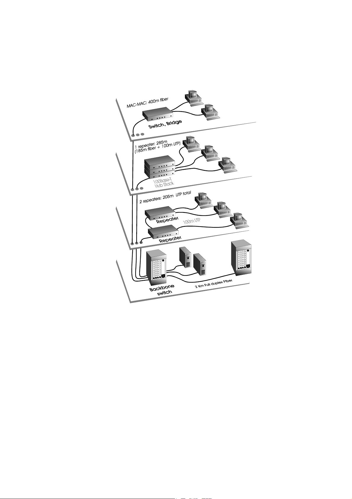
Cabling Requirement and Site Preparation
Due to the scaled-down MAC address slot time, 100Base-T (-TX,
-T4, -FX) has different topology rules than that of 10Base-T.
Figure Chapter
100Base-T.
The key cabling topology rules are:
• The maximum UTP cable length is 100 meters from an
end-station to a shared-access 100Base-TX hub.
2 -2 n Page 13 illustrates the topology rules of
• The maximum number of repeater counts (hops) is two in an
un-bridged all-UTP topology
• In a 2-repeater count, all-UTP topology, the maximum
cabling length is 205 meters for end-station / repeater /
repeater / end-station connections.
• In a single-repeater count UTP topology, a fiber cable
(100Base-FX) up to 205 meters can be used to connect
between a repeater and a backbone switch.
• A 400-meter half-duplex fiber cable is allowed for a MAC to
MAC connection (switch-to-switch).
The TE-100/S14 Switch fits into the 100Base-T cabling
architecture as an UTP end-station connecting to a 100Base-TX
cabling network. Therefore, the 100m UTP end-station
connection distance should be the only limitation in configuring
1
A single or a stacked 100Mbps hub is counted as one repeater. A
switch or a 10Base-T hub is not counted as a repeater, and is treated as
an end-station when applying the topology rules.
11
1
.
Page 12
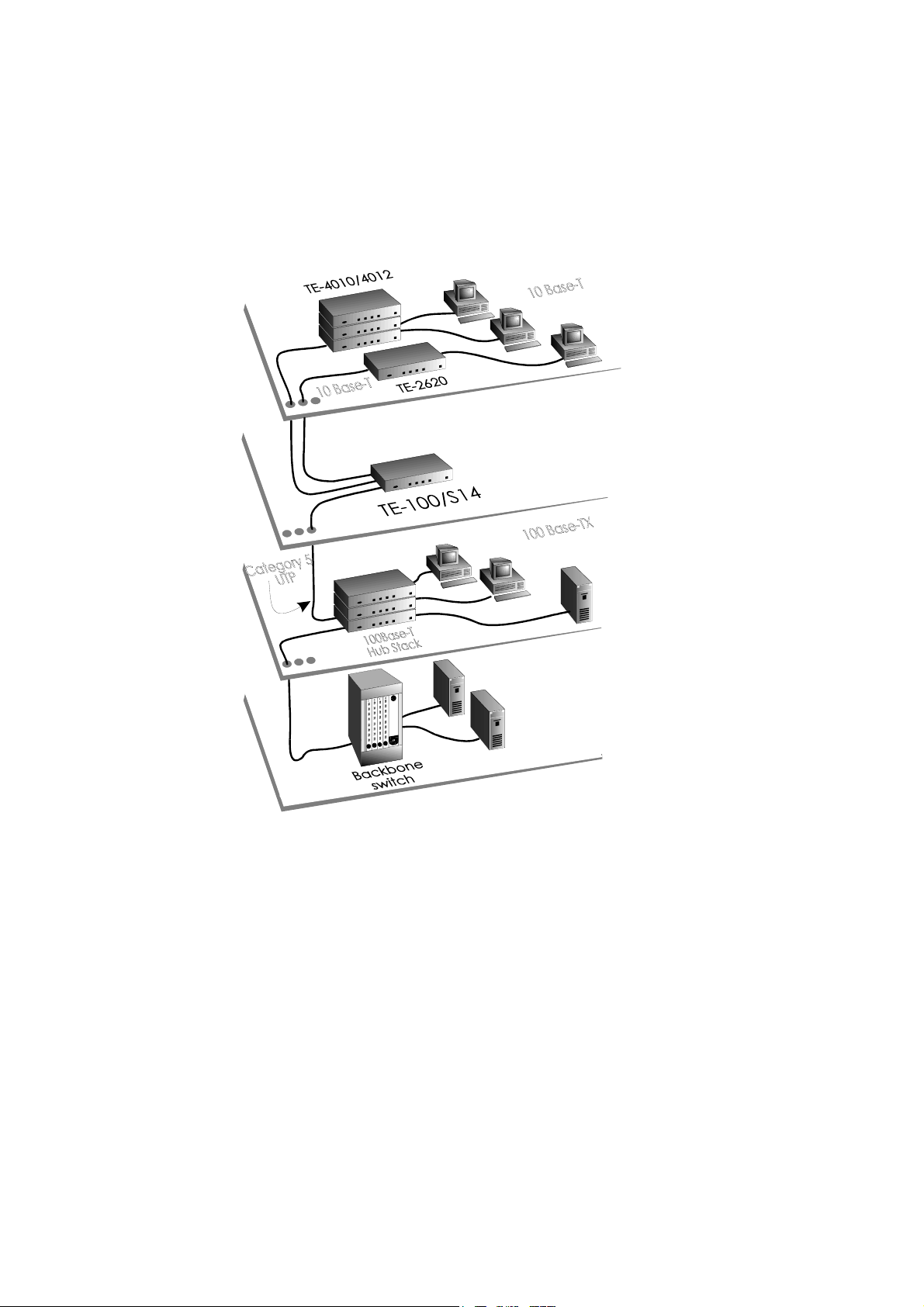
the TE-100/S14 Switch under the 100Base-T cabling architecture.
Figure Chapter
100/S14 Switch in a 100Base-TX cabling network.
As required by the 100Base-TX, the TE-100/S14 Switch expects a
2-pair, data grade (EIA 568, Category 5) UTP or STP cabling
system connecting to its 100 Mbps port.
2 -1 shows the possible placements of the TE-
Figure Chapter 2 -1, Examples of the TE-100/S14 wiring
environment
12
Page 13
Careful planning and site preparation is the key to success for
installing Fast Ethernet switches. Users should perform a
network bandwidth analysis based on their workgroup network
traffic needs, and to examine their workstation equipment for
other performance bottlenecks.
Figure Chapter 2 -2, 100Base-T cabling rules
13
Page 14
Unpacking and Setup
Now you have a good understanding of the cabling rules, your
own cabling environment, and the expected network load on your
workgroups. You are ready to integrate your TE-100/S14 Switch
with your network.
The following sections delineate the steps to setup, connect and
integrate your newly acquired TE-100/S14 Switch into your
network.
UNPACKING
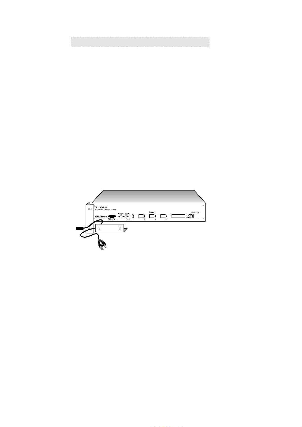
The TE-100/S14 Switch shipping carton (refer to Figure Chapter
2 -3
• 1 TE-100/S14 unit
• 1 AC power cord
• 2 Mounting brackets
• This user guide
If any item is found missing or damaged, please contact your local
TRENDnet reseller for replacement.
) should contain the following items:
Figure Chapter 2 -3, Unpacking a TE-100/S14
Switch
14
Page 15

O
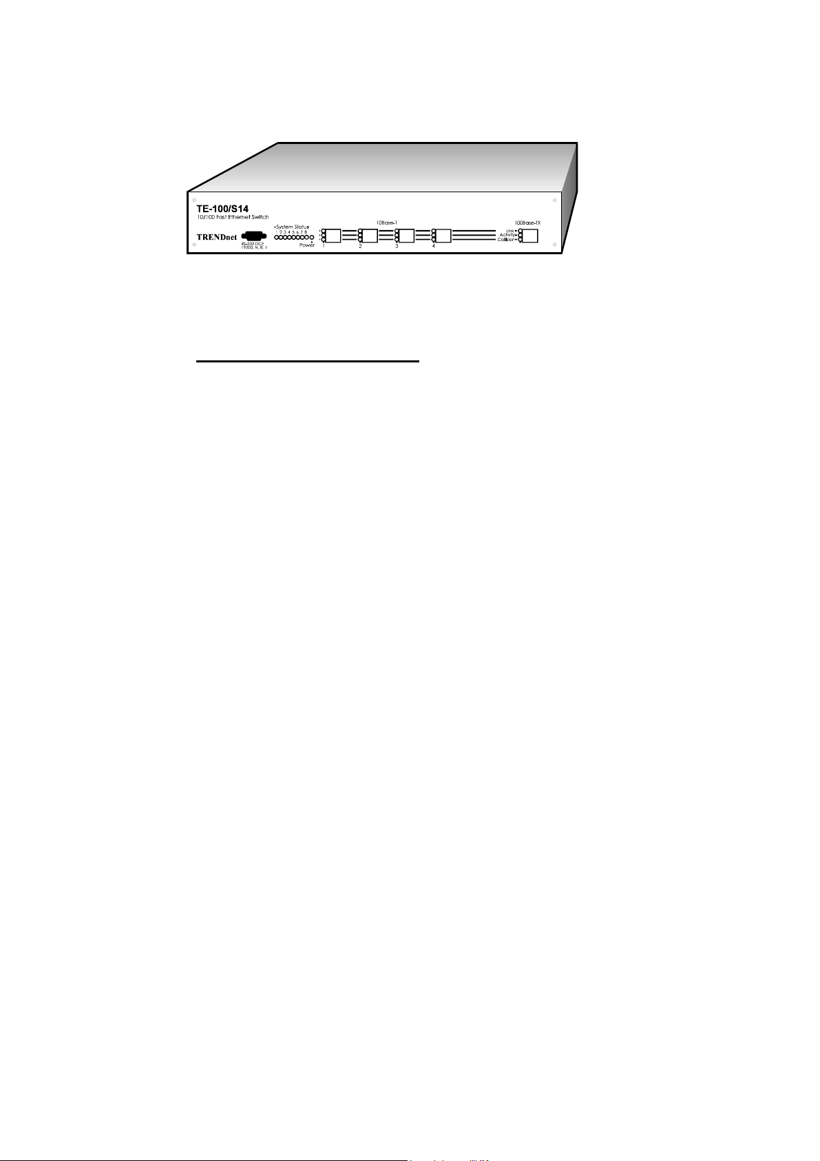
PERATIONAL FUNCTION DESCRIPTION
On the front panel, a TE-100/S14 Switch contains one 100Mbps
Fast Ethernet 100Base-TX RJ-45 port (A, Figure Chapter
four 10Mbps Ethernet 10Base-T RJ-45 ports (B), one RS-232
(DB9) Out-of-Band management port (C), eight System Status
LED lights (D), 3 port status LED lights for each 10 or 100 Mbps
port (E), and a power status LED light.
Figure Chapter 2 -4, Front panel view of a TE-
100/S14 Switch
2 -4),
POWER ON
The TE-100/S14 Switch can be used with AC power sources 90 250 VAC, 50 - 60 Hz. The Switch’s power supply will adjust to
the local power source automatically.
You may turn ON the power of the TE-100/S14 Switch without
having any or all the LAN segment cables connected. You should
observe the LED lights as the Switch is going through the PowerOn Self Test (POST) sequence. All System status LED lights
should go off, and Power LED light on, when the POST is
successful (refer to Figure Chapter
2 -6 on Page 17). The
15
Page 16

corresponding Link LED light will be turned on when a LAN
segment is connected to the port and functioning normally.
MOUNTING
The TE-100/S14 Switch can be either a desk-top or rack
mountable unit. For rack mounting, a pair of mounting brackets is
Figure Chapter 2 -5, Rack mounting a TE-
100/S14
included in the packing carton. Figure Chapter
shows the dimension and diagram for rack mounting.
2 -5
CONNECTING NETWORK CABLES
There are five RJ-45 ports on the TE-100/S14 Switch for
connection to five LAN segments; one for the 100Base-TX Fast
Ethernet segment, and four for the 10Base-T Ethernet segments.
Both segment types use the same RJ-45 connectors. Two-pair
Category 5, UTP cabling is required for the 100Base-TX segment.
For the 10Base-T segments, all existing cabling systems under the
10Base-T requirements will continue to suffice.
16
Page 17

If a cable is used for connecting a port to a workstation, just use
the standard UTP cable connectors with the RJ-45 pin layout.
If a cable is used for connecting to a hub, bridge, or another
switch, the Transmit (TD) and the Receive (RD) leads on one end
of the connectors must be swapped. Please refer to Appendix D
for pin layout details.
SETUP
The default setup of the TE-100/S14 Switch (shown in Appendix
B) should work in the majority of installations. If a different
setting is required for your specific networking environment,
please refer to the Out-of-Band Management section in Chapter 3,
“Configuring the Switch,” for changing these default settings.
CHECKING STATUS LED LIGHTS
When the power is first turned on, the TE-100/S14 Switch
performs a Power-On Self Test (POST). Please observe the status
LED lights to verify a proper installation (refer to Appendix A,
Page 35). These status LED lights also provide information about
the system unit and its connected Ethernet or Fast Ethernet LAN
segments during normal operation.
Figure Chapter 2 -6, The system status LED lights
17
Page 18

18
Page 19

Chapter 3 Configuring the Switch
Introduction
The TE-100/S14 Switch is designed to operate in workgroup
organizations without the need of, or unable to justify for
comprehensive network management software. It is also designed
to operate within the SNMP network management environment.
This chapter describes the details of configuring the TE-100/S14
Switch to support both environments.
Out-of-Band Management is the vehicle to access the TE-100/S14
Switch through a locally connected management terminal to the
RS-232 serial port. Through this port, a user can set up, monitor,
or change the configuration of the Switch.
The Spanning Tree Algorithm (STA) provides the capability for
the Switch to operate properly with other Bridges
network supporting the STA. Using the STA, the network will
prevent network loop, and automatically establish and activate a
backup path in the event of a path failure.
The TE-100/S14 Switch is set up to operate in either an unmanaged or managed network environment. In a simple network
hierarchy, the Spanning Tree Algorithm may be turned off.
1
Please refer to footnote 2, Page 25 for Bridge definition.
19
1
in a SNMP
Page 20

RS-232 Port Connection
The TE-100/S14 Switch uses a female 9-pin RS-232 serial
communication port for connection to a local management
terminal.
The RS-232 port is a DCE (Data Communication Equipment).
Figure Chapter
Terminal Equipment) such as a VT100 compatible terminal, or a
PC
with communication software emulating a VT100
terminal. Appendix C provides the pin reference to a 9-pin or 25pin DTE port. The switch-to-terminal (DCE/DTE) serial
communication speed is preset at 19,200 baud.
3 -1 shows the cable connection to a DTE (Data
Figure Chapter 3 -1, A locally connected management
terminal
Out-of-Band Management
The TE-100/S14 Switch can be configured using the Out-of-Band
Management facility. A management terminal connecting to the
RS-232 port on the Switch provides the access.
20
Page 21

Table Chapter 3 -1 shows the guidelines of setting up a VT100
compatible terminal, or the VT100 terminal emulation utility
under the Microsoft Windows as a management terminal for the
TE-100/S14 Switch. Users can select other terminal emulation
software contained in a number of communication software
packages.
Once the terminal or terminal emulation software is started, the
TE-100/S14 Switch will communicate with the terminal, and
display the following management functions (See Table Chapter
3 -2). In the following sections, there will be further discussion
on the interpretation and use of these management functions.
The TE-100/S14 Switch is factory set with an unique Ethernet
MAC Address. The Bold type-face in Table Chapter
indicates those parameters that are user changeable.
A user can also select Full / Half duplex support to maximize the
through-put of the LAN segments. If the Switch is set to Full
duplex, all ports will operate in Full duplex mode. No Full / Half
duplex selection is available at the individual port level. For
example, if a LAN segment is connected to a 10 Mbps shared
hub, the segment is operating at half duplex. Although the Switch
is set at Full duplex, the shared 10 Mbps LAN segment will not
have the full duplex bandwidth. If a LAN segment connects to a
TRENDnet TE-100/PCI, TE-PCI/T, TE-PCI/CT, or TE-PCI/CT+
network adapter card, or to another switch, the LAN segment will
have the full duplex bandwidth. This means that a dedicated
server or a high performance workstation connection to the TE100/S14 Switch will significantly benefit from this Full duplex
option.
3 -2
21
Page 22

The TE-100/S14 Switch is also capable of in-field upgrade of its
system firmware. A user can do so from a PC communication
software package which also includes the XMODEM feature.
The XMODEM will guide the user to down-load the firmware
code into the TE-100/S14 Switch. If a user needs to upgrade the
system firmware, please contact TRENDware technical support
for the latest firmware file and the detailed down-load procedures.
Terminal
Step
Communication
software
DCE/DTE line
setting
PC COM port
hardware setting
Assigning
control keys to
a non-VT100
system software
environment
VT100 Compatible
terminal
N/A
19,200 Baud, 8 N 1
(hardware setting)
N/A
N/A
PC VT100 terminal
emulation
VT100 emulation in Terminal /
Accessories in MS-Windows, or
other terminal emulation software
19,200 Baud, 8 N 1
(through the Terminal software)
Refer to PC COM port hardware
and Software setup guidelines
Deselect “Use function, arrow,
Ctrl keys for Windows” in
Terminal Preference..” in
Windows Terminal Accessories;
or refer to specific terminal
emulation software
Table Chapter 3 -1, Setting up the TE-100/S14 management terminal
22
Page 23

Control function
Switch Configuration 1. Switch Version No.
Port Configuration
(for each of the 100M,
and four 10M ports)
Spanning Tree
Configuration
Down-load new
system firmware
Re-load factory
default setting
Exit
System display User selection
2. Switch Name
3. MAC Address
4. Technical Support
5. Full / Half duplex
(all ports)
Save change
Exit
Ether State
Port Status
Port Priority
Save change
Exit
Enable / Disable
Bridge (switch) Priority
Root Cost
Hello Time
Forward Delay Time
Max Age Time
Root Bridge
Root Port
Y / N
Exit
Y / N
Exit
V1.10 (Fixed)
10/100 (changeable)
(Factory preset)
(Factory preset, changeable)
Enable / Disable (changeable)
F2 key
F4 key
Enable / Disable
Block, Learning, Listening,
Forwarding, Disable
1 (Hi) - 255 (Lo)
F2 key
F4 key
Enable / Disable
32768 (changeable)
(Reflected STA result)
10 sec. (range: 1 - 10 sec.)
30 sec. (range: 4 - 30 sec.)
40 sec. (range: 6 - 40 sec.)
(MAC addr. of the current
Root Bridge)
(Reflected STA result)
Space Key (toggle)
F4 key
Space Key (toggle)
F4 key
* Note: Bold typeface fields
are user changeable.
Table Chapter 3 -2, The TE-100/S14 Out-of-Band management functions
23
Page 24

Port Management
The ports on the TE-100/S14 Switch can be managed through the
Out-of-Band RS-232 port. In Table Chapter
Configuration allows a user to enable or disable a port
connecting to a LAN segment.
The Port Configuration also allows a user to set the priority of a
port. A number (ranging 1 - 255, high - low) can be entered to
identify the priority setting of the Switch. This number, in
conjunction with the pre-set port ID, is used under the Spanning
Tree Algorithm to determine the “Root Port” for forwarding
Ethernet data, and to avoid network loop.
The Port Status displays the state of the port at any given time.
A port will display one of the states (Blocking, Learning,
Listening, Forwarding, and Disable) responding to the port
Enable / Disable setting, and to the dynamic changes in routing
paths of the surrounding network.
3 -2, page 23, Port
24
Page 25

Spanning Tree Algorithm
The TE-100/S14 Switch implements the Spanning Tree Algorithm
(henceforth STA) to provide the following functions:
• Network loop detection and prevention - There can be
only one path between any two bridged Ethernet LAN
segments
packets may loop indefinitely. STA detects any looped path
and selects the path with the lowest “path cost” as the active
path, while blocking the other paths.
• Automatic topology re-configuration - If an active path
fails and there is a backup path, the backup path will be
automatically activated, and the STA will automatically reconfigure the network topology.
The detailed Algorithm is defined in the STA Specification. The
following introduces the key information and terminology needed
to interpret the parameters used in the TE-100/S14 Switch that
support the STA. It is also helpful to understand the effects of
changing these parameters. Appendix B lists the defaults setting
used by the TE-100/S14 Switch.
STA operates at two levels, the Bridge
In addition, STA uses several timers to periodically ensure the
integrity of the Bridges and their ports in a network.
1
. If there are more than one path, forwarded
2
level and the Port level.
1
A shared hub is a star topology cabling implementation of the same
LAN segment, therefore, is not a Bridge.
2
Bridge is the standard terminology used in the Spanning Tree
Algorithm Specification, which could be a bridge or switch.
25
Page 26

1. At the Bridge level:
Root Bridge: A network must first establish a reference Bridge,
from which all data forwarding path values are calculated,
compared, and determined. The Root Bridge has the lowest
Bridge Identifier
1
(Bridge Priority + MAC address).
Bridge Priority: This is a user changeable parameter. The
smaller the number is set, the higher the Bridge Priority is. This
parameter enables all Bridges in a network to establish a Root
Bridge. A change to the Bridge Priority may cause all the Bridges
in the network to re-establish a new Root Bridge. A high Bridge
Priority increases the chance for the Bridge being selected as the
Root Bridge.
Root Path Cost: From each Bridge, Root Path Cost is the total
Path Cost of reaching the Root Bridge from a Designated Bridge.
A Root Bridge has Root Path Cost of 0.
Designated Bridge: From each LAN segment, the attached
Bridge that has the lowest Root Path Cost to the Root Bridge is
the Designated Bridge. It forwards data packets for that LAN
segment. In case all attached Bridges on a segment have the same
Root Path Cost, the Bridge with the lowest Bridge Identifier
becomes the Designated Bridge.
2. At Port level:
Designated Port: This is the port on each Designated Bridge that
forwards data packets for the attached LAN segment.
Root Port: Each Bridge has a Root Port that has the lowest Path
Cost to the Root Bridge. In case there are several such ports of
the same Path Cost, the one with the lowest Port Identifier (Port
Priority + pre-assigned Port ID) becomes the Root Port
1
A Bridge’s MAC address is only used to decide the Root Bridge when
there are 2 or more Bridges with the same Bridge Priority.
2
In a Bridge, a port is Blocked, if it is not a Root or a Designated Port.
26
2
.
Page 27

Port Priority: This is a user changeable parameter for each port
on a Bridge. In conjunction with a pre-set port ID, this parameter
is used by the Bridge to determine the Root Port of a Bridge.
Path Cost: This parameter is fixed
1
, therefore not displayed by
the TE-100/S14 Switch, in order to ensure that the Fast Ethernet
LAN segment will always be used. The 100Mbps segment has an
assigned Path Cost of 10, and each 10Mbps segment has assigned
Path Cost of 100, based on the STA Specification.
3. Timers:
Max. Age Time: This is a user changeable parameter. Should a
Bridge fail to receive an identifier packet from the current Root
Bridge within this time, it assumes that the current Root Bridge
has failed. An attempt will be initiated to establish a new Root
Bridge for the network.
Hello Time: This is a user changeable parameter. Should a
Bridge take over as the Root Bridge, the Hello Time setting will
be used as the interval timer to send out identifier packets to other
Bridges for notifying its existence as the Root Bridge. The Hello
Time cannot be set longer than the Max. Age Time as
configuration errors will occur.
Forward Delay: This is a user changeable parameter. This is the
delay time that each port on a Bridge waits in the Listening state
before changing from the Blocking state to the Forwarding state.
1
This is changeable parameter, based on the STA specification.
However, it is fixed by the TE-100/S14 Switch implementation.
27
Page 28

4. Example:
Figure Chapter
Bridges prior to applying the STA. In this simplified example,
Bridge 1 has three ports with Port 1 connecting to a 100Base-TX
segment (LAN 1), and Port 2 connecting to a 10Base-T segment
(LAN 2). Port 3 is not connected to any LAN segment. One may
consider Bridge 1 as the TE-100/S14 Switch, with one port
connecting to a Fast Ethernet LAN segment, and only one of the
four ports connecting to a Ethernet segment. Both Bridge 2 and 3
connect to another Ethernet segment (LAN 3). In this example,
there will be a network loop problem.
Figure Chapter
3 became the Root Bridge as it has the lowest Bridge ID, it is also
the Designated Bridge for both LAN 1 and 3. Bridge 1 became
the Designated Bridge for LAN 2. Port 1 of Bridge 1, and Port 2
of Bridge 2 became the Root Ports as they have the lowest Root
Path Costs to Bridge 3. Port 1 of Bridge 2, after applying the
STA, became neither a Root Port or a Designated Port, therefore
will not forward data packets. As the result, this port is Blocked.
3 -2 gives an example of the parameters of three
3 -3 shows that, after applying the STA, Bridge
28
Page 29

LAN 1 - 100Mbps, Path Cost = 10
Port 1
Bridge 1
Port 2 Port 3
10Mbps, Path Cost = 100
Bridge ID = 21
LAN 2
Port 1
Bridge 2
Port 2
Bridge ID = 30
LAN 3 - 10Mbps, Path Cost = 100
Figure Chapter 3 -2, STA parameters at
LAN 1 - 100Mbps, Path Cost = 10
Root Port, Root Path Cost = 10
Port 1
LAN 2
Bridge 1
Port 2 Port 3
Designated Port
10Mbps, Path Cost = 100
Blocked
Port 1
Bridge 2
Port 2
Designated Bridge
Set-Up
Port 1
Bridge 3
Port 2
Designated Port
Port 1
Bridge 3
Port 2
Designated Port
Bridge ID = 15
Root Bridge
Root Path Cost=0
Root Port, Root Path Cost =100
LAN 3 - 10Mbps, Path Cost = 100
Figure Chapter 3 -3, STA parameters after applying the STA
29
Page 30

30
Page 31

Chapter 4 Network Management
Operating within the SNMP environment
The TE-100/S14 Switch operates easily with other Bridges1
within a network managed by the SNMP network management
protocol, although, it does not appear as a manageable SNMP
agent from a SNMP management terminal. Make sure that the
STA is enabled to avoid network looping or possible blocking of
forwarding paths.
The Out-of-Band Management facility enables a user to examine
the status of the Switch and the LAN ports as the Switch interacts
with other Bridges in the network.
STA is a complex subject. Therefore, it is best to keep the default
settings as set in the factory. The factory default setting should
cover the majority of installations. Table Chapter
the user changeable parameters in the TE-100/S14 Switch, and the
effect of changing them. Appendix B shows the default settings
and ranges of these parameters.
4 -1 shows
Operating without the SNMP environment
In a simple network installation where there is a network
hierarchy without any possibility of network looping, you may
turn off the STA in the TE-100/S14 Switch at the Bridge level
1
Please see footnote at page 25 for the Bridge definition.
2
Please see “Bridge level” at page 25.
31
2
.
Page 32

If the possibility of network loop exists, just leave the STA
enabled along with other Bridges in the network. The TE100/S14 Switch will interact with other Bridges to dynamically
establish forwarding paths in the network.
Bridge level
STA
parameters
Enable /
Disable
Bridge Priority
Hello Time
Max. Age Time
Forward Delay
Port level STA parameters
Enable /
Disable
Port Priority
Settings Effects Comment
Enable /
Disable
lower the
number,
higher prio.
1 - 10 sec. No effect, if not
6 - 40 sec. Contend for Root
4 - 30 sec. High number
Enable /
Disable
lower the
number,
higher prio.
Participate in or
remove from STA
path establishment
Increase chance
becoming the Root
Bridge
Root Bridge
Bridge, if not
receive a BPDU in
this period
delays the change
in state
Enable or disable
this LAN segment
Increase chance to
become Root Port
Enable in a SNMP
network
Avoid, if the switch is
used in workgroup level
of a large network
Never set greater than
Max. Age Time
Avoid low number for
un-necessary reset of
Root Bridge
Max. Age ≤ 2 x
(Forward Delay -
1)
Max. Age ≥ 2 x (Hello
Time +
1)
Disable a port for
security or problem
isolation
Table Chapter 4 -1, Effects of changing the user changeable STA
parameters
32
Page 33

Chapter 5 Diagnostics
Power-On Self Test
A Power-On Self Test (POST) sequence takes place when the TE100/S14 Switch is first turned on (cold boot). Software reset
(warm boot) through the RS-232 port is not supported to prevent
unauthorized remote re-boot.
The POST sequence checks the system integrity by performing
the following component tests:
− System boot
− RAM test
− Timer and interrupt controller tests
− Cache controller test
− RS-232 diagnostic port test
− BIOS test
− EEPROM checksum test
− Program load checksum test
− Ethernet ports test
Besides the Power On/Off LED, there are eight System LED
lights used to display the results of these tests during the POST
sequence. The LED status lights further display test results in two
categories, the System component test status, and the LAN port
test status. Any error that arises from the System component tests
means that the Switch failed to function. Any LAN port error(s)
indicates that, although the displayed LAN port(s) is not
functioning, the TE-100/S14 Switch is operational with the
remaining LAN ports.
The following two sections describe the meaning of the LED
status lights (See Appendix A, Page 35).
33
Page 34

System Status
If the System passes the POST sequence and all LAN ports are
operational, all LEDs - will be off (See Figure Chapter
2 -
6 on Page 17).
If there is a System error, the LED light will be On, and the
LEDs - will display the System error code.
Some of the System errors and LAN port errors can be resolved
by restarting the System, or with remote technical support from
TRENDware (See shaded areas in Appendix A, Page 35,
100/S14 system POST status LED lights). The remaining System
errors require that the unit be returned to your nearest TRENDnet
reseller for repair.
The TE-
LAN segment LED Status
In addition to the System Status LED lights, there are three LED
lights (See Page 36) for each port displaying the operating status
of the connected 10Mbps or 100Mbps LAN segment.
Each Link LED light displays the status of corresponding LAN
segment during Power-On.
During active switching of LAN data traffic, Link LED lights
display the change in the state of the segment, Activity LED
lights display the transmitting and receiving of data on the
corresponding LAN segments. The Collision LED lights reflect
the efficiency of carrying meaningful data traffic. Users should
re-arrange workgroups sharing a LAN segment when the
Collision LED stays on consistently for this segment. For
example, on a segment with dedicated end-station connection, the
Collision LED should stay off all the time.
34
Page 35

Appendices
Appendix A Status LED Indicators
SYSTEM & LAN PORT STATUS
System error LED
Off -
On -
LAN port error LED
Error
Status
No error
Boot
RAM
Interrupt
controller
Timer
controller
Cache
controller
RS-232 port
BIOS
EEPROM
Program
down-load
Normal
Record LED error code and
contact TRENDware for
support
Record LED error code and
return the unit.
Record LED error code and
return the unit.
Record LED error code and
return the unit.
Record LED error code and
return the unit.
Record LED error code and
return the unit.
Record LED error code and
contact TRENDware for
support
Record LED error code and
contact TRENDware for
support
Record LED error code and
contact TRENDware for
support
Action
Note: LED
is
reserved.
port
positions:
1234↑
(100Mbps)
Port 1 - 5
error (s)
The system board is OK, the
reported LED port(s)
disabled. Record LED status
and contact TRENDware for
support.
The TE-100/S14 system POST status LED lights
35
Page 36

LAN S
EGMENT STATUS
Port
LED
Link
Activity
Collision
Status LAN segment state Action
On
Off
Off
Blinking
On
Off
Blinking
On
LAN segment Normal
No packet traffic
TD or RD packets on
this LAN segment
Heavy packet traffic
No collision -
Collision on this LAN
segment -
Jabber, serious problem
-
Check connections
on this cable segment
Check if consistently
heavy
Normal
Normal
Check this LAN
segment
LAN segment status LED lights
36
Page 37

Appendix B Switch Default setting
Parameter Default Range Data type
Device Name
Location
Bridge State
Bridge Priority
Hello Time
Max. Time
Forward Delay
Aging Time
MAC Address 0080C8xxx
Port State
(for each port)
Port(s) Priority
Path Cost
(100Mbps)
Path Cost (10Mbps) 100
Note: Bold type face indicates changeable parameters.
10/100
Enable
32768
10 sec.
40 sec.
5 sec.
300 sec.
Enable
128
10
0 - 65535 Integer
1 - 10 sec. Integer
6 - 40 sec. Integer
5 - 30 sec. Integer
0 - 10 ∧ 6
0 - 255 Integer
String (32
bytes)
String (32
bytes)
Integer
Integer
Integer
The TE-100/S14 default parameter settings for the Spanning Tree
Algorithm
37
Page 38

Appendix C RS-232 Pin Specification
The RS-232 serial port of a TE-100/S14 Switch uses a 9-pin
female connector. The port can be connected to a VT100 type of
terminal, or a PC, or a workstation emulating a VT100 terminal.
For a local connection, the table below shows the pin layout of a
9-pin to 9-pin, or a 9-pin to 25-pin cable connection between the
TE-100/S14 Switch and the management terminal.
TE-100/S14 (DCE) Terminal (DTE)
Pin
Signal name for 9-pin for 25-pin Signal
number
1 not used 1 - not used
2 transmit (TD) 2 3 RD
3 Receive (RD) 3 2 TD
4 Data Carrier Detect
(DCD)
5 signal ground (SG) 5 7 SG
6 Data Terminal Ready
(DTR)
7 clear to send (CTS) 7 4 RTS
8 request to send (RTS) 8 5 CTS
9 not used 9 - not used
The TE-100/S14 Switch to Terminal RS-232 pin connections
4 20 DTR
6 8 DCD
name
38
Page 39

Appendix D RJ-45 Pin Specification
When connecting the TE-100/S14 Switch to another switch, a
bridge or a hub, a modified cross-over cable is necessary. Please
review these products for matching cable pin assignments.
The following diagram and tables show the standard RJ-45
receptacle/connector and their pin assignments for the switch-tonetwork adapter card connection, and the cross-over cable for the
switch-to-switch/hub/bridge connection.
The standard RJ-45 receptacle/connector
39
Page 40

Contact Media Direct Interface Signal
1 TD + (transmission)
2 TD - (transmission)
3 RD + (reception)
4 not used
5 not used
6 RD - (reception)
7 not used
8 not used
The Standard Category 3 cable, RJ-45 pin assignment
1 TD +
2 TD -
3 RD +
6 RD -
4 TD +
5 TD -
7 RD +
8 RD -
1 TD +
2 TD -
3 RD +
4 TD +
5 TD -
7 RD +
6 RD -
8 RD -
The pin assignment for Category 5, 4-pair cross-over cable
40
Page 41

Appendix E Specifications
PORT CONFIGURATION
1 x 100Mbps LAN port -
• Complies to IEEE 802.3, ISO 8802-3 10Base-T Ethernet
• IEEE 802.3 Frame types: Transparent
• Switched IEEE 802.3 MAC layer frame size: 64 - 1518
• RJ-45 port connector with built-in transceiver
• Max. data rate: 100 Megabits/sec. (full duplex)
• Topology: Star
• Protocol: CSMA/CD
• VLSI LAN controller chip
4 x 10Mbps LAN ports -
• Complies to IEEE 802.3, ISO 8802-3 10Base-T Ethernet
standard
• IEEE 802.3 Frame types: Transparent
• IEEE 802.3 MAC layer frame size: 64 - 1518
• RJ-45 port connector with built-in transceiver
• Data rate: 10 Megabits/sec. (Full duplex)
• Topology: Star
• Protocol: CSMA/CD
• VLSI LAN controller chips
41
Page 42

H
ARDWARE
• Bus master LAN controller with custom design board
• Field upgradeable 128 KB non-volatile EEPROM for
configuration, program code
• 1 x DB9 RS-232D DCE port; async. 8-bit data, 1 stop bit, no
parity, 19.2K baud
LAN cabling support -
• For 10Base-T ports: Two-pair Category 3,4,5 UTP cabling
• For 100Base-TX port: Two-pair Category 5 UTP or STP
cabling
Physical aspects -
Operating temperature: 5 - 50 degrees Celsius
Humidity: 5 - 95% non-condensing
Input power: 90 - 250 VAC, 50 - 60 Hz auto-select
Power consumption: 20 watts maximum
Ventilation: 2 built-in DC fans
Dimension: 17.36 in (w), 2.85 in (h), 9.37 in (d)
Weight: 8 lbs
42
Page 43

Index
100Base-T See Fast Ethernet
Activity LED 34
Bridge 25
Bridge Priority 26
Cabling Requirement 11
Category 3 cable, RJ-45 pin assignment 40
Category 5, 4-pair cross-over cable 40
changeable STA parameters 32
Collision LED 34
Connecting network cables 16
DCE 20, 38
TE-100/S14 default parameter settings 37
TE-100/S14 wiring environment 12
Designated Bridge 26
Designated Port 26
DTE 20, 38
Fast Ethernet 7
Forward Delay 27
front panel 15
Full / Half duplex support 21
Hello Time 27
IEEE 802.1D See Spanning Tree Algorithm
LAN segment LED Status 34
LAN segment status LED lights 36
Link LED 34
management terminal 20
Max. Age Time 27
Mounting 16
Out-of-Band Management 20, 23
43
Page 44

Path Cost 27
Port Configuration 24
Port Management 24
Port Priority 27
Port Status 24
POST See Power-On Self Test
Power-On Self Test 17, 33
RJ-45 Pin Specification 39
RJ-45 receptacle/connector 39
Root Bridge 26
Root Path Cost 26
Root Port 26
RS-232 See Management terminal
RS-232 pin connections 38
RS-232 Port Connection 20
Setup 17
SNMP 31
Spanning Tree Algorithm 25, 37
STA See Spanning Tree Algorithm
Status LED lights 17
Switched Ethernet 8
system POST status LED lights 35
System Status 34
Timers 27
VT100 20
XMODEM 22
44
Page 45

 Loading...