

Page 1

Operation Manual
™
Smart-UPS
Uninterr upti b le P ow er Sup ply
Tower
750/1000/1500/2200/3000 VA
100/120/230 Vac
500 VA
100 Vac
Page 2

Page 3
Overview
Product Description
The APC™ by Schneider Electric Smart-UPS™ is a high performance uninterruptible power supply (UPS ). The UPS
provides protection for electronic equipment from utility power blackouts, brownouts, sags, and surges, small utility
power fluctua tions and large disturbances. The UPS also provides battery ba ckup power for c onnected equipment until
utility power re turns to safe levels or the bat teries are fully disc harged.
This user manual is available on the enclosed CD and on the APC by Schneider Ele ctric Web site, www.apc. com .
Important Safety Messages
Read the instructions carefully to become familiar with the equipme nt before trying to install, operate, service or
maintain it. The following specia l messages may appear throughout this manual or on the equipment to warn of
potential hazards or to call attention to inform ation that clarifi es or si mp lifies a procedure.
The addit ion of this symbol to a Caution prod uct safety label indica tes that a hazard exis ts that can result in
injury and product damage if the instructions are not followed.
The following safety me ssages may appear throughout this manual to warn of poten tial hazards.
CAUTION
CAUTION indicates a potentially hazardous situation which, if not avoided, can result in equipment damage and minor or moderate injury.
CAUTION
CAUTION indicates a potentially hazardous situati on which, if not avoided, can result in equipment damage.
Safety and General Information
Inspect the package conte nts upon receipt. Notify the carrier and dealer if there is any
damage.
Read the Safety Guide supplied with this unit before installing the UPS.
• Adhere to all national an d local electrical codes.
• This UPS is intended for indoor use only.
• Do not operate this UPS in direct sunlight, in contact with fluids, or where there is excessive dust or humidity.
• Be sure the air vents on the UPS are not blocke d. Allow adequate space for proper ventilation.
• The battery typically lasts for two to five years. E nvironmental factors impact battery life. Elevated ambient
temperatures, poor quality utility power, and frequent short duration discharges will shorten battery life.
• Connect the UPS power cable directly to a wall outlet. Do not use surge protectors or extension cords.
• The equipment is heavy. Always prac tice safe lifting techniques adequat e for the weight of the equipment.
• The model and serial numbers are located on a small, rear panel label. For some models, an additional label is
located on the chassis under the front bezel.
• Alway s recy cl e u s ed ba t te ries.
• Recycle th e package materials or save them for reu se.
1Smart-UPS 750/1000/ 1500/2200/3000 VA 100/120/230 Vac / 500 VA 100 Vac Tower
Page 4

Specifications
For additional specifications, refer to the APC by Schneider Electric Web site at www.apc.com.
Environmental
Operating 0° to 40° C (32° to 104° F)
Temperature
Storage
-15° to 45° C (5° to 113° F)
charge UPS battery ev ery six months
Maximum
Elevation
Humidity 0% to 95% relative humidity, non-condensing
Operating 3,000 m (10,000 ft)
Storage 15,000 m (50,000 ft)
Smart-UPS 750/1000/1500/2200/3000 VA 100/120/230 Vac / 500 VA 100 Vac Tower2
Page 5
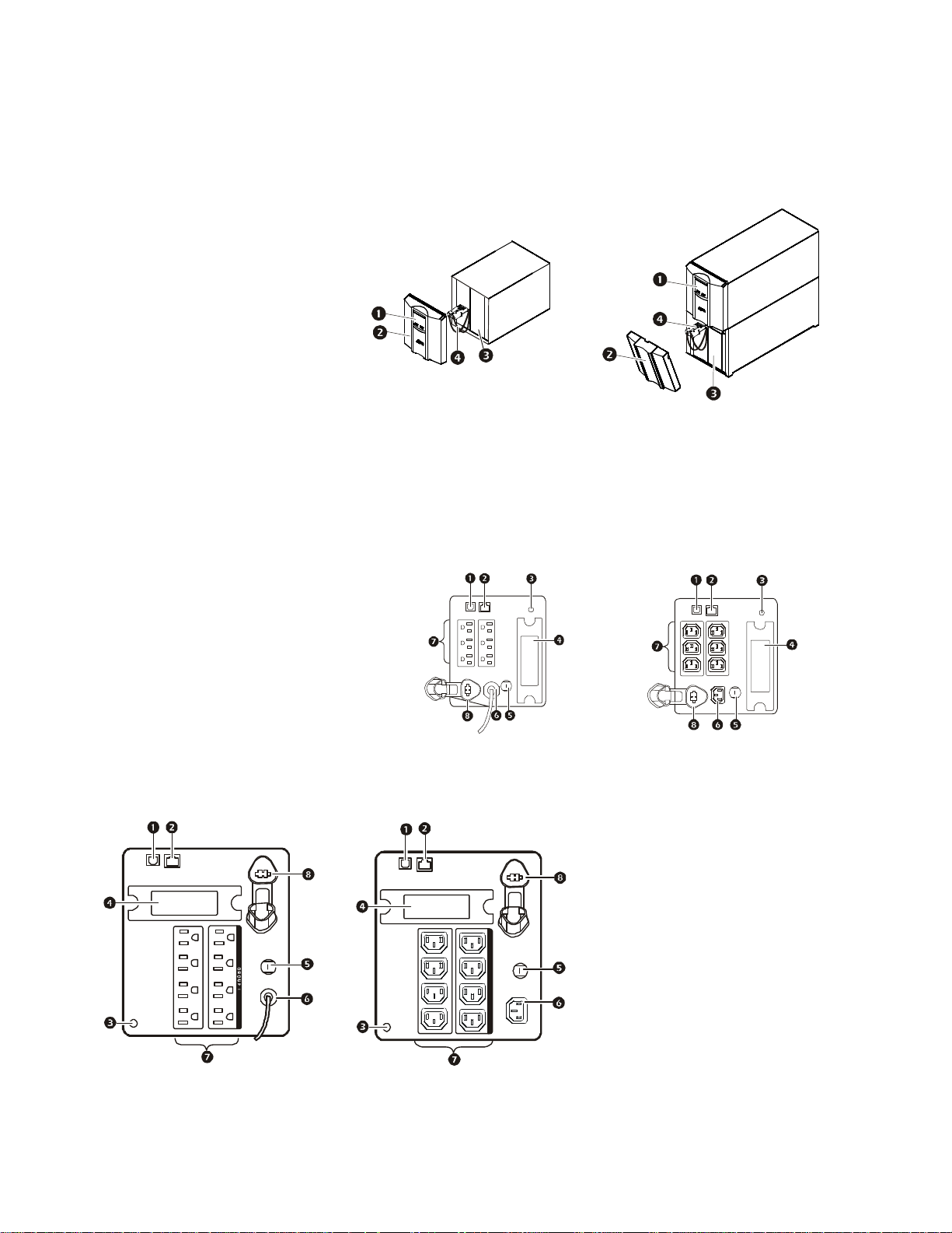
Product Overview
su
Front panel features
Display interface
1
Bezel
2
Battery
3
Internal ba ttery connector
4
500/750/1000/1500 VA 2200/3000 VA
Rear panel features 500 VA to 1500 VA models
1 USB port
2
Serial port
3 Chassis ground screw
4 SmartSlot
5 Circuit breaker
6 UPS input
7 Outlets
8 Internal or external battery connector
500/750 VA 100 Vac
750 VA 120 Vac
su0326b
su0453a
su0452a
750 VA 230 V ac
0327b
1000/1500 VA 100 Vac
1000/1500 VA 120 Vac
GROUP 1
su0325c
1000/1500 VA 230 Vac
GROUP 1
su0328c
3Smart-UPS 750/1000/ 1500/2200/3000 VA 100/120/230 Vac / 500 VA 100 Vac Tower
Page 6
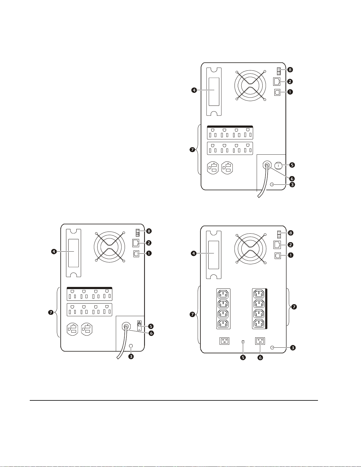
Rear panel features 2200 VA and 3000 VA models
su0351b
su0330a
su0329b
1 USB Port
2 Serial port
3 Chassis ground screw
4 SmartSlot
5 Circuit bre aker
6 UPS input
7 Outlets
8 EPO connector
2200 VA 120 Vac
G R O U P 1
2200/3000 VA 100 Vac
3000 VA 120 Vac
G R O U P 1
2200/3000 VA 230 Vac
GROUP 1
Installation
For UPS installation information, refer to the Sma r t-UP S Instal lation Guide 750/1000/1500/2200/3000 VA 100/120/
230 Vac, 500 VA 100 Vac Tower, that is included with the UPS. The Installatio n guide is also ava ilable on the
Documentation CD included with the UPS and on the APC by Schneider Electric Web site, www .apc.com.
Smart-UPS 750/1000/1500/2200/3000 VA 100/120/230 Vac / 500 VA 100 Vac Tower4
Page 7

Operation
Connect Equ ipment
CAUTION
RISK OF EQUIPMENT DAMAGE
• Adhere to all local and nat ional electrical codes.
• Wiring should be performed by qualified ele ctrician.
• Always connect the UPS to a grounded outlet.
Failure to follow the s e instructions can result in equipment damage
Note: The 2200/3000 VA 100 Vac model UPS will charge to 90% capacity in the first four and a half
hours of normal operation.
All other models will ch arge to 90% capacity in the first three hours of normal operation
Do not expect full battery runtime capability during this initial charge period.
1. Connect equipment to the outlets on the rear panel of the UPS.
2. Connect the UPS to the building utility power.
Always connect the UPS to a two pole, three wire, grounded source.
3. To use the UPS as a master O
4. Press the O
See “Main Outlet Group and Controlled Outlet Group” on page 10 for information on how to configure the outlet
groups.
N/OFF button on the front panel of the UPS to turn on the UPS and all connected equipment.
N/OFF switch, turn on all the e quipmen t that is connected to the UPS.
Rear Panel Features
Serial port: Connect to a computer to use power management software.
USB port: Connect to a computer to use power management software.
Note: S erial and USB communication can not be use d simultaneously.
Ground Screw: The UPS features a ground screw for connec ting the ground leads
on transient voltage devices. Prior to connecting a ground le ad, disconnect the UPS
from utility powe r.
su0441a
5Smart-UPS 750/1000/ 1500/2200/3000 VA 100/120/230 Vac / 500 VA 100 Vac Tower
Page 8

Display Panel
su0343a
A
Electric
Online LED
1
UPS
2
3
4
5
6
7
8
9
Using the display interface
Use the UP/DOWN arrow buttons to scroll through the main menu options. Press ENTER to view the
submenus under each main menu option. Press
Standard menus
ON/OFF key
On Battery LED
Site Wiring Fault LED
Replace Battery LED
Display interface
UP/DOWN arrow keys
ENTER key
ESCAPE key
PC by Schneider
ESCAPE to exit a submenu a n d return to a m ain m enu.
The Standard menus are the most commonly use d menus.
Menu General Functions
View UPS inform ation:
• Operating Mode
Status
Configuration
Te st & Diags
About
• Efficiency
• Load Power
• Load V A
• Battery Charge state
• Estimated Runtime
Configure UPS settings:
• Language
• Local Power Quality: Good, Fair, Poor
• Menu Type: Standard or Advanced
•Audible Alarm
Perform UPS tests and diagnostic functions:
• UPS Self Test
• UPS Alarms Test
• Calibration Test
View UPS inform ation:
• UPS Model
• UPS Part No.
• UPS Serial No.
• UPS Manufacture Date
•Battery Temp
• Input
• Output
• Last Transfer
• Last UPS Self Test
• Displ ay (Auto Dim, Auto Off, Always On)
• Battery Instal l D a te
• Reset to Factory Default
• Battery Part No .
• Battery Instal l D a te
• Replace Battery by
• UPS Firmware 1
Smart-UPS 750/1000/1500/2200/3000 VA 100/120/230 Vac / 500 VA 100 Vac Tower6
Page 9

Advanced menus
The Advanced menus provide additional options for the UPS and are availabl e only if the display interface is
configured to use the Adva nced menus.
Menu Gene r a l Functions
View detailed UPS information:
•Battery Temp
• Input
•Output
• Last Transfer
• Last UPS Self Test
• Outlet Group 1 (if
• NMC IP Address (if NMC is available)
• Battery Instal l D a te
• Reset Energy Meter
• Enter Setup Wi zard
• Firmware Update (standby mode)
• Reset to Factory Default
• Config Main Group Outlets
• Config Group 1 Outlets (if
available)
• Config NMC (if NMC is available)
Controlled Outlet is available)
Controlled Outlet is
Status
Configuration
• Operating Mode
• Efficiency
• Load Power
• Load VA
• Load Amps
• Load Energy
• Battery Charge state
• Estimated Runtime
• Battery Voltage
Configure advanced UPS settings:
• Language
• Lo cal Power Quality
• Men u Type
•Audible Alarm
• Display (Auto Dim, Auto Off, Always On)
• Sensitivity
• Low Transfer
• High Transfer
• Low Battery Warning
• Auto Self Test
Control
Te st & Diags
Log
About
Control the Main and Switched Outlet Group to turn on, turn off, shutdown, or reboot.
Perform UPS test and diagnos tic functions:
• UPS Self Test
• UPS Alarms Test
• Calibr ation Test
View the event and error logs for information about UPS events and faults that have occurred.
View UPS inform ation:
• UPS Model
• UPS Part No.
• UPS Serial No.
• UPS Manufacture Date
• Battery Pa rt No .
• Battery In stall Date
• Replace Battery b y
• UPS Firmware 1
• UPS Firmware 2
• UPS Firmware 3
• UPS Firmware 4
• NMC M odel No.*
• NMC Serial No.*
• NMC Hardware Version*
•NMC Manufacture Date*
•NMC MAC Address*
• SmartSlot FW 1*
• SmartSlot FW 2*
• SmartSlot FW 3*
*If NMC is available
7Smart-UPS 750/1000/ 1500/2200/3000 VA 100/120/230 Vac / 500 VA 100 Vac Tower
Page 10

Configuration
UPS Settings
Start up Settings
Configure thes e settings at initial start up, using the display interface. As an alternative, configuration can be
performed using PowerChute
™
software.
Note: During start up, us e the display interface to configure these settings. If nothing is selecte d, the
unit will use the default settings.
Function Factory Default Options Description
Language English
Local Power
Quality
Good
•English
• French*
•German*
• Spanish*
• Italian*
• Portuguese*
• Japanese*
• Good
•Fair
•Poor
The language for the display interface.
*Language options will vary by model.
Select the quali ty of input utility power.
• If Good is selected, the unit will go on battery power
more oft en to provide the cleanest power supply to the
connected equipment.
• If Poor is selected, the UPS will tolerate more
fluctuati ons in p ower an d wi ll g o on ba tter y p ower less
often.
If uns ure of the local po w e r qu ality, select Goo d .
The Standard menus dis play a limited s et of menus
and options. The advance d me nus include all
parameters.
Menu Type Standard
Standard or
Advanced
General Settings
Configure these settings at any time. Use the display interfac e or PowerChute software.
Function Factory Default Options Descriptio n
High Transfer Point
100 Vac:
108 Va c
120 Vac:
127 Va c
230 Vac:
253 Va c
108 Vac - 114 Vac
127 Vac - 136 Vac
253 Vac - 265 Vac
To avoid unne cessary battery usage, set the transfer
point higher if the utility voltage is chronically high and
the conn ected equipment is known to work under this
condition. The Po w e r Q u ality setting will
automa ti cally change t hi s se tt in g.
Note: Use the Advanced Menus to co nfigure this
setting.
Smart-UPS 750/1000/1500/2200/3000 VA 100/120/230 Vac / 500 VA 100 Vac Tower8
Page 11

Function Factory Default Options Description
100 Vac:
92 Vac
Low Transfer Point
Nominal Output
Voltage
Transfer Sensitivity Normal Normal, Reduced, Low
120 Vac:
106 Va c
230 Vac:
208 Va c
100 Va c N/A
120 Va c N/A
230 Va c
86 Vac - 92 Vac
97 Vac - 106 Vac
196 Vac -208 Vac
• 220 Vac
• 230 Vac
• 240 Vac
Set the transfer point lower if the utility voltage is
chronically low and the connected equipment ca n
tolerate this condition.This setting may also be adjusted
using the power quality setting.
Note: Use the Advanced Menus to configure this
setting.
230 Vac models onl y: Set the nominal output voltage of
the UPS to standby mode.
Select the level of sensitivity to power events that the
UPS will tolerate.
• Normal: The UPS will go on battery power more
often to provide the cleanest power supply to the
connected equipment.
• Low: The UPS will tolerate more fluctuations in
power and will go on battery power less often.
If the connected load is sensitive to power disturbances,
set the sen sitivity to Norm a l.
Low Battery Warning 120 sec Set the value in seconds
Date of Last Battery
Replacement
Audible Alarm On On/Off
Battery
Self-Test Interval
Setting
Reset to Fa ct ory
Default
Date set at factory Reset this date when the battery module is replaced.
On start up and every
14 days since the last
test
No Yes/No Restore the UP S factory default settings.
•Never
• Start up only
• Frequency of test
(every 7 to 14 days)
The UPS will emi t a n au dible ala rm whe n t he r emai ning
runtime has reached this level.
The UPS will mute all audible alarms if this is set to Off
or when the display key s are pressed.
The interval at which the UPS will execute a
self-test.
9Smart-UPS 750/1000/ 1500/2200/3000 VA 100/120/230 Vac / 500 VA 100 Vac Tower
Page 12

Main Outlet Group and Controlled Outlet Group
Overview
The Main Outlet Group and the Controlled Outlet Group can be configure d to independently turn off,
turn on, shut down, and reboot connected equipment. (Thes e fe atures are not a vailable on the 500 VA or 750 VA
units.)
The Main and Controlled Outle t Groups can be configured to do th e following:
• Turn off: Disconnect fr om power im mediately and restart only with a manual command.
• Turn on: Connect to po wer immediately.
• Shutdown: Disconnect powe r in sequ ence, and auto matica lly reapply po wer in se quence when ut il ity power
becomes available.
• Reboot: Shut down and restart.
In addition, the Main Outlet Group and the Controlled Outlet Group can be configured to do th e following:
• Turn on or off in a specifi ed sequence
• Automatically turn off or shut down wh en va rious conditions occur
Note: If the Main and Controlle d Outlet Groups are not configured, al l of the ou tlets on the unit will still pro v ide
battery backup power.
Using the Main and Controlled Outlet Groups
The Main Out let Group functions as a ma st er switch. It will tu rn on first when power is applied, and shut down last
when there is a power outage and batte ry runtime has been exhausted.
The Main Outlet Group must be turned on for the Controlled Outlet Group to turn on.
1. Connect critical equi pme nt to the Main Outlet Group.
2. Connect peripheral equip ment to the Controlled Outlet Group.
– Nonessential equi pme nt that should shut down quickly in the event of a power outage can be added to a
short power off delay, to conserve battery runtime.
– Equipment that has dependent peripherals that must restart or shut down in a specific order should be
connected to a separate outlet group.
– Equipment that needs to reboot independently from other equipment should be added to a separate
outlet group.
3. Use the Configuration menus to set reaction of the Controlled Outlet Group in the e vent of a power
outage.
Smart-UPS 750/1000/1500/2200/3000 VA 100/120/230 Vac / 500 VA 100 Vac Tower10
Page 13

Customize the Main and Controlled Outlet Group s
Use the Configuration menus to change the Ma in Outlet Group and the Controlled Outlet Group settings.
Function Factory Default Options Description
Name String
Outlet Group
Outlet Group 1
UPS Name Str ing UPS Outlets
Turn O n De lay 0 sec
• 0 se c U PS O u tl et s
Turn Off Delay
• 90 sec Controlled
Outlet Groups
Reboot Duration 8 sec
Minimum Return
Time
Load Shed On
Battery
0 sec
Disabled
Edit these names using an external interface, such as the Network
Management Card Web interface.
Set the value in
seconds
Set the value in
seconds
Set the value in
seconds
Set the value in
seconds
• Enable
• Disable
The amount of time the UPS or a Controlled Outlet
Group
will wait between receiving the c ommand to
turn on and the actual s tartup.
The amount of time the UPS or a Controlled Outlet
Group
will wait between receiving the c ommand to
turn off and the actual sh ut down.
The amount of time the UPS or a Controlled Outlet
Group
must remain off before it will restart.
The amount of battery runtim e that must be available
before the UPS or
a Controlled Outlet Group will
turn on after a shutdown.
When the unit switches to battery power, the UPS
will disconnect power to the
Group
to save battery runtim e.
Configure this delay time, use the
WHEN ON BATTERY setting.
Contr o ll ed Outlet
LOAD SHED TI ME
Load Shed Time
when On B att e ry
Load Shed On
Runtime
Load Shed On
Runtime
Remaining
Load Shed on
Overload
1800 sec
Disabled
120 sec
Disabled
Set the value in
seconds
• Enable
• Disable
Set the value in
seconds
• Disabled
• Enabled
The amount of time the outl ets wi ll function on
battery power befo re the y will turn off.
When the battery runtime falls below the specified
value, the
Configur e this time using the
REMAINING setting.
Controlled Outlet Group will turn off.
LOAD SHED RUNTIME
When the re ma ining runtime reaches this level, the
Controlled Outlet Group will turn off.
In the event of an ov er load (greater t h an 107%
output), the
Controlled Outlet Group will
immediately turn off to conserve power for critica l
loads. Th e Co ntr o lle d Out le t Gr ou p
will only turn on
again w ith a ma n ua l command.
Network Management Card Settings
These settings are available only on units that have a Network Manage ment Card (NMC) and are set at the factory.
These settings can onl y be modified using an external interface, such as the NMC Web interface.
• NMC IP Address Mode
• NMC IP Address
• NMC Subnet Mask
• NMC Default Gateway
11Smart-UPS 750/1000/1500/2200/3000 VA 100/120/230 Vac / 500 VA 100 Vac Tower
Page 14

Emergency Power Off
Overview
The Emergency Power Off (E PO) option, is a safety feature that will immediately disconnect all connected
equipment from utility power. The UPS will immediately shut down and will not switch to battery power.
Adhere to all national and local electrical codes. Wiring must be performed by a qualified electrician.
Connect each UPS to the EPO switch. In configurations where multiple units are connected in parallel, each UPS
must be connected to the EPO switch.
The UPS mu st be restart ed for power to return to connected equ i p ment. Press th e
the UPS.
Adhere t o all lo ca l and nat i o na l el ec t ri ca l cod e s. All wiring mu st be pe rf or m e d by a qu a l ifi ed el ec t ri ci an.
ON/OFF key on the front panel of
Normally open contacts
1. If the EPO swit ch or relay c ontact s are norm ally op en, inse rt the wi res from th e
switch or contacts at pi ns 1 and 2 of the EPO te rmi nal block. Use 16-28 AWG
wire.
2. Secure the wires by tightening the screws.
If the contacts are closed, the UPS will turn OFF and power will be removed from the load.
Normally closed contacts
1. If the EPO switch or relay contacts are normally closed, insert the wires from
the switch or contacts at pins 2 and 3 of the EPO terminal block. Use 16-28
A WG wire.
2. Insert a wire jumper between pins 1 and 2. Secure the wires by tightening the
three screws at positions 1, 2, and 3.
If the conta cts are opened, the UPS will turn OFF and power will be removed from the load.
Note: Pin 1 is the power source for the EPO circuit, it provides a few milliampere of 24 V power.
If the normally closed (NC) EPO configuration is used, the EPO switch or relay should be rated for “dry” circuit
applications, the rating shoul d be for low voltage and low current applica tions. This normally implies the contac ts
are gold-plated.
gen0887a
gen0888a
The EPO interface is a Safety Extra Low Voltage (SELV) circuit. Connect the EPO interface only to other SELV
circuits. The EPO interface monitors circuits that have no determined voltage potential. SELV circuits are
controlled by a switch or relay properly isola ted from utility power. To avoid damage to the UPS, do not conne ct
the EPO interface to any c ircuit other than a SELV circuit.
Use one of the following cable types to connect the UPS to the EPO switch.
• CL2: Class 2 cable for gene ral use.
• CL2P: Plenum cable for us e in duc ts, plenums, and other spaces used for environmental ai r.
• CL2R: Riser cable for use in a vertical run in a floor-to-floor sha f t.
• CLEX: Limited use cable for use in dwellings a nd for use in raceways.
• Installation in Cana da: Use only CS A cert ified, type ELC, (extra-low voltage control ca ble).
• Installation in countries other than Canad a and the USA: Use standard low voltage cable in ac cordance with
national and l ocal regulations.
Note: The EPO function is available only for 2200/3000VA models.
Smart-UPS 750/1000/1500/2200/3000 VA 100/120/230 Vac / 500 VA 100 Vac Tower12
Page 15

Troubleshooting
Problem and Possible Cause Solution
The UPS w ill not turn on or there is no output
The unit has not been turned on. Press the O N key on ce to turn on the UPS.
The UPS is not connected to u tility power.
The input circuit breaker has tripped.
The unit show s very low or no input utility
voltage.
The battery connector plug is not
securel y connected.
There is an internal UPS fault. Do not attempt to use the UPS. Unplug the UPS and have it serviced immediately.
The UPS is operating on battery, while connected to utility power
Be sure the powe r cable is securely connec ted to the unit and to the utili ty power
supply.
Reduce the load on the UPS. Disconnect nonessential equipment and reset the circuit
breaker.
Check the utili ty power supply to the UPS by plugging in a table la m p . If the light is
very dim, check the utility voltage.
Be sure that all battery connections are secure.
The input circuit breaker has tripped.
There is very high, very low, or
distorted input line vol tage.
Reduce the load on the UPS. Disconnect nonessential equipment and reset the circuit
breaker.
Move the UPS to a dif fere nt outlet on a di ffe re nt cir cui t. Test the input volta ge wi th the
utility vol tage display. If acceptable to the connected equipment, reduce the UPS
sensitivity.
UPS is emits intermittent beeps
The UPS is operating normally. None. The UPS is protecting the connected equipment.
UPS does not provide expected bac kup time
The UPS ba ttery is weak due to a
recent power outage or is near the end
of its service life.
The UPS is experiencing an overload
condition.
Charge the battery. Batteries require recharging after extended outages and wea r out
faster whe n put into service often or when operated at elevated temperatures. If the
battery is near the end of its service life, consider replacing the battery even if the
replace ba ttery indicator has not il luminated.
Check the UPS load display. Unplug unnecessary eq uipment, such as printers.
Display interfac e LEDs flash sequentially
The UPS has been shut down remotely
through software or an optional accessory
card.
None. The UPS will restart automatically when utility power is restored.
The Fault L E D is illuminated
The UPS displays a fault message and emits a constant beeping sound
Interna l U P S fa u lt. Do not at te m p t to use the UPS . Tur n th e U P S off an d ha v e it se r viced immediately.
The Replace Battery LED is illumina ted and the UPS beeps for one minute every five hours
The battery has a weak charge.
Allow the battery to recharge for at least four hours. Then, perform a self-test. If the
problem persists after recharging, replace the battery.
The Replace Battery LED i s flashing and the UPS beeps once every 2 seconds
The replacement battery is n o t
properly connected.
Be sure that the ba ttery connector is securely connected.
The UPS displays a site wiring fault message
Wiring faults detected include
missing ground, hot-neutral,
polarity reversal, and overloade d
neutra l circuit.
If the UPS indicat es a si te wi ring fa ult, have a qual ifi ed el ectr ic ian ins pec t the buil di ng
wiring. (A pplicable for 120 V units onl y.)
13Smart-UPS 750/1000/1500/2200/3000 VA 100/120/230 Vac / 500 VA 100 Vac Tower
Page 16

Service
If the unit re q ui re s service, do no t ret ur n it to th e de al er. Follo w t he se st eps:
1. Review the Troubleshooting se ction of the manual to eliminat e co mmon p r o b lems.
2. If the proble m pe rsi sts, contact APC by Schneider Electric Customer S upport through the APC by
Schneider Electric Web site, www.apc.com.
a. Note the model number and serial number and the date of purchase. The model and serial
numbers are located on the rear panel of the unit and are availabl e through the LCD display
on select models.
b. Call APC by Schneider Electric Custome r Support and a technician will attempt to solve
the problem over the phone. If this is not possible, the technician will issue a Returned
Material Authoriza tion Number (RMA#).
c. If the unit is under warranty, the repairs are free.
d. Service procedures and returns may va ry interna tionally. Refer to the APC by Schneider
Electric Web site for country specific instructions.
3. Pack the uni t in the original packaging whenever possible to avoid damage in transi t. Never use foam
beads for packaging. Damage sustained in transit is not covered under warranty.
a. Always DISCONNECT THE UPS BATTERIES before shipping. The Un ited States
Department of Tr ansportation (DOT), and the International Air Transport
Association (IATA) regulations require that UPS batteries be disconnected before
shipping. The internal batteries may remain in the UPS.
b. External Battery Pack produc ts are deenergized when disconnected from the assoc iated
UPS product. It is not necessary to disconnect the internal batterie s fo r shipping. Not all
units utilize an exter nal battery pack.
4. W r ite the RMA# provided by Customer Support on the outside of the pa ckage.
5. Return the unit by insured, prepaid carrier to the address provided by Customer Support.
Transport the unit
1. Shut down and dis connec t all connec ted equipment.
2. Discon nec t the unit from uti lity power.
3. Disconnect all internal and ext er n al batteries (if applicable).
4. Follow the shipping instructions outlined in the Service section of this manual.
Smart-UPS 750/1000/1500/2200/3000 VA 100/120/230 Vac / 500 VA 100 Vac Tower14
Page 17

Two Year Limited Factory Warranty
Schneider Electri c IT Corporation (SEIT ) , warrants its products to be fre e from defe cts in material s and
workmanship for a period of three (3) years excluding the batteries, which are warranted for two (2) years from the
date of purchase. The SEIT obli gation under this warranty is limited to repairing or replacing, at its own sole
option, any such defective products. Repair or replacement of a defective product or parts thereof does not extend
the original warranty period.
This warranty applies only to the original purchaser who must have properly regis tered the product within 10 days
of purchase. Products may be reg is tered online at warran ty.apc.com.
SEIT shall not be liab le under the warranty if its testing and exa mi nation disclose that the alleged defect in the
product does not exis t or was cau se d by end us er’s or any third person’s misuse, negligence, improper installation,
testing, operat ion or use of the product c ontrary to SEIT’s recommendations or specificat ions. Further, SEIT shall
not be liable for defects resulting from: 1) unauth orized a ttempts to repair or modify the product, 2) incorrect or
inadequate electrical voltage or connection, 3) inapp r opriate on site operation conditions, 4) Acts of God, 5)
exposure to the elements, or 6) theft. In no eve nt shall SEIT have any liability unde r this war r anty for any product
where the serial number has been altered, defaced, or removed.
EXCEPT AS SET FORTH ABOVE, THERE ARE NO WARRANTIES, EXPRESS OR IMPLIED, BY
OPERATION OF LAW OR OTHERWISE, APPLICABLE TO PRODUCTS SOLD, SERVICED OR
FURNISHED UNDER THIS AGREE MENT OR IN CONNECTION HEREWITH.
SEIT DISCLAIMS ALL IMPLIED WARRANTIES OF MERCHANT ABILITY, SATISFACTION AND
FITNESS FOR A PARTICULAR PURPOSE.
SEIT EXPRESS WARRANTIES WILL NOT BE ENLARGED, DIMINISHED, OR AFFECTED BY AND
NO OBLIGATION OR LIABILITY WILL ARISE OUT OF, SEIT’S RENDERING OF TECHNICAL OR
OTHER ADVICE OR SERVICE IN CO NNE CTION WITH THE PRODUCTS.
THE FOREGOING WARRANTIES AND REMEDIES ARE EXCLUSIVE AND IN LIEU OF ALL
OTHER WARRANTIES AND REMEDIES. THE WARRANTIES SET FORTH ABOVE CONSTITUTE
SEIT’S SOLE LIABILITY AND PURCHASER’S EXCLUSIVE REMEDY FOR ANY BREACH OF SUCH
WARRANTIES. SE IT WARRANTIES EXTEND ONLY TO ORIGINAL PURCHASER AND ARE NOT
EXTENDED TO ANY THIRD PARTIES.
IN NO EVENT SHALL SEIT, ITS OFFICERS, DIRECTORS, AFFILIATES OR EMPLOYEES BE
LIABLE FOR ANY FORM OF INDIRECT, SPECIAL, CONSEQUENTIAL OR PUNITIVE DAMAGES,
ARISING OUT OF THE USE, SERVICE OR INSTALLATION OF THE PRODUCTS, WHETHER SUCH
DAMAGES ARISE IN CONTRACT OR TORT, IRRESPECTIVE OF FAULT, NEGLIGENCE OR
STRICT LIABILITY OR WHETHER SEIT HAS BEEN ADVISED IN ADVANCE OF THE POSSIBILITY
OF SUCH DAMAGES. S PECIFICALLY, SEIT IS NOT LIABLE FOR ANY COSTS, SUCH AS LO ST
PROFITS OR REVENUE, WHETHER DIRECT OR INDIRECT, LOSS OF EQUIPMENT, LOSS O F USE
OF EQUIPMENT, LOSS OF SOFTWARE, LOSS OF DATA, COSTS OF SUBSTITUANTS, CLAIMS BY
THIRD PARTIES, OR OTHERWISE.
NOTHING IN THIS LIMITED WARRANTY SHALL SEEK TO EXCLUDE OR LIMIT SEIT’S
LIABILITY FOR DEATH OR PERSONAL INJURY RESULTING FROM ITS NEGLIGENCE OR ITS
FRAUDULENT MISREPRESENTATION OF TO THE EXTENT THAT IT CANNOT BE EXCLUDED
OR LIMITED BY APPLICA BLE LAW.
To obtain service under wa rranty you must obtain a Returned Material Authorization (RMA) number from
customer support. Customers with warra nty claims issues may access the SEIT worldwide customer support
network through the SEIT Web site: www.apc.com
menu. Open the Support tab at the top of the web page to obtain information for customer support in your region.
Products must be returned with transportation charges prepaid and must be accompanied by a brief description of
the problem encountered and proof of date and place of purchase.
. Select your country from the country selection drop down
15Smart-UPS 750/1000/1500/2200/3000 VA 100/120/230 Vac / 500 VA 100 Vac Tower
Page 18

APC by Schneider Electric
Worldwide Customer Support
Customer support for this or any othe r APC by Schneider Electric product is availabl e at no charge in any of
the following ways:
• Visit the APC by Schneide r Electric Web site to access documents in the APC by Schneider Electric
Knowledge Base and to submit customer suppor t requests.
– www.apc.com (Corporate Headquarters)
Connect to loc alized APC by Schneider Ele ctric Web sites for specific c ountries, each of which
provides customer support information.
– www.apc.com/support/
Global support searchi ng APC by Schneider Electr ic Knowledge Base and using e-support.
• Contact the APC by Schneider Electric Customer Support Center by tel ephone or e-mail.
– Local, country specifi c cent ers: go to www.apc.com/support/contact for contact information.
– For information on how to obtain local customer support, contact the APC by Schneider Electric
representative or other distributors from whom you purchased your APC by Schneider Electric
product.
Select models are ENERGY STAR® qualified.
For mo r e in f o rmation go to w w w.apc. co m/site/re cy cl e/index.c fm/energy- effi ciency/ene rg y - s ta r /
© 2013 APC by Schneider Electric. APC, the APC logo and APC, the APC logo, Smart-UPS and
PowerChute are owne d by Schneider Electric Industries S.A.S . or their affiliated companies. All other
trademarks are propert y of their respe ctive owners.
03/2013EN 990-3534D
 Loading...