

Page 1

I206 V.92 PCI MODEM USER’S M ANUAL
Rev.1.00.2.1.57.75 - 1 -
TABLE OF CONTENT
1. Contents of Package ............................................................... 2
2. Comprehensive Modem Installation Instructions ................. 2
2.1 System Requirements........................................................... 2
2.2 Hardware Installation ...........................................................3
2.3 System Setup .......................................................................4
2.3.1 Setup Instructions for Windows 98SE..................................4
2.3.2 Uninstall Modem from Windows 98SE.................................6
2.3.3 Setup Instructions for Windows Me .................................... 7
2.3.4 Uninstall Modem from Windows Me ...................................9
2.3.5 Setup Instructions for Windows 2000 ...............................10
2.3.6 Uninstall Modem from Windows 2000 .............................. 14
2.3.7 Setup Instructions for Windows XP ..................................15
2.3.8 Uninstall Modem from Windows XP ................................. 18
2.4 Testing your modem ...........................................................19
2.5 Install Communication Software .........................................19
3. Troubleshooting .....................................................................20
Appendix 1: Modem Specifications ..........................................22
Appendix 2: Government Compliance .....................................22
Page 2

I206 V.92 PCI MODEM USER’S M ANUAL
Rev.1.00.2.1.57.75 - 2 -
Section 1 Contents of Package
! One V.92 PCI bus window modem
! One telephone cable
! One CD-ROM disk comprises Communication software, Modem Driver & User's Manual
! Quick installation guide
Please contact the place of purchase if any of the above listed items are missing.
Section 2 Comprehensive Modem Installation Instructions
Section 2.1 System Requirements
The modem operates on a personal computer equipped with the following:
! Windows 98SE or Windows Me or Windows 2000 or Windows XP operating system
! Any of the following processor/cache memory configurations:
- 266 MHz Pentium(r) II or faster CPU
- 433 MHz Intel(r) Celeron or faster CPU
! 8 MB hard disk space
! 64 MB RAM
! One vacant 32-bit PCI slot
! One available IRQ: 3 through 15
Page 3
I206 V.92 PCI MODEM USER’S M ANUAL
Rev.1.00.2.1.57.75 - 3 -
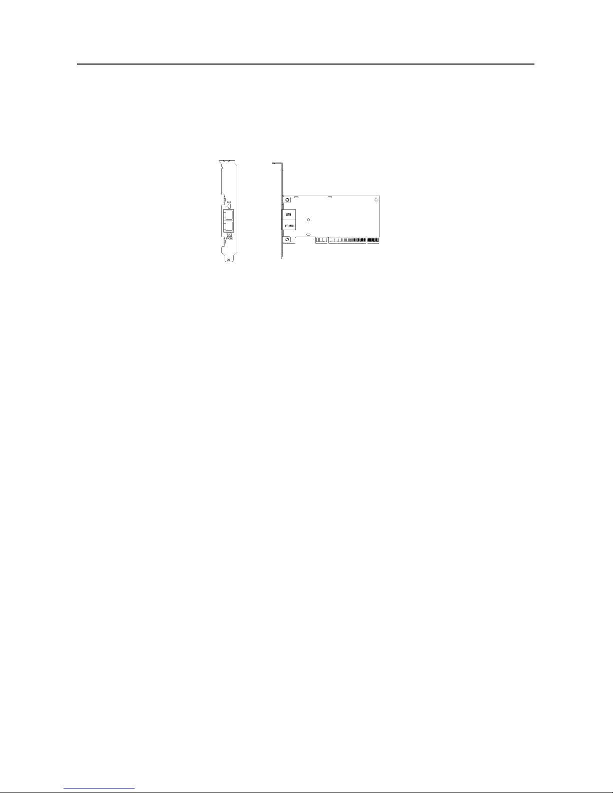
Section 2.2 Hardware Installation
Please refer to Fig. 2 - 1 and pr oceed to follo wing steps for how to ins ert your modem into the com puter and
connect telephone wire and audio accessories.
Model: I206
FIGURE 2-1 Internal modem diagram
1. Turn off and unplug your computer from the AC outlet.
2. Unplug any peripheral devices (keyboard, monitor, etc.) from your computer to a void the
r i s k o f electr ic shock.
3. Take the cover off your computer, review computer's manual if you need further instructions.
4. Find an empty PCI slot.
5. Unscrew the PCI slot bracket and save the screw, then remove the bracket.
6. Plug the modem into the PCI slot carefully until the modem is properly seated.
7. Fasten the modem bracket firmly with the screw saved in step 5.
8. Reassemble your computer cover and re-plug cables for peripheral.
9. Plug one end of telephone cord into th e "LINE" jack at the modem's bracket. Pl ug another end of th e
telephone cord into the telephone wall jack
10. Some m odels m ay com prise a phon e jack f or an optio nal te lephon e. If you wish to us e a phon e thr ough
the same telephone wall j ack when the m odem is not in use, plu g the telephone c ord of the phone into
"PHONE" jack at the modem's bracket no w. L ift the handset and listen for a dial tone to chec k for a
properly connection.
11. Plug the power cord into the computer and turn the computer on.
12. Up to n ow, the hardware installatio n had been f inished. If you have not encounter ed any pro blems, you
can go to Section 2.3 System Setup . If you are having problems, see Section 3 Troubleshooting.
NOTE: The telephone wall jack you use m ust be for an ANALO G phon e line (the type found in m ost hom es).
Many offices are equippe d with di gital pho ne l ines. Pl e as e be s ure you know which type of li ne you ha ve. The
modem will be damaged if you use a digital phone line.
Page 4

I206 V.92 PCI MODEM USER’S M ANUAL
Rev.1.00.2.1.57.75 - 4 -
Section 2.3 System Setup
Section 2.3.1 Setup instructions for Windows 98SE
STEP 1. After you complete the modem hardware installation and turn on your PC, Windows system will
automatically detect your new added devices. Windows system will then prompt you with an Add
New Hardware Wizard screen as shown in figure.
Then click on Next.
STEP 2. A prompt screen will ask you to select Search for the best driver for your device or display a list
of all the drivers in a specific location, so you can select the driver you want.
Please select the recommended one as shown in figure.
Then click on Next.
STEP 3. And then, a prompt screen will ask you to indicate where your driver is located, floppy disk drives,
CD-ROM drive, Microsoft Windows Update or specify a location: .
Insert the Modem Driver CD-ROM disk attached with your modem into the CD-ROM drive device.
Then select Specify a locat ion as shown in figure.
Click on Next.
Page 5

I206 V.92 PCI MODEM USER’S M ANUAL
Rev.1.00.2.1.57.75 - 5 -
STEP 4. Then, a prompt screen indicates Windows has found the best driver for your modem as shown
in figure.
Please make sure the source of your driver is correct then click on Next.
STEP 5. Select International Settings tab as shown in figure.
Make sure the country setting is correct (default United States of America).
Changes of the setting will effect to modem performance.
Please select a correct option to match your location and click OK.
STEP 6. Click on Finish to complete the modem installation.
Page 6

I206 V.92 PCI MODEM USER’S M ANUAL
Rev.1.00.2.1.57.75 - 6 -
Section 2.3.2 Uninstall Modem from Windows 98SE
In any reason, you want to remove or reinstall the modem. Please follow the steps below to completely
uninstall the modem.
STEP 1. Click on Start # Settings # Control Panel as shown in figure.
STEP 2. Click on Add/Remove Programs icon in Control Panel window.
STEP 3. Click Install/Uninstall tab and choose Intel(R) 537EP Modem.
Then click Add/Remove…. Button to uninstall the modem.
Page 7

I206 V.92 PCI MODEM USER’S M ANUAL
Rev.1.00.2.1.57.75 - 7 -
Section 2.3.3 Setup instructions for Windows Me
STEP 1. After you complete the modem hardware installation and turn on your PC, Windows system will
automatically detect your new added devices “PCI Card”.
A prompt screen will ask you to select Automatic search for a better driver or Specify the
location of the driver, so you can select the driver you want.
Please select the Specify the location of the driver [Advanced] as shown in figure.
Then click on Next.
STEP 2. And then, a prompt screen will ask you to indicate where your driver is located, floppy disk drives,
CD-ROM drive, Microsoft Windows Update or specify a location: .
Insert the Modem Driver CD-ROM disk attached with your modem into the CD-ROM drive device,
then select Specify a location as shown in figure.
Click on Next.
STEP 3. Then, a prompt screen indicates Windows has found the best driver for your modem as shown
in figure.
Please make sure the source of your driver is correct then click on Next.
Page 8

I206 V.92 PCI MODEM USER’S M ANUAL
Rev.1.00.2.1.57.75 - 8 -
STEP 4. Then, an Intel(R) 53 7EP Modem Settings screen show International Settings tab as shown in
figure.
Make sure the country setting is correct (default United States of America).
Changes of the setting will effect to modem performance.
Please select a correct option to match your location and click OK.
STEP 5. Click on Finish to complete the modem installation.
Page 9

I206 V.92 PCI MODEM USER’S M ANUAL
Rev.1.00.2.1.57.75 - 9 -
Section 2.3.4 Uninstall Modem from Windows Me
In any reason, you want to remove or reinstall the modem. Please follow the steps below to completely
uninstall the modem.
STEP 1. Click on Start # Settings # Control Panel as shown in figure.
STEP 2. Click on Add/Remove Programs icon in Control Panel window.
STEP 3. Click Install/Uninstall tab and choose Intel(R) 537EP Modem.
Then click Add/Remove…. Button to uninstall the modem.
Page 10

I206 V.92 PCI MODEM USER’S M ANUAL
Rev.1.00.2.1.57.75 - 10 -
Section 2.3.5 Setup instructions for Windows 2000
STEP 1. After you complete the modem hardware installation and turn on your PC. W indows system will
automatically detect your new add ed devices. W indows system will t hen prom pt you with a Found
New Hardware Wizard screen, as shown in figure.
STEP 2. A prompt screen will ask you to select Search for a su itable driver for m y dev ice or dis pla y a list
of all the drivers in a specific location, so you can select the driver you want.
Please select the recommended one as shown in figure.
Click on Next.
STEP 3. And then, a prompt screen will ask you to indicate where your driver is located, floppy disk drives,
CD-ROM drive, Microsoft Windows Update or specify a location:. Please select Specify a
location as shown in figure.
Page 11

I206 V.92 PCI MODEM USER’S M ANUAL
Rev.1.00.2.1.57.75 - 11 -
Insert the Modem Driver CD-ROM disk attached with your modem into the CD-ROM dri ve device
then click on Next.
STEP 4. Then a prompt screen will ask you to locate the driver for your modem as shown in figure.
Please browse the CD-ROM disk directory at <CD-ROM letter>:\drivers\Win2K&XP.
Then click on OK.
STEP 5. Then, a prompt s creen will advis e you and co nfirm the modem’s driver has been found, as sho wn
in figure.
Then click on Next.
STEP 6. The installation wizard will shows a prompt window as below and then click on Yes.
Page 12

I206 V.92 PCI MODEM USER’S M ANUAL
Rev.1.00.2.1.57.75 - 12 -
STEP 7. Click on Finish to complete the modem installation.
STEP 8. Right click on My Computer icon in Desktop window as shown in figure.
Then choose Properties.
STEP 9. Choose Hardware tab and then click on Device Manager…. Button.
Page 13

I206 V.92 PCI MODEM USER’S M ANUAL
Rev.1.00.2.1.57.75 - 13 -
STEP 10. Expand Modems item and right click on Intel(R) 537EP Modem device.
Then choose Properties.
STEP 11. Choose Advanced tab as shown in figure.
Make sure the country/region setting is correct (default United States of America). Changes of
the setting will effect to modem performance. Please select a correct option to match your location
and click OK.
Page 14

I206 V.92 PCI MODEM USER’S M ANUAL
Rev.1.00.2.1.57.75 - 14 -
Section 2.3.6 Uninstall Modem from Windows 2000
In any reason, you want to remove or reinstall the modem. Please follow the steps below to completely
uninstall the modem.
STEP 1. Click on Start # Settings # Control Panel as shown in figure.
STEP 2. Click on Add/Remove Programs icon in Control Panel window.
STEP 3. Choose Intel(R) 537EP Modem and then click on Change/Remove button as shown in figure.
Page 15

I206 V.92 PCI MODEM USER’S M ANUAL
Rev.1.00.2.1.57.75 - 15 -
Section 2.3.7 Setup instructions for Windows XP
STEP 1. After you complete the modem hardware installation and turn on your PC, Windows system will
automatically detect your new added devices.
Choose Install from a list or specific location [Advanced] as shown in figure, then click on Next
button.
STEP 2. Select the directory of modem driver like <CD-ROM letter>:\drivers\Win2K&XP as shown in
figure.
Then click on Next.
STEP 3. The prompt screen will ask you to ensure the driver for your modem as shown in figure.
Click on Continue anyway.
Page 16

I206 V.92 PCI MODEM USER’S M ANUAL
Rev.1.00.2.1.57.75 - 16 -
STEP 4. System has completed the modem driver installation.
Then click on Finish.
STEP 5. Click Start # Control Panel in Taskbar as shown in figure.
STEP 6. Click on Phone and Modem Options icon in Control Panel window as shown in figure.
Page 17

I206 V.92 PCI MODEM USER’S M ANUAL
Rev.1.00.2.1.57.75 - 17 -
STEP 7. Choose Intel(R) 537EP Modem device and click Properties button in Modems tab.
STEP 8. Make sure the country/region setting is correct (default United States) in Advanced tab.
Changes of the setting will effect to modem performance.
Please select a correct option to match your location and click OK.
Page 18

I206 V.92 PCI MODEM USER’S M ANUAL
Rev.1.00.2.1.57.75 - 18 -
Section 2.3.8 Uninstall Modem from Windows XP
In any reason, you want to remove or reinstall the modem. Please follow the steps below to completely
uninstall the modem.
STEP 1. Click Start # Control Panel in Taskbar as shown in figure.
STEP 2. Click on Add or Remove Programs icon in Control Panel window as shown in figure.
STEP 3. Choose Intel(R) 537EP Modem device and the n click on Change/Remove button as shown in
figure.
Page 19

I206 V.92 PCI MODEM USER’S M ANUAL
Rev.1.00.2.1.57.75 - 19 -
Section 2.4 Testing Your Modem
Before you set u p your s oftware, start with a qu ick tes t to check that your modem is wor king. Onc e you have
determined that your m odem is setup properly, go on to Section 2.5 Install Communicat ion Software to
install your communications software. If you are having problems, see Section 3 Troubleshooting.
Click on Start and point to Setting. Then click on Control Panel. When the Control Panel windo w opens .
Scroll down to the M odem icon and double click on it. Click on the Diagnostics tab and highlight the COM
port for your modem. Then click on More Info, your computer will automatically communicate with your new
modem using AT commands and receiving responses from your modem. A list of response means the modem
is setup properly.
Section 2.5 Install Communication Software
Yo u can install the communication s oftware from the CD-ROM disc attached wit h your new modem. Please
consult the software manual in the CD-ROM disc for the detail of software installation.
You do not have to use the communication software attached with your new modem. The modem was
designed for and tested using a wide range of communications software packages. Many communication
applications identify the modem automatically and configure them selves for the correct operating settings.
Some of the com munication applications will ask you to select the t ype of modem you are us ing. Select a
Generic Fax class 1 modem will let you use basic communication and fax functions.
Page 20

I206 V.92 PCI MODEM USER’S M ANUAL
Rev.1.00.2.1.57.75 - 20 -
Section 3 Troubleshooting
Your modem is designed to provide reliable and trouble-free functionality, however, should you experience
any difficulty, the information contained in this section will assist you in determining and resolving the source
of the problem.
Problem: Modem does not respond to AT commands
Possible solutions:
1. Make sure the m odem is not configured with a confl icting COM port and IRQ setting. Make sure the
communication software is configured with the correct COM and IRQ settings (the same COM port
and IRQ as the modem). Your communications software will not be able t o send or receive an y data if it
is not configured to match the COM port and IRQ settings for the modem.
DOS based communication program is not working with this modem neither can you operate the
modem in MS-DOS prompt screen.
2. Make sure the modem is properly initialized using the driver software. The software may improperly
Initialize your m odem because you ha ve selected a n incorrect m odem type. You may also be prompted
to enter an initialization string by the software. Use AT&F as your initialization string.
Problem: Modem dials but does not connect
Possible solutions:
1. Be sure the IRQ setting is identical on the modem and the software.
2. Make sure that the phone line is working properly. A noisy line will prevent proper modem operation.
Problem: Modem makes a connection but no data appears on screen
Possible solutions:
3. Make sure all comm unication par ameter s (baud rate, data, stop, and parit y bits) are pro perly conf igured
and are identical on both sides . Be certain h ardware flow contro l (RTS/CT S - default) is enab led in bot h
the modem and the communication software.
4. Press the ENTER k ey several times. The rem ote system may be waiting to recei ve your data before it
begins.
5. Make sure the correct terminal emulation mode is being used in the software (refer to software manual).
Problem: Modem displays errors while on-line with a remote modem
Possible solutions:
6. Make sure Call Waiting is turned off.
7. Make sure RTS/CTS hardware flow control is enabled (do not use XON/XOFF software flow control
when transferring binary files).
8. Make sure the data speed is not faster than your computer capability. Operating too many applications
Page 21

I206 V.92 PCI MODEM USER’S M ANUAL
Rev.1.00.2.1.57.75 - 21 -
at the same time may cause communication problem. Close unnecessary application in your system.
Problem: Modem exhibits poor voice recording or playback
Possible solutions:
9. Make sure the correct modem type is selected in the Voice/FAX software. Volume adjustment is
available in control panel.
10. Make sure your computer is fast enough to handle voice operations (38.4 Kbps). Voice operations are
CPU intensive and require a better CPU sharing when running under Windows.
Problem: No dial tone
Possible solutions:
11. Ensure that the telephone cord it securely connected at both modem and wall outlet.
12. Unplug the telephone cord from the computer and connect it directly to a telephone from the wall outlet.
Check for a dial tone. If there is none, the problem is in the telephone cord or system. Call your
telephone service provider.
13. Double-check your country setting. Different country setting will cause different modem performance.
Please select the correct country as you located.
14. Check modem performance with a direct line from your tel eph one c ompany. Some PBXs may cause the
telephone line condition change and affect modem performance.
Problem: The modem does not answer incoming calls
Possible solutions:
15. Ensure that the automatic answer parameter is set to one of the enabled options, using the ATS0
command (ATS0=1 to answer after one ring, and so on).
16. Ensure that no other devices, such as fax or answering machines, are answering calls before the
modem does.
If you cannot resolve your situation after reading this section, contact your dealer or vendor for assistance.
Page 22

I206 V.92 PCI MODEM USER’S M ANUAL
Rev.1.00.2.1.57.75 - 22 -
Appendix 1 Modem Specifications
Modulation standard : V.92, V.90, K56 flex, V.34+, V.34, V.32bis , V.32, V.29, V.27ter, V.22bis,
V.23, V.22, V.21, V.17, Bell212/103
Compression : V.42bis, MNP Class 5
Error Correction : V.44, V.42, MNP Class 2-4
Host Interface : PCI bus
FAX Group : Group III
FAX Command : EIA/TIA 578 class 1
Power : 0.75 W max
Temperature : 0 to 55 degrees C, operating; -20 to 75 degrees C, non-operating
Appendix 2 Government compliance notices
FCC compliance
This equipment com plies with Part 6 8 of the FCC Ru les. On this equipm ent is a label that contains, among
other information, the FCC registration number and Ringer Equivalence Num ber (REN) for this equipment.
You must, upon request, provide this information to your telephone company.
If your telephone equipment causes harm to the telephone network, the Telephone Company may
discontinue your service temporarily. If possible, they will notify in advance. But, if advance notice isn’t
practical, you will be notified as soon as poss ible. You wil l b e i nf ormed of your right to file a c omplaint with the
FCC.
Yo ur telephon e company m ay make c hanges in its faci lities, equ ipment, operat ions, or proc edures that c ould
affect proper operation of your equipment. If they do, you will be notified in advance to give you an opportunity
to maintain uninterrupted telephone service.
The FCC prohibits this equipment to be connected to party lines or coin-telephone service.
In the event that t his eq uipment should fail to operat e pr operl y, disconnect the equipm ent fr om the phone line
to determine if it is c ausing the problem. If the probl em is with the equipment, dis continue use and contact
your dealer or vendor.
Page 23

I206 V.92 PCI MODEM USER’S M ANUAL
Rev.1.00.2.1.57.75 - 23 -
FCC Class B statement
This equipment has been tested and found to com ply with the limits for a Clas s B digital dev ice, pursuant to
Part 15 of the FCC Rules. These limits are designed to provide reasonable protection against harmful
interference in a residential installation. This equipment generates, uses and can radiate radio frequency
energy, and if not installed and used in acc ordance with the ins tructions, may caus e harmful interferenc e to
radio communications. However, there is no guarantee that interference will not occur in a particular
installation. If this equi pment does cause harmf ul interference to radio or tele vision reception, wh ich can be
determined by turnin g the equipm ent off and on, the user is encouraged to try to correct the interferenc e by
one or more of the following measures:
Reorient or relocate the receiving antenna.
Increase the separation between the equipment and the receiver.
Connect the equipment into an outlet on a circuit different from that to which the receiver is connected.
Consult the dealer or an experienced radio/TV technician for help.
Notice: 1) Shielded cables, if any, must be used in order to comply with the emission limits.
2) Any change or modification not expressly approved by the Grantee of the equipment
authorization could void the user's authority to operate the equipment.
DOC compliance information
NOTICE: The Canadian D epartment of Communic ations label iden tifies certif ied equ ipment. T his certif ication
means that the equipment meets certain telecommunications network protective, operational and safety
requirements. The Department does not guarantee the equipment will operate to the user’s satisfaction.
Before installing this equipment, users ensure that it is permissible to be connected to the facilities of the local
Telecommunications Company. The equipment must also be installed using an acceptable method of
connection. The customer should be aware that compliance with the above conditions might not prevent
degradation of service in some situations.
Repairs to certified equ ipment should be made by an auth ori zed Canadian maintenance fac i lity designated by
the supplier. Any repairs or alter ations made by the user to this equ ipment, or equi pment malfunc tions, may
give the telecommunications company cause to request the user to disconnect the equipment.
Users should ensure for their own protection that the electrical ground connections of the power utility,
telephone lines and internal metallic water p ipe system, if present, are c onnected together. This precaution
may be particularly important in rural areas.
CAUTION: Users should not attempt to make such connections themselves, but should contact the
appropriate electric inspection authority, or electrician, as appropriate.
Page 24

I206 V.92 PCI MODEM USER’S M ANUAL
Rev.1.00.2.1.57.75 - 24 -
NOTICE: The Load Number (LN) as signed t o eac h t erminal device denotes the perc entage of the tota l load to
be connected to a telephone loop which is used by t he device, t o prevent over loading. The t ermination o n a
loop may consist of any combination of devices subject only to the requirement that the sum of the Lo ad
Numbers of all the devices does not exceed 100.
European CTR 21 compliance
The equipment has been a pproved in accordance wit h Council Decision 98/482/ EC for pan-European single
terminal connection t o the public switched telep hone network (PSTN). Howe ver, due to differences between
the individual PSTNs provided in different countries, the approval does not, of itself, give an unconditional
assurance of succes sful operation on every PSTN n etwork termination point. In the e vent of problem, you
should contact your equipment supplier in the first instance.
Note: The manufac turer should ensure tha t the vendor and user of the equipm ent is clearl y informed of the
above information by means of package and /or user manuals of the forms of user instructions.
 Loading...