

Page 1

Important: Retain these instructions
UNPACKING
INSTALLATION
Installation Instructions
XW/R/IQ
Wireless Sensor Receiver
XW/R/IQ Installation
Instructions TG200783
Dimensions
1
Ø 20 mm
(0.78”)
mounting slot
(1.77”)
45 mm
37 mm
(1.46”)
40 mm
(1.57”)
b
-35 °C
(-31 °F) (+158°F)
c
Note that range may be affected
by environmental characteristics,
e.g. partitions, walls, building
structure etc.
+70 °C
75 m, 80 yds
(maximum)
174 mm (6.85”)
RJ11
plug
4 m
(4 yds 1’)
XW/R/IQ
Requirements
2
a
H O
0 %RH
2
100 %RH
Protection IP68+
d
• Avoid using many other devices on frequency
range 433.05 to 434.79 MHz
• Keep away from sources of interference (e.g.
computer >1 m, 1 yd, microwave ovens, switch
mode power supplies).
• Mount above partition height if possible.
XW/R/IQ Wireless Sensor Receiver Installation Instructions TG200783 Issue 1/B 16/01/07
1
Page 2
XW/R/IQ Installation Instructions
INSTALLATION (continued)
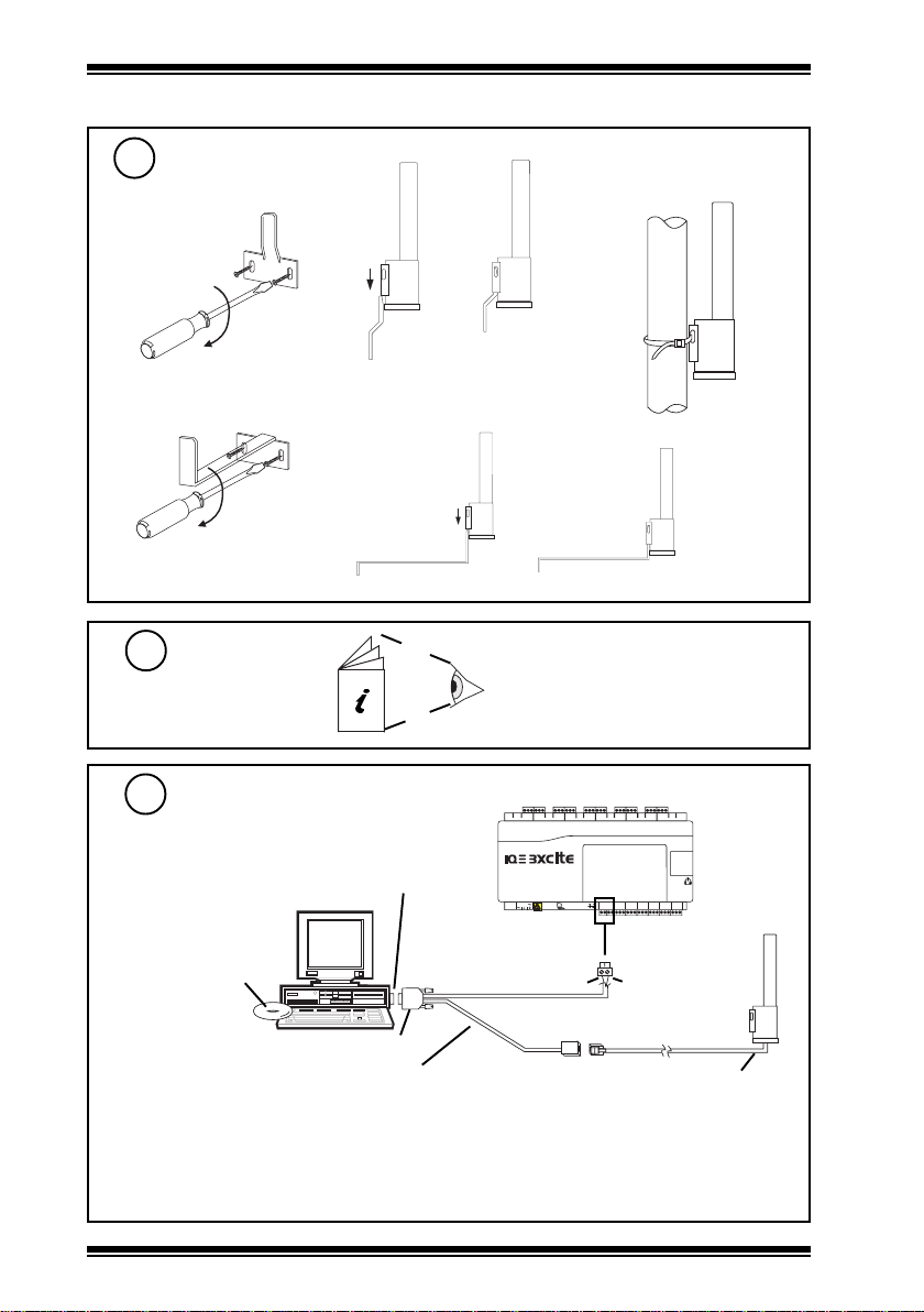
Mount Unit
3
(1) Using plastic bracket supplied
(a) fix bracket (b) (c)
use screws
and rawl plugs
(2) Using stainless steel bracket accessory ACCW/FK/SS
(2) Using cable tie to pipe
(a) (b)
use screws and rawl plugs
Install Sensor(s)
4
Configure Receiver
5
(a) Connect to PC and 24 Vac
RS232 port
XW/R/IQ Configuration
Tool CD (part of
ACCW/CONFIGKIT)
9 way D type female
configuration cable (part of ACCW/CONFIGKIT)
24 Vdc Aux supply out
(c)
TW/S Installation Instructions TG200781
TW/P Installation Instructions TG200782
100-240 V
2 screw terminal
(+24 V) Red Blue (0 V)
RJ11
socket
OK RX
ensure correct
polarity
<=50 mA
RJ11 plug
XW/R/IQ
(b) Check the following settings in XW/R/IQ Configuration Tool:
b1: Port is set to appropriate port number
b2: Protocol is set to Trend Protocol
b3: Read Channels 1-16 (if some channels already set up)
2
XW/R/IQ Wireless Sensor Receiver Installation Instructions TG200783 Issue 1/B 16/01/07
Page 3

Installation Instructions XW/R/IQ
INSTALLATION (continued)
Configure Receiver (continued)
5
TW/.., XW/R/IQ data sheet
TA200780
XW/R/IQ Configuration
Tool Manual TE200793
(c) c1: Select Configuration/Output Mode 0 - All transmitters [Binary]
(configuration software communications window will show communications from sensors)
communications window
configuration software
c2: Select appropriate sensor identification no. from window
e.g. Thermistor Temperature TX.: 16946 Temperature: 26.8
ADC: 367 f/w V4 $---- etc.
sensor’s identification number
Note: if no reception from sensor, see step 6 below.
c3: Type sensor ident ification number into Transmitter Address
slot, and type its Analogue Node Number, and O/S
(outstation) Address into adjacent slots in table
sensor table
(d) Configure Table and PIN (if required) (repeat steps c2, c3 for all sensors)
metItluafeDfiegnahCotegnahCetoN
rebmunNIP4321
rettimsnarT
woRrettimsnarT
0rettimsnartwenputesot
sserddA
eugolanA
000rettimsnartwenputesot
.oNedoN
S/O
0rettimsnartwenputesot
sserddA
evah)s(rellortnoC
putes)s(sdrowssap
'4321'ottnereffid
eS
anA
ocnidesuNIP
)s(rellortn
59=>levelytiroirpfo
noitacifitnedirosn
rosnesmorfrebmun
)stigid
eulav
8(lebalnoitacifitnedi
nirebmunedoneugol
rosneserotsotrellortnoc
nosserddarellortnoC
ebnac(krowtenlacol
htonarorellortnoclacol
re
)krowtennorellortnoc
Notes:
1 If the values from the XW are to be sent to more than one controller, check if passwords (PINs)
set up in any of them. One PIN must be the same in all controllers and of priority level >=95.
2 If sensor value is to be sent to another controller (other than the local controller) the local
supervisor port address must be greater than zero.
PIN
1
1
2
(e) Configure Table into XW
e1 Change Configuration/Output Mode to ‘5 Programmed Transmitter Trend Protocol (ASCII)’
e2 Select Configuration/Programme Channels 1-16
e3 Select Configuration (Read Channels 1-16) and check table is correct
Note that to program channels 17-32 select:
Read Channels 17-32 step b3
Program Channels 17/32 step e2
Read Channels 17-32 step e3
CAUTION
Ensure that the menu item Configuration/Output Mode is set back to ‘5 Programmed Transmitters Trend Protocol (ASCII)’ or the receiver will not operate.
!
(f) Unplug XW/R/IQ receiver from adaptor cable
XW/R/IQ Wireless Sensor Receiver Installation Instructions TG200783 Issue 1/B 16/01/07
3
Page 4

XW/R/IQ Installation Instructions
INSTALLATION (continued)
If there is reception failure of sensor
6
1 Check compliance with step 2 sections C & D
2 Move sensor or receiver slightly in case of a standing wave null position
Configure IQ controller strategy
7
For IQ3 the sensor’s target analogue node must be created
using SET. An example strategy including decoding of
alarm bits is given in the TW/.., XW/R/IQ data sheet
Connect receiver to controller
8
Note XW/R/IQ current consumption <= 50 mA
either for IQ3 or current IQ2xx (excluding IQ251)
current IQ2xx (not IQ251)
or IQ3
TW/.., XW/R/IQ
Data Sheet
TA200780
RJ11
or IQ251 and older IQ2xx’s without 24 V on local supervisor port
cable: RD/SDU-ADAPTOR IQ2xx
Test System
9
e.g. TB/TI/..
XW/R/IQ
Manufactured for and on behalf of the Environmental and Combustion Controls Division of Honeywell Technologies Sàrl, Ecublens, Route
du Bois 37,Switzerland by its Authorized Representative.
Trend Control Systems Limited reserves the right to revise this publication from time to time and make changes to the content hereof
without obligation to notify any person of such revisions or changes.
Trend Control Systems Limited
P.O. Box 34, Horsham, West Sussex, RH12 2YF, UK. Tel:+44 (0)1403 21888 Fax:+44 (0)1403 241608 www.trend-controls.com
Trend Control Systems USA
6670 185th Avenue NE, Redmond, Washington 98052, USA. Tel: (425)897-3900, Fax: (425)869-8445 www.trend-controls.com
100-240 V
RJ11
Δ T
IQ
OK RX
local supervisor port
24 Vdc Aux
local
supervisor
port
DISPOSAL
Do not dispose of with normal household waste.
Do not burn.
IQ251
or older IQ2xx’s
WEEE Directive:
At the end of their useful life
the packaging, product, and
batteries should be disposed
of by a suitable recycling
centre.
4
XW/R/IQ Wireless Sensor Receiver Installation Instructions TG200783 Issue 1/B 16/01/07
 Loading...