

Page 1
Important: Retain these instructions
1 2 3
1
+ 0
4 5 6
2
+ 0
7 8 9
3
+ 0
10 11 12
4
+ 0
8
+ 0
7
+ 0
6
+ 0
13 14 15
5
+ 0
16 17 1819 20 21 22 23 24
1 2 3
1
+ 0
4 5 6
2
+ 0
7 8 9
3
+ 0
10 11 12
4
+ 0
8
+ 07+ 0
6
+ 0
13 14 15
5
+ 0
16 17 18 19 20 21 22 23 24
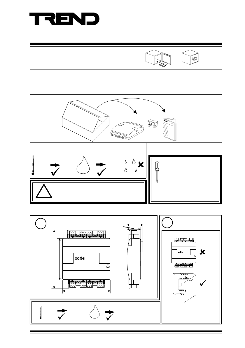
Installation Instructions
XCITE/IO
Standard I/O Module
Contents
1 Unpacking .................................................... 1
2 Storage ......................................................... 1
3 Installation - Mounting .................................. 1
4 Installation - Configuration ......................... 10
5 Disposal ...................................................... 16
1 Unpacking
XCITE/IO Standard I/O
Modules Installation
Instructions TG200627
2 Storage
-10 °C
(14 °F)
+50 °C
(122 °F)
H O
2
WARNING. If the unit is used in a manner other
than that specified in these instructions, the
!
protection provided by the unit may be impaired.
Note that XCITE/IO modules can only be fitted to IQ3XCITE/96/..and /128 (not to IQ3XCITE/16/...,
IQ3XCITE/00/.. or IQ3XACT)
Dimensions
1
1 2 3
4 5 6
7 8 9
3
1
2
+ 0
+ 0
+ 0
0
10 11 12
+ 0
90 %RH
46 mm (1.8”)
42 mm (1.65”)
4
3 Installation - Mounting
It is recommended that the
installation should comply
with the HSE Memorandum
of Guidance on Electricity at
Work Regulations 1989.
For USA install equipment in
accordance with National Electric
Code
Requirements
2
a
130 mm (5.12”)
150 mm (5.91”)
+ 0
5
13 14 15
+ 0
+ 0
+ 0
7
6
16 17 18 19 20 21 22 23 24
8
130 mm (5.12”)
b
0 °C
(32 °F)
XCITE/IO Standard I/O Module Installation Instructions TG200627 Issue 2/E 06/12/07
+45 °C
(113 °F)
90 %RH
0
H O
2
Protection:
IP20, NEMA1
The unit is UL rated as ‘UL916
listed accessory to open energy
management equipment’.
1
Page 2
XCITE/IO Installation Instructions
V
N
3 Installation - Mounting (continued)
4 5 6
1 2 3
7 8 9
Requirements (continued)
2
e
10 11 12
3
1
2
4
+ 0
+ 0
+ 0
+ 0
c
3
a
5
4 5 6
1 2 3
7 8 9
10 11 12
3
1
2
4
+ 0
+ 0
+ 0
+ 0
+ 0
+ 0
+ 0
+ 0
5
7
6
8
13 14 15
16 17 1819 20 21 22 23 24
4 5 6
1 2 3
7 8 9
10 11 12
3
1
2
4
+ 0
+ 0
+ 0
+ 0
+ 0
+ 0
+ 0
+ 0
5
7
6
8
13 14 15
16 17 1819 20 21 22 23 24
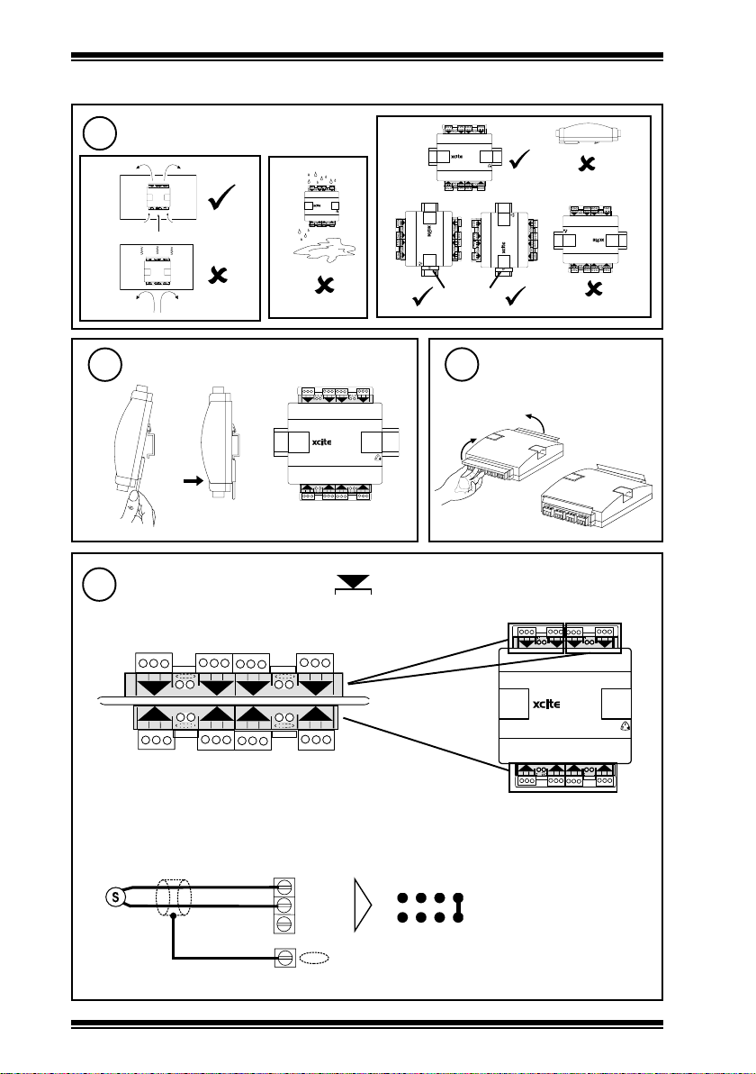
Mounting
b
Connect Universal Inputs
d
4 5 6
1 2 3
7 8 9
10 11 12
3
1
2
4
+ 0
+ 0
+ 0
+ 0
+ 0
+ 0
+ 0
+ 0
5
7
6
8
13 14 15
16 17 1819 20 21 22 23 24
c
1 2 3
1
+ 0
+ 0
5
13 14 15
4 5 6
7 8 9
3
2
+ 0
+ 0
+ 0
+ 0
7
6
16 17 18 19 20 21 22 23 24
XCITE/IO/8UI channels 1 to 8, ../4UI channels 1 to 4
../4UI/4AO, channels 1 to 4, ../2UI/2AO channels 1 to 2
1 2 3
+ 0
+ 0
13 14 15
4 5 6
1
+ 0
+ 0
5
16 17 18 19 20 21 22 23 24
7 8 9
2
+ 0
+ 0
6
10 11 12
3
7
+ 0
+ 0
4
8
+ 0
+ 0
+ 0
+ 0
5
7
6
8
13 14 15
16 17 1819 20 21 22 23 24
13 14 15
+ 0
+ 0
1 2 3
5
1
4
8
+ 0
+ 0
16 17 1819 20 21 22 23 24
+ 0
6
+ 0
7
+ 0
8
10 11 12
+ 0
4 5 6
2
3
7
7 8 9
+ 0
+ 0
7 8 9
3
10 11 12
+ 0
4
+ 0
2
6
4 5 6
+ 0
+ 0
16 17 1819 20 21 22 23 24
1
5
1 2 3
+ 0
+ 0
13 14 15
DIN rail
end stop
Lift I/O terminal
4
10 11 12
4
+ 0
+ 0
8
covers
(Universal input I/O modules only)
1 2 3
1
+ 0
16 17 1819 20 21 22 23 24
13 14 15
8
7
6
5
+ 0
+ 0
+ 0
+ 0
+ 0
+ 0
+ 0
+ 0
4
2
1
3
10 11 12
7 8 9
1 2 3
4 5 6
4 5 6
7 8 9
10 11 12
3
2
4
+ 0
+ 0
+ 0
8UI
Trend TP/1/1/22/HF/200 (Belden 8761) cable recommended for
all inputs.
Cable size 0.5 to 2.5 mm
2
(14 to 20 AWG) - Cu only
+ 0
5
13 14 15
+ 0
+ 0
+ 0
7
6
16 17 18 19 20 21 22 23 24
8
EN61010:2001 MEASUREMENT CATEGORY 1.
Separate from 230 Vac supply by double or reinforced insulation
Voltage input
0 (0 V)
(0 to 10V)
2
+ (+24V)
XCITE/IO Standard I/O Module Installation Instructions TG200627 Issue 2/E 06/12/07
N (in)
N
linking
Note that setting input links is
described in Installation
Instructions - section 4 step 6.
V
Page 3

Installation Instructions XCITE/IO
SIG
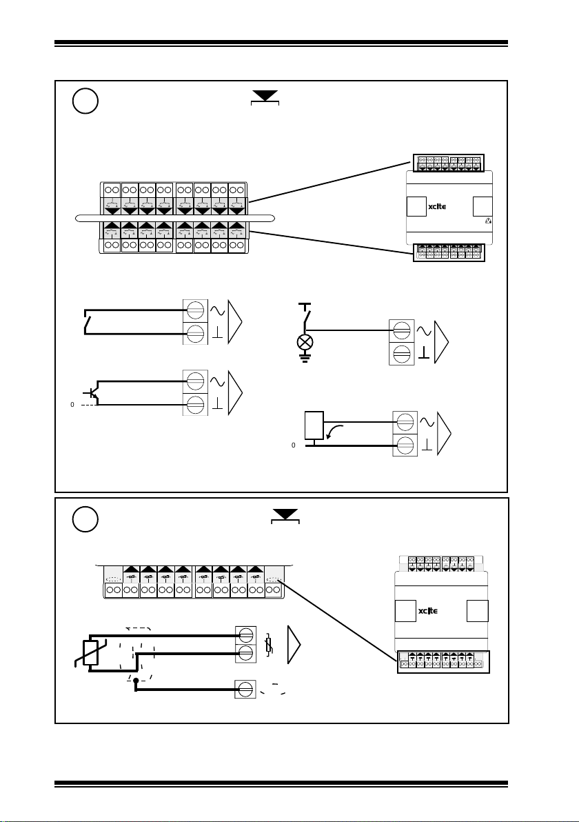
3 Installation - Mounting (continued)
Connect Universal Inputs (continued)
5
Current input (loop powered)
®
(0 to 20 mA)
1
0 (0 V)
N (in)
+ (+24V)
linking
N
I
(20 to 36 V)
Current input (external powered)
0V
SIG
®
(0 to 20 mA)
1
Thermistor input
0V
Digital input
Segregate Screen Earths (Grounds)
6
(Universal input I/O modules only)
0 (0 V)
N (in)
+ (+24V)
0 (0 V)
N (in)
+ (+24V)
0 (0 V)
N (in)
+ (+24V)
N
5 V bridge supply
N
5 V supply
N
linking
I
linking
T
linking
D
if required to segregate screen earths (grounds) from I/O module earth (ground)
1 2 3
4 5 6
7 8 9
10 11 12
3
1
2
4
+ 0
+ 0
8UI
+ 0
+ 0
7
6
16 17 18 19 20 21 22 23 24
+ 0
+ 0
8
Separate earth (ground) connection
Note that screen earth (ground)
link(s) must be cut (see section 4
step 7)
1 2 3
+ 0
terminal size 0.5 to 2.5 mm2 (14 to 20 AWG)
+ 0
1
4 5 6
2
+ 0
+ 0
5
13 14 15
XCITE/IO Standard I/O Module Installation Instructions TG200627 Issue 2/E 06/12/07
3
Page 4
XCITE/IO Installation Instructions
1 213 425 637 849 10511 12613 14715 16
8
17 18 19 20 21 22
131415 16
9
10
11 12
23 24 25 26 27 28 29 30 31 32
N
0
0
N
17 18
19 20
21 22
13
14
15 16
9
10
11 12
23 24
25 26
27 28
29 30
31 32
T
T T TT T
T
T
12134256
3
78
4
910511 12613 14715 16
8
T
17 1817 18
19 2019 20 21 222122
131415 16
9
10
11 12
23 2423 24 252625 26 27 2827 28 29 3029 30 31 3231 32
T
T T TT TTT
121 21343 42565 6
3
787 8
4
9109 10511 1211 12613 1413 14715 1615 16
8
8DI/8TI
3 Installation - Mounting (continued)
Connect Digital Inputs
7
XCITE/IO/16DI channels 1 to 16, ../8DI channels 1 to 8
(Digital input I/O modules only)
Trend TP/1/1/22/HF/200 (Belden 8761) cable recommended for all inputs
EN61010:2001 MEASUREMENT CATEGORY 1.
Separate from 230 Vac supply by double or reinforced insulation
1 213 425 637 849 10511 12613 14715 16
9
10
11 12
17 18 19 20 21 22
23 24 25 26 27 28 29 30 31 32
Cable size 0.5 to 2.5 mm
Volt free contact input
13
2
(14 to 20 AWG) - Cu only
8
15 16
14
24 Vac input
24 Vac ±20%
N
Load
Open collector type input
Logic input
V
N
logic high = 5 to 50 V
logic low = sink >3 mA
e . g .
T T L
C M O S
3 m A
V
Note that logic low on input
produces ON state in IQ3
16DI
N
N
Connect Thermistor Inputs
8
XCITE/IO/8DI/8TI channels 9 to 16
Trend TP/1/1/22/HF/200 (Belden 8761) cable recommended for all inputs
19 20
21 22
17 18
23 24
25 26
27 28
29 30
31 32
N
0V
4
XCITE/IO Standard I/O Module Installation Instructions TG200627 Issue 2/E 06/12/07
(Thermistor input I/O modules only)
Page 5
Installation Instructions XCITE/IO
1
2
3
6
2
24 V
P
13 14 15
5
P 0
16 17 18
6
P 0
19 20 21
7
P 0
22 23 24
8
P 0
24 V
P
1 2 3
1
P 0
4 5 6
2
P 0
7 8 9
3
P 0
10 11 12
4
P 0
N
3 Installation - Mounting (continued)
Connect Analogue Outputs
9
(Analogue output I/O modules only)
XCITE/IO/4UI/4AO, channels 5 to 8, ../2UI/2AO channels 5 to 6
../8AO, channels 1 to 8, ../4AO channels 1 to 4
Trend TP/1/1/22/HF/200 (Belden 8761) cable recommended for analogue outputs
If screened cable is used, terminate screen to earth at one end
EN61010:2001 MEASUREMENT CATEGORY 1.
Separate from 230 Vac supply by double or reinforced insulation
1 2 3
4 5 6
7 8 9
P
24 V
P 0
P 0
1
2
5
P 0
16 17 18
6
P 0
P
13 14 15
24 V
Cable size 0.5 to 2.5 mm
10 11 12
P 0
P 0
3
4
7
P 0
19 20 21
2
(14 to 20 AWG) - Cu only
8
P 0
22 23 24
8AO
(0 V)
(0 to 10 Vdc, <=20 mA)
(+24 V)
optional
LOAD
N
(out) N
0
P
If P terminal used, P input terminal must be
connected as in step 10 below.
WARNING
If external supply is used to supply P input
terminal, note whether P bus is 24 Vac or 24 Vdc
and only connect appropriate devices to P output
terminals.
Additional Relay Modules
xcite I/O
Module
N
Relay
Module
SRMV =
2SRM =
2RM =
3RM =
6RM =
nRM
x
x
x
x
x
e.g.
SRMAC
Analogue
outputs are
IQ3
0
SRMV
not suitable
for ac relays
P
XCITE/IO Standard I/O Module Installation Instructions TG200627 Issue 2/E 06/12/07
5
Page 6

XCITE/IO Installation Instructions
A
A
31 32 33
P
11
P 0
3 Installation - Mounting (continued)
Connect Output Power (P)
10
If (P) used in step 9 above
Check current availability from I/O bus
connector 24 Vdc terminal and from 24 Vdc
auxiliary supply:
P
24 V
P
24 V
either use I/O module 24 Vdc auxiliary supply
current <= 150 mA
5
P 0
13 14 15
P
24 V
Fit external link
Note that the 24 Vdc auxiliary supply is normally
about 19.8 V and drops to about 18.4 V at full
load.
(Analogue output I/O modules only)
IQ3 Data Sheet TA200505
1 2 3
4 5 6
7 8 9
10 11 12
P 0
P 0
P 0
P 0
1
2
3
4
8AO
5
6
7
P 0
13 14 15
8
P 0
P 0
P 0
19 20 21
22 23 24
16 17 18
terminal size 0.5 to 2.5 mm
(14 to 20 AWG)
or use 24 Vdc or 24Vac external supply
P 0
24 V
24 V
0V
PSU
External PSU
WARNING
External PSU must be dedicated to I/O
channel use, and comply with relevant
EMC and safety standards
2
Note if P bus is 24 Vdc or 24 Vac, and only connect appropriate devices to P output terminals
in step 9 above
6
XCITE/IO Standard I/O Module Installation Instructions TG200627 Issue 2/E 06/12/07
Page 7

Installation Instructions XCITE/IO
N
NO
NC
C
N
POWER
Actuator
NO
NC
C
N
R
L
C
Raise
Lower
Common
O
I
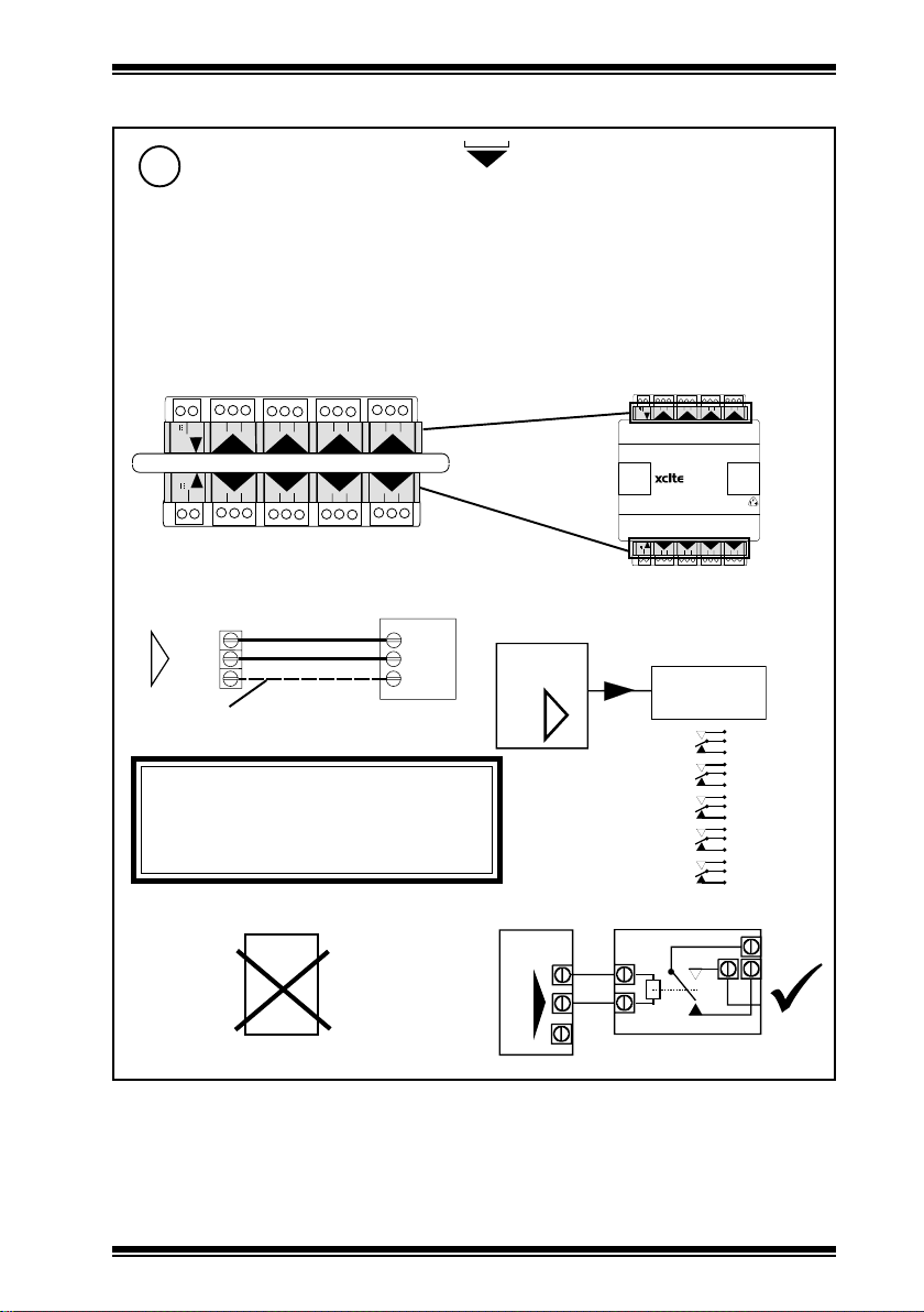
3 Installation - Mounting
Connect Relay Outputs
11
(Relay output I/O modules only)
XCITE/8DO, ../8DO/HOA channels 1 to 8, ../4DO, ../4DO/HOA channels 1 to 4
5A maximum at 240 Vac, single phase throughout, resistive or inductive (Cos Ø>=0.4)
5 A at 30 Vdc (resistive), 2 A at 24 Vdc (inductive, T<=30 ms)
Note that the UL rating applies up to 240 V 120 VA maximum
1 2 3
4 5 6
NC C
NC C
1
5
C NC
C NC
13 14 15
NC
N
Æa
C
NC
N
C
Æb
N
Driver on, Load on
NC
NO
N
C
2
6
16 17 18
NC
NO
C
7 8 9
NC C
3
7
C NC
19 20 21
LOAD
(continued)
10 11 12
NC C
4
8
C NC
22 23 24
NC
N
C
NC
N
C
Æa
Æa
1 2 3
4 5 6
10 11 12
NC C
C NC
13 14 15
7 8 9
NC C
NC C
1
2
3
8DO
5
6
7
C NC
C NC
16 17 18
19 20 21
Cable size 0.5 to 2.5 mm
NC C
4
(14 to 20 AWG) - Cu only
8
C NC
22 23 24
WARNING: The wires may be
connected to hazardous
voltages. Disconnect
power before attempting
any wiring.
Arc suppression
recommended
Relay Output Arc Suppression
Installation Instructions TG200208
2 outputs - Raise/Lower
2
POWER
Driver off, Load
NC
on
NO
N
C
POWER
LOAD
Install IQ3xcite Controller
12
(IQ3XCITE/96/... only)
IQ3xcite Installation
Instructions, TG200626
- Section 3 steps 1 to
11 only
XCITE/IO Standard I/O Module Installation Instructions TG200627 Issue 2/E 06/12/07
DO NOT SWITCH ON
7
Page 8

XCITE/IO Installation Instructions
+24 Vdc
0 V
Data Hi
Data Lo
+24 Vdc
0 V
Data Hi
Data Lo
Ground
Ground
Red
White
Blue
Black
!
"
#
#
"
!
3 Installation - Mounting (continued)
Connect I/O Bus
13
• A maximum of 15 I/O modules can be connected.
• A maximum of 96 points (on IQ3XCITE/96) or 128 points (on IQ3XCITE/128) can be used:
16 points in the IQ3xcite and 80 or 112 expansion points.
• The maximum bus length is 30 m (rigid interconnectors can be ignored).
• The controller and its I/O modules are to be fitted inside enclosures
• No spurs are allowed on the I/O bus
• If a single earth (ground) screened and bonded contiguous metal enclosure is used, then
total I/O bus length can be up to 30 m (includes use of multisection panels e.g. Form 4 enclosures)
If any other type of enclosure is used, or
I/O bus runs between enclosures, then total
I/O bus cable length can be up to 10 m.
(For cable length calculation, rigid
interconnectors can be ignored)
• Mutiple enclosures must be earthed
(grounded) to a common earth (ground)
point (according to latest IEE Regs).
b
either use XCITE/IC interconnector (supplied with I/O module)
4 5 6
16 17 18
13 14 15
1 2 3
10 11 12
7 8 9
3
5
6
1
2
4
+ 0
+ 0
+ 0
+ 0
+ 0
+ 0
19 20 21
+ 0
a
22 23 24
7
+ 0 + 0 + 0
8
25 26 27
28 29 30
10
9
Open flaps
4 5 6
1 2 3
7 8 9
10 11 12
3
1
2
4
+ 0
+ 0
+ 0
+ 0
100-240 V
13
11
12
P 0
P 0
P 0
OK RX
34 35 36
31 32 33
37 38 39
P
24 V
24 V
0 V
6
16
15
14A
P 0
P 0
43 44 45
40 41 42
7
5
8
P 0
P 0
P 0
P 0
46 47 48
P 0
22 23 24
16 17 18
19 20 21
P
13 14 15
24 V
XCITE/IC interconnector (supplied)
(XCITE/IC/5, pack of 5 available separately)
or wire special cable using XCITE/CC connectors and Belden 3084A cable
DIN rails must be earthed (grounded)
cable type A
XCITE/CC connectors
Order separately (XCITE/CC/10, pack of 10)
Belden 3084A cable
XCITE/CC connectors
Order separately (XCITE/CC/10, pack of 10)
cable type B
right to right
!
"
#
Data Hi
Ground
Data Lo
0 V
White
Blue
Black
Red
+24 Vdc
Belden 3084A cable
Red
White
Blue
Black
Signal direction
cable type B
left to left
DIN rails must be earthed (grounded)
8
XCITE/IO Standard I/O Module Installation Instructions TG200627 Issue 2/E 06/12/07
+24 Vdc
#
Data Hi
"
Ground
!
Data Lo
0 V
+24 Vdc
Data Hi
Ground
!
Data Lo
"
0 V
#
connector rotated
through 180°
+24 Vdc
#
Data Hi
"
Ground
!
Data Lo
0 V
Page 9

Installation Instructions XCITE/IO
L+
L+
LL-
L
N
DC
ADJ.
IN
L+
L+
LL-
L
N
DC
ADJ.
IN
3 Installation - Mounting (continued)
Connect I/O Bus (continued)
13
Fully screened and bonded
contiguous multi section cabinet
type B
PSR
type A
An additional 24 Vdc ±15% power supply must be used to supply the IO modules if:
•There are more than 6 I/O modules (except for 16/DI, /8DI, /8DI/8TI, /8AO, /4DO/HOA,
/8DO/HOA, /4AO, /4DO (serial No. >= M3D4 CO 508 012), /8DO (serial No. >= M3D8 CO 508
0136); which do not need to be included in the count).
or • The main controller 24 Vdc combined supply would be overloaded
WARNING: External PSU must have
isolated output and comply with
relevant EMC and safety standards
external PSU with isolated output
XCITE/PCON/50, for
adjacent modules available,
order separately (modules
separated by 10 mm)
+24 Vdc
!
"
#
Data Hi
Ground
Data Lo
0 V
White
Blue
Black
Black
24 Vdc
PSU
external PSU with isolated output
XCITE/PCON/1000, 1 metre
cable (type A) available,
order separately
Red
+24 Vdc
#
Data Hi
"
Ground
!
Data Lo
0 V
Check IQ3xcite 24 Vdc combined
supply output current availability:
IQ3 Data Sheet TA200505
+24 Vdc
Data Hi
!
"
#
White
Ground Ground
Data Lo
Blue
0 V
Black
PSR
type B
Black
24 Vdc
PSU
terminator
Red
+24 Vdc
Data Hi
Data Lo
0 V
#
"
!
Trend can supply the PSR range of DIN rail mounted
auxiliary power supplies (e.g. 1.3 A, 2.5 A, or 5A).
They have isolated outputs.
230 Vac input
power supply
L
N
IN
PSR
Red
DC
ADJ.
L+
L+
LL-
Black
Black
White
Blue
PSR connection to left side
WARNING: Ensure maximum current
passing through any I/O module’s 24 Vdc
terminal is < 1.6 A.
E.g.
#
"
!
IQ3
Groups supplied
separately.
Each group <1.6 A
230 Vac input power
supply
Blue
Black
White
!
"
#
Red
Black
DC
ADJ.
L
N
PSR
L+
L+
LL-
IN
c
Close flaps
PSR connection to right side
XCITE/IO Standard I/O Module Installation Instructions TG200627 Issue 2/E 06/12/07
24 Vdc
(<1.6A)
PSU
(5A)
(<1.6A)
(<1.6A)
module
module
module
I/O
I/O
module
I/O
module
I/O
I/O
module
I/O
I/O
module
module
I/O
I/O
I/O
module
module
I/O
I/O
I/O
module
module
module
9
Page 10

XCITE/IO Installation Instructions
3 Installation - Mounting (continued)
Terminate I/O Bus
14
on I/O module at opposite end of I/O bus from main IQ3xcite controller
Open flap
a
15
XCITE/TERM terminator (supplied with controller)
(XCITE/TERM/5, pack of 5 available separately)
Lower I/O Terminal Covers
Plug in terminator
b
c
Close flap
a
4 Installation - Configuration
Switch Off
1
O
I
also isolate I/O of controller and any
adjacent I/O modules
Open Panel
3
100-240 V
4 5 6
1 2 3
7 8 9
3
1
2
+ 0
+ 0
+ 0
b
Isolate I/O
2
WARNING: The
connecting leads may
be connected to
supplies. Isolate before
touching.
16 17 18
13 14 15
19 20 21
25 26 27
10 11 12
22 23 24
28 29 30
5
6
8
9
10
4
7
+ 0
+ 0 + 0+ 0
+ 0
+ 0
+ 0
A
16
13
11
12
14A
P 0
P 0
P 0
P 0
P 0
P 0
OK RX
34 35 36
31 32 33
37 38 39
43 44 451546 47 48
40 41 42
P
24 V
24 V
0 V
Disconnect I/O
4
O
4 5 6
1 2 3
7 8 9
2
+ 0
16 17 18 19 20 21 22 23 24
7 8 9
3
2
+ 0
10 11 12
3
4
+ 0
+ 0
+ 0
+ 06+ 0
7
8
10 11 12
4
+ 0
1
+ 0
+ 0
5
13 14 15
4 5 6
1 2 3
1
+ 0
+ 0
I
O
I
WARNING: Opening the panel may
expose dangerous voltages.
417-IEC-5036
10
+ 0
+ 0
+ 0
+ 0
5
7
6
8
13 14 15
16 17 18 19 20 21 22 23 24
XCITE/IO Standard I/O Module Installation Instructions TG200627 Issue 2/E 06/12/07
Page 11

Installation Instructions XCITE/IO
4 Installation - Configuration (continued)
Remove Covers
5
a
bcd e
Select Universal Input Channel Type
6
XCITE/IO/8UI channels 1 to 8, ../4UI channels 1 to 4
../4UI/4AO, channels 1 to 4, ../2UI/2AO channels 1 to 2
linking
D (digital)
V (voltage)
T (thermistor)
I (current)
either loop powered (IL), or external powered (Ix)
Cut Screen Earth (Ground) Link(s)
7
(Universal input I/O Modules only)
If screen earth (ground) segregated from I/O
module earth (ground) (see section 3 step 6)
(Universal input I/O Modules only)
8UI
8UI
screen earth (ground) link(s)
XCITE/IO Standard I/O Module Installation Instructions TG200627 Issue 2/E 06/12/07
11
Page 12

XCITE/IO Installation Instructions
O
I
4 Installation - Configuration (continued)
Set I/O Address
8
Address = 1, 2, 3, 4, 5, 6, 7, 8,
0
F
1
2
E
3
D
C
Note that the I/O module needs to be set up (i.e. SET, Device-I/O Setup); the module ID (address),
and its type need to be entered before the module can be used- see IQ3XCITE Installation
Instructions TG200626 section 4 step 22.
Replace Covers
9
a
bc
9, A, B, C, D, E, F
4
5
B
6
7
A
8
9
(Address 0 = disabled)
Address = X
= X
= X
1 2 3
1
+ 0
= X
4 5 6
7 8 9
10 11 12
3
2
4
+ 0
+ 0
+ 0
+ 0
+ 0
+ 0
+ 0
5
7
6
16 17 18 19 20 21 22 23 24
8
Configure IQ3xcite Controller
10
11
13 14 15
Switch On
IQ3xcite Installation
Instructions - TG200626,
Configuration, section 4 steps 1
to 26
Check for Digital Input Misconnection
12
(Digital input I/O modules only (-/16DI, /8DI, /8DI/8TI) with ac input)
1 213 425 6
9 10511 12613 14715 16
7 8
3
8
4
channels 1 to 8
Input
Polarity
(red)
16DI
channels 9 to 16
Check each ac input connection is
either isolated from ground or has
131415 16
9
10
11 12
17 18 19 20 21 22
23 24 25 2627 28 29 30 31 32
12
XCITE/IO Standard I/O Module Installation Instructions TG200627 Issue 2/E 06/12/07
correct side groundeded with respect
to IQ3 ground
Page 13

Installation Instructions XCITE/IO
4 Installation - Configuration (continued)
Check Module
13
1 2 3
+ 0
+ 0
13 14 15
1 2 3
+ 0
1
5
4 5 6
1
2
+ 0
4 5 6
7 8 9
3
2
+ 0
+ 0
+ 0
+ 0
7
6
16 17 18 19 20 21 22 23 24
16 17 18
13 14 15
19 20 21
10 11 12
7 8 9
3
5
6
4
7
+ 0
+ 0
+ 0
+ 0
+ 0
22 23 24
8
+ 0 + 0 + 0
10 11 12
4
+ 0
+ 0
8
c
(I/O bus)
(red)
25 26 27
28 29 30
4 5 6
1 2 3
7 8 9
10
9
10 11 12
3
1
2
4
+ 0
+ 0
+ 0
+ 0
a
b
1 2 3
+ 0
1
4 5 6
7 8 9
3
2
+ 0
+ 0
(power)
(green)
(watchdog)
(red)
10 11 12
4
+ 0
I/O Module Faulty
I/O bus fault (check short circuit, Data
Hi or Data Lo to either power line)
I/O bus comms fault
1s
1s
Address=0 (disabled)
or Address clash
fast
100-240 V
13
11
12
14A
P 0
P 0
P 0
P 0
OK RX
34 35 36
31 32 33
37 38 39
40 41 42
P
24 V
24 V
0 V
Switch off power
Disconnect farthest I/O module
6
16
15
5
P 0
P 0
P 0
P 0
P 0
43 44 45
46 47 48
16 17 18
19 20 21
P
13 14 15
24 V
6
7
P 0
22 23 24
7
8
5
8
P 0
P 0
P 0
P 0
22 23 24
16 17 18
19 20 21
P
13 14 15
24 V
disconnect
Move terminator
Switch on power
Check
(I/O) light
Repeat to isolate faulty module
Replace faulty module or
connection
if address clash
= X
Address = X
= X
Repeat step 8 above until LED extinguishes
Note that the if the I/O module address is changed,
it also needs to be changed in the IQ3xcite
configuration file (i.e. SET, Device-I/O Setup)
before the module can be used- see IQ3xcite
installation Instructions TG200626 section 4
step 22.
XCITE/IO Standard I/O Module Installation Instructions TG200627 Issue 2/E 06/12/07
= X
Address = X
= X
13
Page 14

XCITE/IO Installation Instructions
S
xcite
xcite
1
1 2 3
NC C
2
4 5 6
NC C
3
7 8 9
NC C
4
10 11 12
NC C
5
13 14 15
C NC
6
16 17 18
C NC
7
19 20 21
C NC
8
22 23 24
C NC
4 Installation - Configuration (continued)
Commission Module
14
Access webpages’ I/O modules to check module
type and operational status
Set up PC’s IP
addressing
Web Browser
IQ3xcite
Test Inputs
16
Switch off
a
b
4 5 6
1 2 3
7 8 9
10 11 12
3
1
2
4
+ 0
+ 0
+ 0
+ 0
O
I
Test HVAC Equipment and Wiring
17
+ 0
13 14 15
5
+ 0
+ 0
7
6
16 17 18 19 20 21 22 23 24
+ 0
8
if XCITE/IO/8DO/HOA or../4DO/HOA
Switch on
c
Lift I/O Terminal Covers
15
d
O
I
(yellow)
ΔT = X
1 2 3
1
+ 0
+ 0
5
13 14 15
4 5 6
7 8 9
3
2
+ 0
+ 0
+ 0
+ 0
7
6
16 17 1819 20 21 22 23 24
10 11 12
4
+ 0
+ 0
8
Note that interlocks provided by the strategy will not necessarily be operative when using manual
overrides. It is the system designer’s responsibility to ensure that adequate interlock protection
is provided.
1 2 3
output LEDs
override LEDs
override LEDs
output LEDs
7 8 9
H
A
O
8DO
H
A
O
C NC
C NC
16 17 18
19 20 21
H
A
O
H
A
O
14
XCITE/IO Standard I/O Module Installation Instructions TG200627 Issue 2/E 06/12/07
output (yellow)
override (red)
override (red)
output (yellow)
Page 15

Installation Instructions XCITE/IO
4 Installation - Configuration (continued)
Test HVAC Equipment and Wiring (Continued)
17
a
Switch into
(Hand, manual ON) - check load ON
H
- output (yellow)
H
A
O
Switch into O (manual OFF) - check load OFF
b
H
A
O
Switch into A (Automatic) - check override LED OFF
c
H
A
O
- override (red)
load
- output (yellow)
- override (red)
load
- output (yellow)
- override (red)
load
or
or
Test Outputs
18
Switch off
a
b
1 2 3
4 5 6
10 11 12
7 8 9
NC C
NC C
NC C
NC C
1
2
3
4
O
I
5
6
7
8
C NC
C NC
C NC
C NC
13 14 15
16 17 18
19 20 21
22 23 24
Switch on
c
S
O
I
XCITE/IO Standard I/O Module Installation Instructions TG200627 Issue 2/E 06/12/07
d
1 2 3
4 5 6
7 8 9
10 11 12
P
24 V
P 0
P 0
P 0
P 0
1
2
3
xcite
(yellow)
xcite
(yellow)
4
5
6
7
8
P 0
P 0
P 0
P 0
P
19 20 21
22 23 24
13 14 15
16 17 18
24 V
1 2 3
4 5 6
10 11 12
7 8 9
NC C
NC C
NC C
NC C
1
2
3
4
5
6
7
8
C NC
C NC
C NC
C NC
13 14 15
16 17 18
19 20 21
22 23 24
15
Page 16

XCITE/IO Installation Instructions
4 Installation - Configuration (continued)
Lower I/O Terminal Covers
19
5 Disposal
WEEE Directive :
At the end of their useful life the packaging
and product should be disposed of by a
Do not dispose of with normal household waste.
Do not burn.
suitable recycling centre.
Close Panel
20
4 5 6
1 2 3
7 8 9
10 11 12
3
1
2
4
+ 0
+ 0
+ 0
+ 0
+ 0
+ 0
+ 0
+ 0
5
7
6
8
13 14 15
16 17 1819 20 21 22 23 24
The unit is UL rated as ‘UL916 listed
accessory to open energy
management equipment’.
Please send any comments about this or any other Trend technical publication to techpubs@trendcontrols.com
Manufactured for and on behalf of the Environmental and Combustion Controls Division of Honeywell Technologies Sàrl, Ecublens,
Route du Bois 37,Switzerland by its Authorized Representative, Trend Control Systems Limited.
©Trend Control Systems Limited 2007. Trend Control Systems Limited reserves the right to revise this publication from time to time and
make changes to the content hereof without obligation to notify any person of such revisions or changes.
Trend Control Systems Limited
P.O. Box 34, Horsham, West Sussex, RH12 2YF, UK. Tel:+44 (0)1403 21888 Fax:+44 (0)1403 241608 www.trend-controls.com
Trend Control Systems USA
6670 185th Avenue NE, Redmond, Washington 98052, USA. Tel: (425)897-3900, Fax: (425)869-8445 www.trend-controls.com
16
XCITE/IO Standard I/O Module Installation Instructions TG200627 Issue 2/E 06/12/07
 Loading...