

Page 1
Installation Instructions
WS/R
Rain Detector
Important: Retain these instructions
INSTALLATION
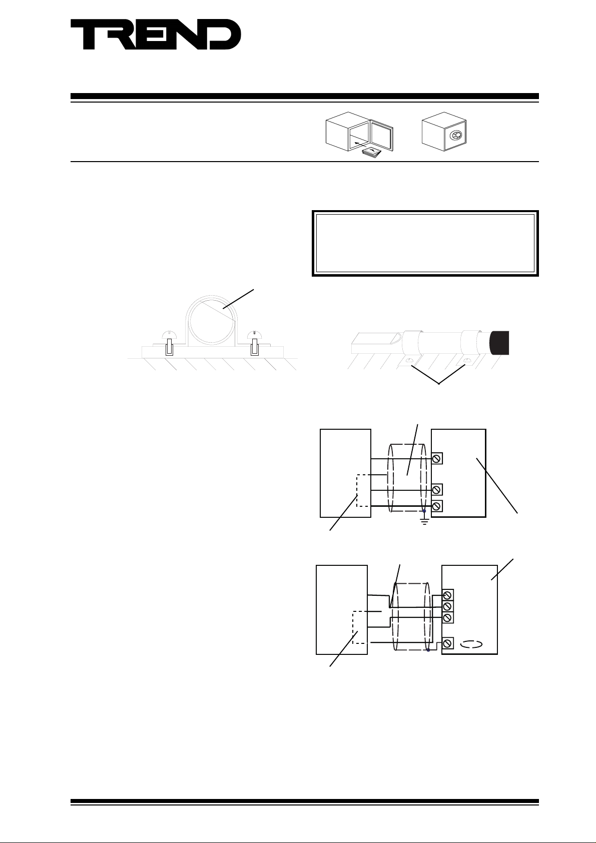
Mount the sensor in position. The location should provide safe access for maintenance and a suitable operating environment.
(1) Mount the sensor on a permanent structure using
2 off 20 mm (0.79”) spacer bar saddles, available
from RS Components (608-121) as shown below.
Note that the sensing area should be mounted at
an angle of 30° to 40° to enable surface moisture
to run off.
Connect the sensor’s output to the IQ controller.
(2) Wire the sensor output (yellow) to an analogue
voltage input of the required IQ controller as
shown.
Connect the sensor’s power supply.
(3) Connect the sensor to the IQ controller’s 24 V
auxiliary supply using the red and blue leads as
shown.
Do not cover, allow air circulation.
Do not operate outside the ambient temperature range
(-25 °C to +55 °C) (-13 °F to +131 °F).
Do not store outside the ambient temperature range
(-25 °C to +55 °C) (-13 °F to +131 °F).
Sensor at 30° to 40° angle
WS/R
Signal and supply 0 V linked internally
WS/R
signal
Y
Gn
X
supply
R
Blue
no connection
Spacer bar saddles
no connection
IQ1xx, IQ2xx
IN
0V
+24Vdc
0V
Input
Channel
linked for
Voltage
(V)
IQ3
Y
Gn
R
Blue
Signal and supply 0 V linked internally
For details about particular IQ Controller auxiliary supplies see the appropriate controller data sheet.
Note that the nominal sensor supply is 9 to 12 Vdc, but the sensor is fully functional with a 24 Vdc supply.
WS/R Rain Detector Installation Instructions TG102665 Issue 2/D 13/03/07
signal
X
supply
0 (0V)
N (in)
+ (24V)
1
Page 2
WS/R Installation Instructions
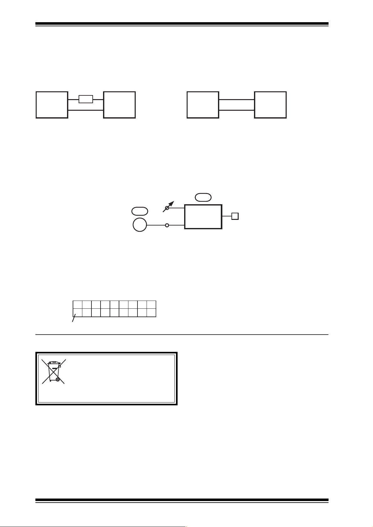
Connect the sensor’s heater supply.
(4) Connect the sensor to the IQ controller’s 24 V
auxiliary supply, or an external 12 V power
supply using the black and white leads as shown
below.
WS/R powered from IQ controller
Black
100R 24 Vdc
WS/R
White
5W
0 V
IQ Controller
auxiliary supply
WS/R powered from external 12 V supply
Black
WS/R
White
12 V
0 V
12 V External
supply
When powering the sensor’s heater from an IQ controller’s 24 V auxiliary supply it is necessary to connect a 100 Ω, 5 Ω resistor
in series with the sensor.
Note that if both the sensor’s power, and heater supply are from an IQ controller’s 24 V auxiliary supply, ensure that enough current
is available (125 mA approx.).
It is now necessary to configure the IQ controller to decode the signal from the sensor.
(5) Using a Trend configuration program configure
the controller to contain the strategy shown
below:
Sensor output:
0 V no rain
1 V rain present
K
V = 5 0
X
S
X + 1
F
E
D
F
C O M P
0 = No rain detected
1 = Rain detected
IQ Scaling
It is recommended to use SET (Software Tool) for the setting of sensor type modules. For all IQ2 series controllers with firmware
of version 2.1 or greater, or IQ3 series controllers the following SET Unique Sensor Reference should be used:
Rain Detector V
Alternatively select sensor type module scaling mode 5, (characterise) and enter scaling manually as defined in the table below.
For all other IQ controllers see the Sensor Scaling Reference Card, TB100521A.
YEULPI1I2O1O
04 00011-20010 0001
2
volts, V
DISPOSAL
WEEE Directive :
At the end of their useful life the packaging and
product should be disposed of by a suitable
Do not dispose of with normal household waste.
Do not burn.
Manufactured for and on behalf of the Environmental and Combustion Controls Division of Honeywell Technologies Sàrl, Ecublens, Route
du Bois 37,Switzerland by its Authorized Representative.
recycling centre.
Trend Control Systems Limited reserves the right to revise this publication from time to time and make changes to the content
hereof without obligation to notify any person of such revisions or changes.
Trend Control Systems Limited
P.O. Box 34, Horsham, West Sussex, RH12 2YF, UK. Tel:+44 (0)1403 211888 Fax:+44 (0)1403 241608 www.trend-controls.com
Trend Control Systems USA
6670 185th Avenue NE, Redmond, Washington 98052, USA. Tel: (425)897-3900, Fax: (425)869-8445 www.trend-controls.com
2
WS/R Rain Detector Installation Instructions TG102665 Issue 2/D 13/03/07
 Loading...