

Page 1
Wireless Plant Temperature Sensor
Important: Retain these instructions
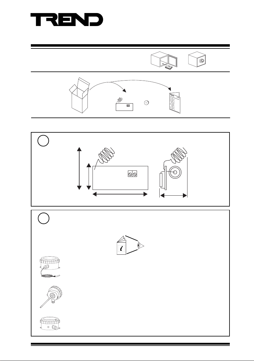
UNPACKING
INSTALLATION
Dimensions
1
40 mm (1.57”)
27 mm (1.06”)
Installation Instructions
TW/P
TW/P Installation
Instructions TG200782
63 mm (2.48”)
Requirements
2
Follow the requirements of plant sensor in which board is to be fitted.
a
TB/TC Installation Instructions TG200726
TE/TC Installation Instructions TG102385
TB/TI/S, TB/TI/L Installation Instructions TG200727
TE/TI Installation Instructions TG102386
TE/TD/S, TE/TD/L Installation Instructions TG102387
TB/TO Installation Instructions TG200725
TE/TO Installation Instructions TG102384
TW/P Wireless Plant Temperature Sensor Installation Instructions TG200782 Issue 2 10/07/08
45 mm (1.77”)
1
Page 2
TW/P Installation Instructions
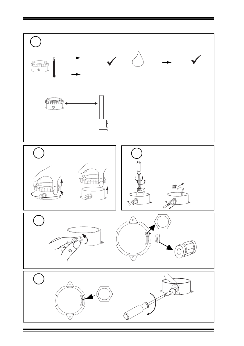
H O
2
INSTALLATION (continued)
Requirements (continued)
2
b
Note for ambient limits of probe see plant sensor installation instructions as in ‘a’ above.
c
Note that range may be affected
by environmental characteristics,
e.g. partitions, walls, building
structure etc.
ambient limits (box & electronics)
-10 °C
-14 °F
measurement range
-30 °C
-22 °F
+50 °C
+122 °F
+110 °C
+230 °F
75 m (82 yds)
(maximum)
XW/R/IQ
0 %RH
95 %RH
Protection IP20 (in box)
d
• Avoid using many other devices on
frequency range 433.05 to 434.79 MHz
• Keep away from sources of interference
(e.g. computer >1 m (1 yd), microwave
ovens, switch mode power supplies).
• Mount above partition height if possible.
Remove Lid
3
Unscrew M20 Gland
5
Screw in Blanking Plug
6
Remove terminal block
4
from lead
discard in an environmentally
friendly manner
See step 6
discard in an
environmentally friendly manner
2
TW/P Wireless Plant Temperature Sensor Installation Instructions TG200782 Issue 2 10/07/08
Page 3

Installation Instructions TW/P
000016746
00016746
INSTALLATION (continued)
Connect thermistor
7
Note Identification Number
8
000016746
00016746
Removeable identification label for installers own use
Fit board into mounting slots
9
00016746
000016746
‘location’
Replace Lid
10
TW/P Wireless Plant Temperature Sensor Installation Instructions TG200782 Issue 2 10/07/08
11
XW/R/IQ Installation Instructions TG200783
Install and Configure XW/
R/IQ Receiver
3
Page 4

TW/P Installation Instructions
INSTALLATION (continued)
12
TW/.., PCW/.., XW/R/IQ Data Sheet TA200780
13
e.g. TB/TI/..
Configure IQ
Test System
For IQ3 the sensor’s target analogue node must
be created using SET. An example strategy
including decoding of alarm bits is given in the
TW/.., PCW/.., XW/R/IQ Data Sheet
Check for alarm bits
BIT1 : Low Battery
BIT2 : Sensor fail
BIT3 : Loss of reception
see TW/.., PCW/.., XW/R/IQ Data Sheet, for
decoding of alarm bits.
XW/R/IQ
Δ T
IQ
2 min.
MAINTENANCE
The battery has a minimum life of 5 years. If the battery runs down the XW/R/IQ receiver will set an alarm
bit in the status data sent with the value. This corresponds to bit 1 (Low alarm). When the battery has run
down, the unit should be returned to the IQ system supplier for battery replacement.
DISPOSAL
WEEE Directive :
At the end of their useful life the packaging,
product, and batteries should be disposed
Do not dispose of with normal household waste.
Do not burn.
Please send any comments about this or any other Trend technical publication to techpubs@trendcontrols.com
© 2008 Honeywell Technologies Sàrl, ECC Divison. All rights reserved. Manufactured for and on behalf of the Environmental and Combustion Controls
Division of Honeywell Technologies Sàrl, Ecublens, Route du Bois 37, Switzerland by its Authorized Representative, Trend Control Systems Ltd.
Trend Control Systems Limited reserves the right to revise this publication from time to time and make changes to the content hereof
without obligation to notify any person of such revisions or changes.
Trend Control Systems Limited
P.O. Box 34, Horsham, West Sussex, RH12 2YF, UK. Tel:+44 (0)1403 21888 Fax:+44 (0)1403 241608 www.trend-controls.com
Trend Control Systems USA
6670 185th Avenue NE, Redmond, Washington 98052, USA. Tel: (425)897-3900, Fax: (425)869-8445 www.trend-controls.com
4
of by a suitable recycling centre.
TW/P Wireless Plant Temperature Sensor Installation Instructions TG200782 Issue 2 10/07/08
 Loading...