

Page 1
PRT Insertion Temperature Sensor
Important: Retain these instructions
UNPACKING
Installation
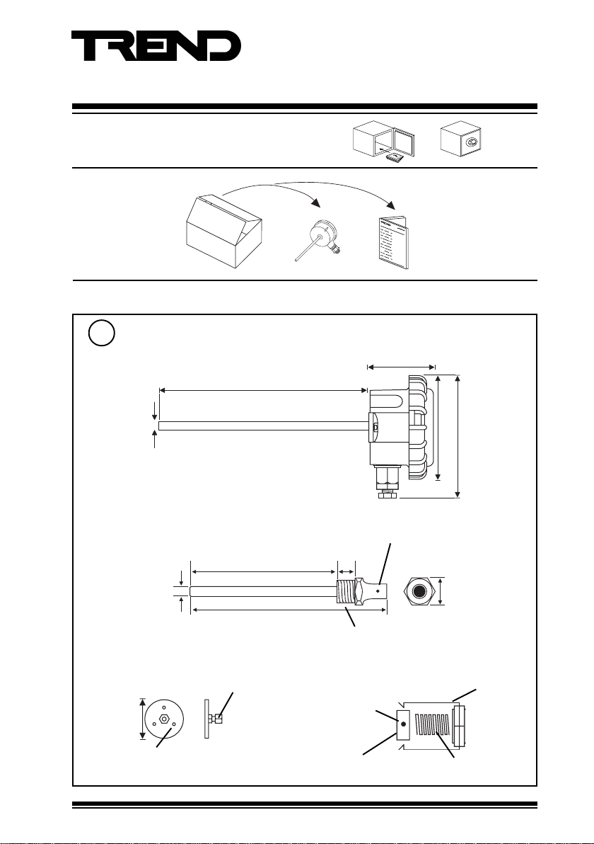
Dimensions
1
T/PI-L 400 mm (15.75”)
T/PI-S 150 mm (5.91”)
Installation Instructions
T/PI
T/PI Installation
Instructions TG200825
57 mm (2.24”)
6 mm (0.24”)
Pockets for use as immersion sensor
Brass (POC/B/6)
Stainless Steel (POC/SS/6)
106 mm (4.17”)
(0.37”)
9.5 mm
150 mm (5.91”)
Mounting flange for use as duct sensor Universal Fitting Kit for immersion sensor
ACC/DF/6
6 mm
compression
fitting
(1.97”)
50 mm
3 x 4 mm diam. holes
on a 30 mm (1.18”) PCD
T/PI PRT Insertion Temperature Sensor Installation Instructions TG200825 Issue 1/C 25/06/07
2 mm hexagonal socket
grub screw (each side)
17 mm (0.67”)
½” BSPT
use in existing pockets
hexagonal
socket grub
screw
brass bush
85 mm (3.35”)
27 mm (1.06”)
spring
105 mm (4.13”)
clip
1
Page 2
T/PI Installation Instructions
Installation (continued)
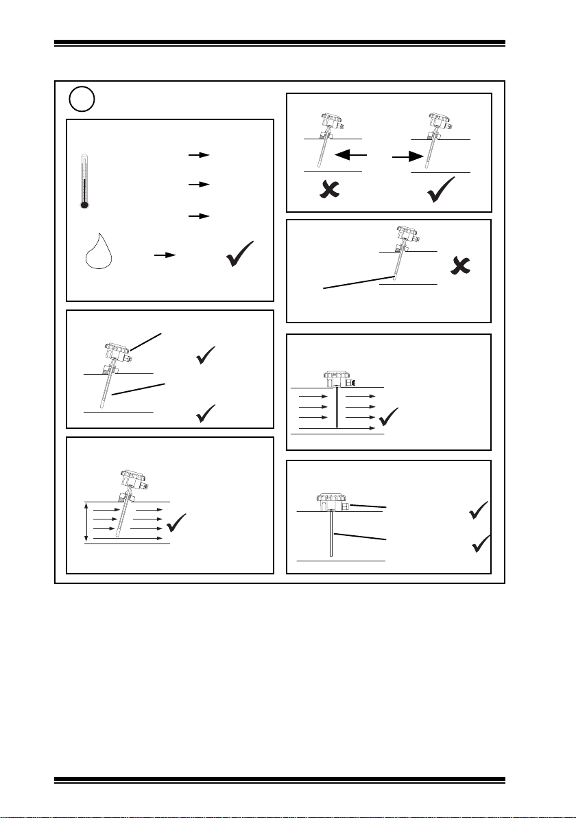
Requirements
2
Measurement range
a
/40 -10 °C (14 °F)
/110 -10 °C (14 °F)
/-40 -40 °C (-40 °F)
0 %RH 95 %RH
H O
2
Protection : IP67 (NEMA6)
Immersion
b
c
Immersion
+40 °C
(104 °F)
+110 °C
(230 °F)
+50 °C
(122 °F)
-40 °C
(-40 °F)
-40 °C
(-40 °F)
Ensure no stratification
(e.g. downstream of
mixing valves, junctions)
to
to
+50 °C
(+122 °F)
+110 °C
(+230 °F)
d
Immersion
Immersion
e
Cl
2
Note that POC/SS/6 or POC/B/6 are NOT
suitable for use in chlorine rich environments
Duct
f
Duct
g
Ensure no
stratification (e.g.
downstream of
mixing dampers,
heating coils,
cooling coils)
otherwise use
averaging sensor.
d
(minimum distance from junctions =10xd).
2
T/PI PRT Insertion Temperature Sensor Installation Instructions TG200825 Issue 1/C 25/06/07
-40 °C
(-40 °F)
-40 °C
(-40 °F)
+50 °C
to
(+122 °F)
+110 °C
to
(+230 °F)
Page 3
Installation Instructions T/PI
Installation (continued)
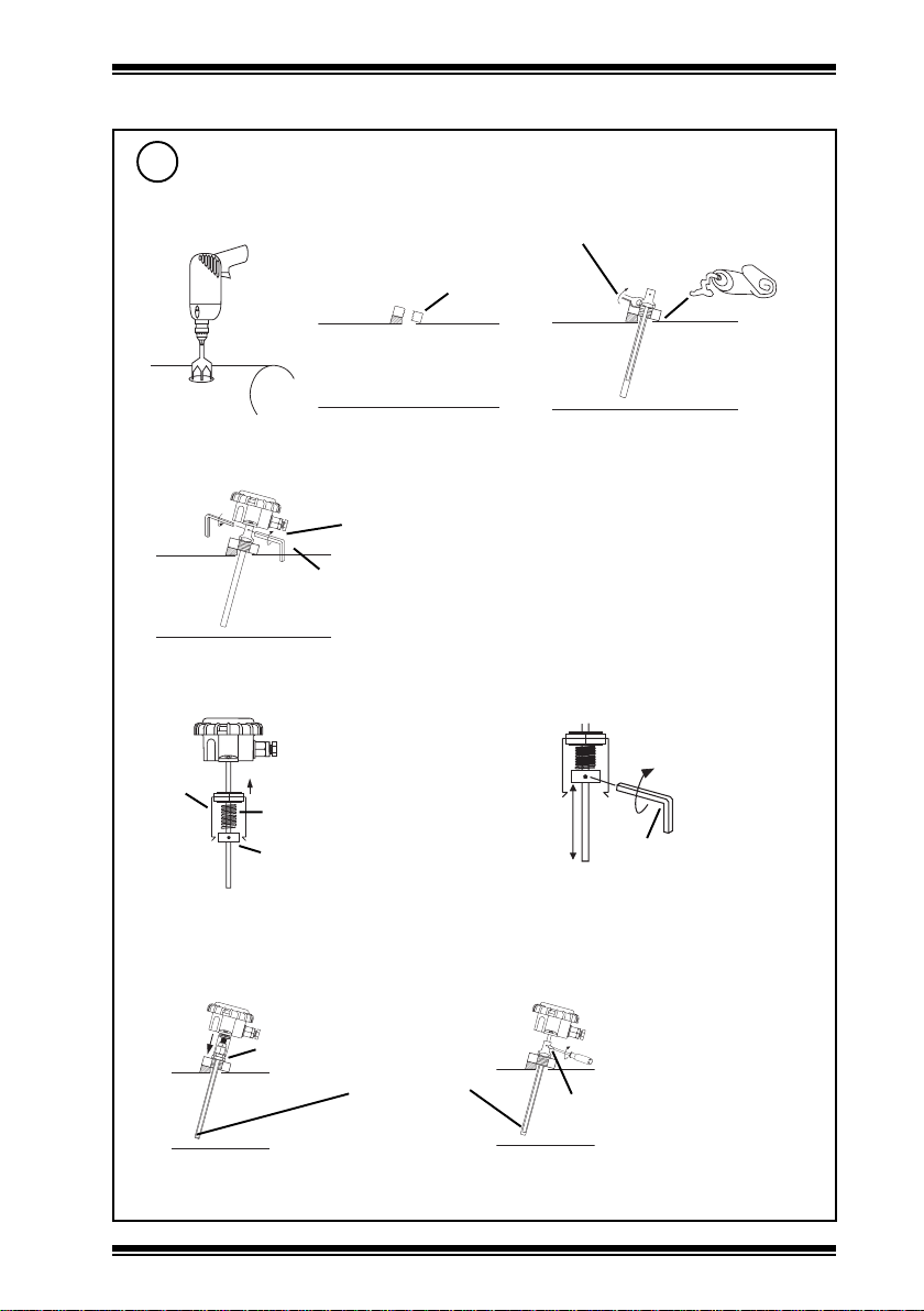
Install Immersion Sensor
3
Install Pocket
a
Drill hole for boss
a1
(if installing new pocket)
Fix threaded boss
a2
½” BSPT
threaded boss
*Screw pocket into boss
a3
use M27 Spanner
apply sealent to
boss thread
b Install Sensor into Pocket
tighten screws
use 2 mm hexagonal socket key
c Install Sensor into Pocket
Push adaptor onto probe
c1
clip
*Mount in pocket
c3
if pocket has clip retaining groove, push
clip over pocket
spring
brass brush
clip engages
in groove
probe is forced
against end of
pocket
If using compatible pocket
If using Universal Fixing Kit
Adjust probe length
c2
pocket
length
if pocket has grub screw, discard spring and clip
tighten screw
over bush
tighten
use 2 mm
hexagonal socket key
*If used for chilled water ensure pocket is sealed around probe or fill pocket with thermally
conducting oil to avoid the build up of condensation in bottom of pocket.
T/PI PRT Insertion Temperature Sensor Installation Instructions TG200825 Issue 1/C 25/06/07
3
Page 4

T/PI Installation Instructions
Installation (continued)
Install Duct Sensor
4
either
a Direct mount sensor on duct
a1
Drill hole in duct
Ø 7 mm
(0.28”)
Drill 2 pilot holes
a2
42.5 mm
(1.67”)
2 off
85 mm (3.35”)
or
b Use compression fitting
Separate compression fitting
b1
(1) Loosen nut
either
b2 (for thicker material) use compression fitting only
(1) tap hole
a3
(2) Unscrew fitting
(2) screw in fitting
3
2 off No 6
self tapping
screws
integral foam gasket
compression fitting
duct mounting flange
/4” s/s
drill and tap 1/8” BSPT
>6 mm
or
b3 (for thinner material) use
complete mounting flange
(1) drill 3 holes
3 off
pilot
holes
(2) screw on flange (3) mounted flange
3 off No 6 3/4” s/s self tapping screws
4
30 mm (1.18”)
<6 mm
T/PI PRT Insertion Temperature Sensor Installation Instructions TG200825 Issue 1/C 25/06/07
b4 Adjust depth of probe
either
or
Page 5

Installation Instructions T/PI
Installation (continued)
Remove Lid
5
Remove Connector
6
Insert Cable
7
either use M20 flexible conduit
Caution: This unit contains static
damage to the units. BS EN100015/
1 Basic Specification: protection of
electrostatic sensitive devices.
or use M16 cable gland
sensitive devices. Suitable
anti-static precautions
should be taken throughtout
the operation to prevent
Wire to Controller
8
Sensor
polarity independent
IQ system TP/I/22/HF/200
(Belden 8761) cable
recommended.
Terminal size 0.5 to 2.5 mm
(14 to 20 AWG)
Note that if connecting to an IQ22x controller (including /ADL or /OC), do not connect directly to
C (+24V), instead connect to AUX+ (+24V).
T/PI PRT Insertion Temperature Sensor Installation Instructions TG200825 Issue 1/C 25/06/07
2
Terminate screen at IQ end only
Sensor
IQ1xx, IQ2xx
24 Vdc
IN
IQ3
0 (0 V)
N (in)
+ (24 V)
Analogue input
channel linked
for current (I)
I
5
Page 6

T/PI Installation Instructions
Installation (continued)
Replace Connector
9
10
11
Replace Lid
Configure IQ
or
I Q
Note that IP67 (NEMA6) rating is only
achieved if the sensor is correctly installed
with cable or conduit connection fully
tightened.
I Q
IQ Configuration
Manual 90-1533
6
T/PI PRT Insertion Temperature Sensor Installation Instructions TG200825 Issue 1/C 25/06/07
Page 7

Installation Instructions T/PI
Installation (continued)
12
Set up IQ Sensor Type
It is recommended to use SET (Software Tool) for the setting of the sensor type module.
For all IQ2 series controllers with firmware version 2.1 or greater, or IQ3 series controllers,
the following SET Unique Sensor References should be used:
PRT I -10+40 (T/PI/40, °C)
PRT I +14+104 F (T/PI/40, °F)
PRT I -10+110 (T/PI/110, °C)
PRT I +14+230 F (T/PI/110, °F)
PRT I -40+50 (T/PI/-40, °C)
PRT I -40+122 F (T/PI/-40, °F)
Alternatively set scaling mode to 5 (characterise) and enter scaling manually as defined in
the appropriate table below. Note that for IQ3, the scaling mode and exponent do not need
to be set up.
For all other IQ controllers see Sensor Scaling Reference Card TB100521A
tinU04/011/04-/
epyttupni)tnerruc(2)tnerruc(2)tnerruc(2
tnenopxE 333
stinUC°F°C°F°C°F°
reppU0440101103205221
rewoL01-4101-4104-04-
stnioP 222222
xIxOxOxOxOxOxO
401-4101-4104-04-
020440101103205221
13
Test System
Y
E
U
L
P
x
1
2
IQ
T/PI PRT Insertion Temperature Sensor Installation Instructions TG200825 Issue 1/C 25/06/07
Δ T
7
Page 8

T/PI Installation Instructions
Disposal
WEEE Directive :
At the end of their useful life the packaging
and product should be disposed of by a
Do not dispose of with normal household waste.
Do not burn.
suitable recycling centre.
Manufactured for and on behalf of the Environmental and Combustion Controls Division of Honeywell Technologies Sàrl, Ecublens, Route
du Bois 37,Switzerland by its Authorized Representative, Trend Control Systems Limited.
Trend Control Systems Limited reserves the right to revise this publication from time to time and make changes to the content hereof
without obligation to notify any person of such revisions or changes.
Trend Control Systems Limited
P.O. Box 34, Horsham, West Sussex, RH12 2YF, UK. Tel:+44 (0)1403 21888 Fax:+44 (0)1403 241608 www.trend-controls.com
Trend Control Systems USA
6670 185th Avenue NE, Redmond, Washington 98052, USA. Tel: (425)897-3900, Fax: (425)869-8445 www.trend-controls.com
8
T/PI PRT Insertion Temperature Sensor Installation Instructions TG200825 Issue 1/C 25/06/07
 Loading...