

Page 1
Thermistor Room Temperature Sensors
Important: Retain these instructions
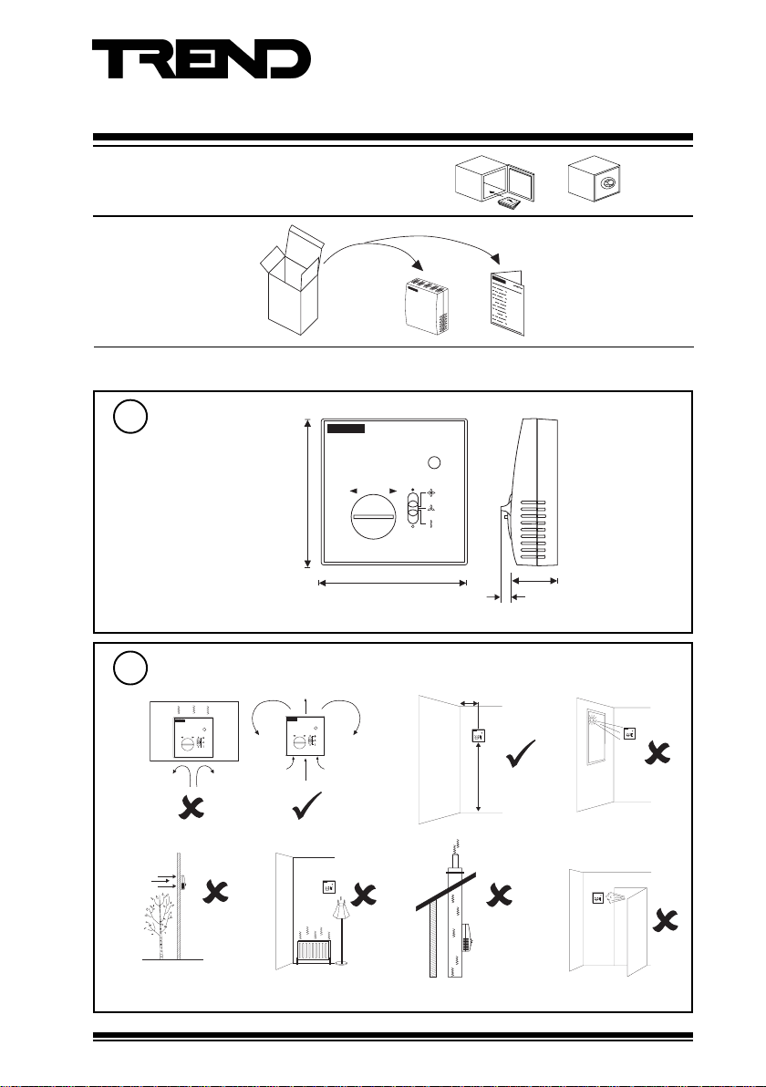
UNPACKING
Installation Instructions
TB/TS/KE, /KEF
TB/TS/KE, /KEF
Installation Instructions
TG200605
INSTALLATION
Dimensions
1
Requirements
2
a
d
e
For use with IQL controllers only
85 mm (3.35”)
85 mm (3.35”)
> 50 cm
b
f
26 mm (1.02”)
6 mm (0.24”)
c
1.5 m
g
TB/TS/KE, /KEF Sensors Installation Instructions TG200605 Issue 1/D 14/02/07
1
Page 2
TB/TS/KE, /KEF Installation Instructions
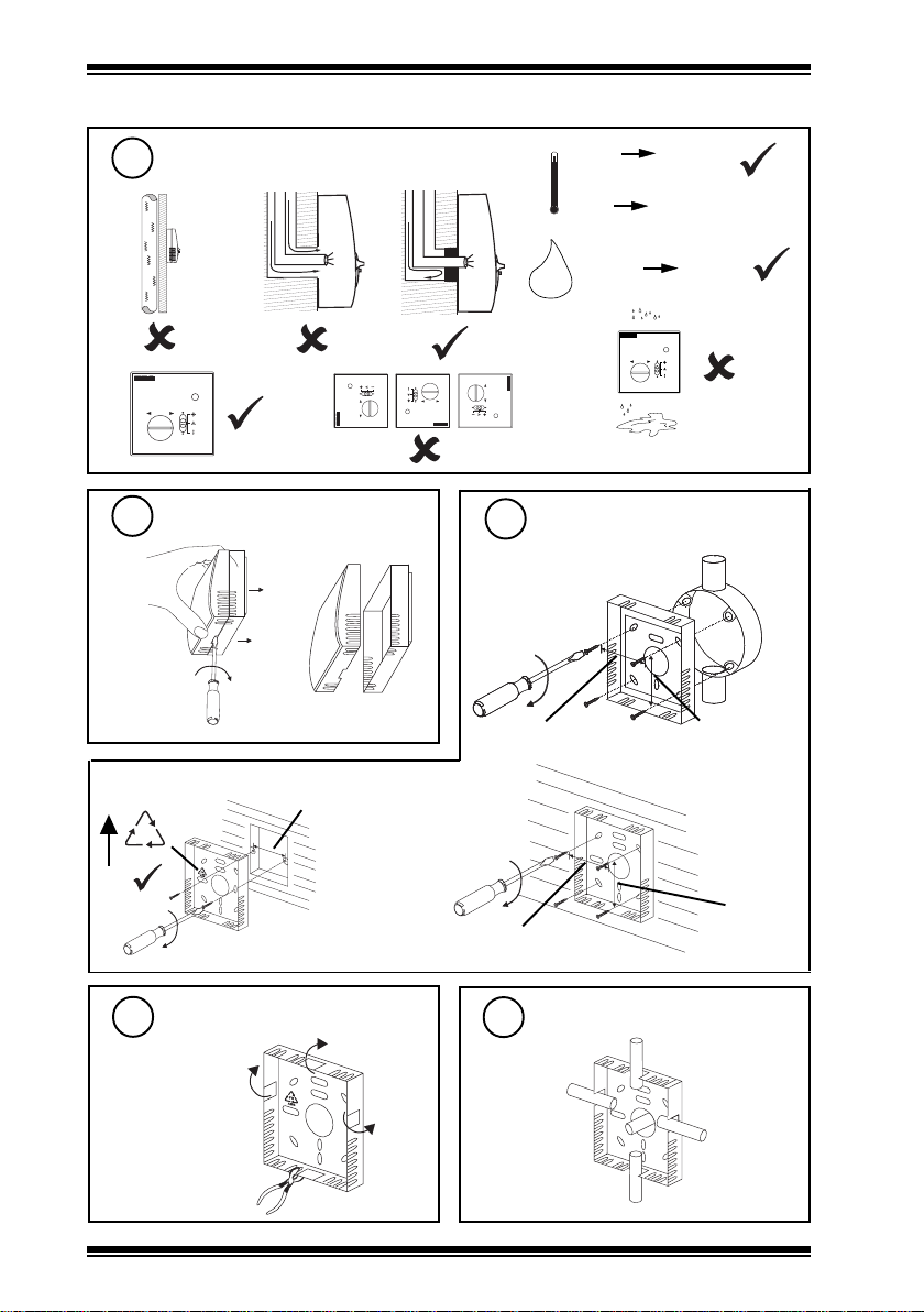
INSTALLATION (continued)
2
h
k
3
a
wall box
FR
ABS
Requirements (continued)
i
Remove backplate
b
60 mm (2.36”)
j
H O
2
l
Mount backplate
4
BESA box
35 mm (1.38”)
or wall
-10 °C
(14 °F)
0°C
(32 °F)
0 %RH
+50 °C
(122 °F)
+40 °C measurement
(104 °F)
90 %RH
35 mm (1.38”)
2
Remove cutout(s)
5
as required
35 mm (1.38”)
Route cables
6
TB/TS/KE, /KEF Sensors Installation Instructions TG200605 Issue 1/D 14/02/07
35 mm (1.38”)
Page 3

Installation Instructions TB/TS/KE, /KEF
1
3
2
1
2
3
54
TB/TS
/K
/E
C O M
1 5 1 6 1 7 1 8 1 9
1
2 3
C
I Q L 1 1 + / 2 3 0
INSTALLATION (continued)
Wire to controller
7
IQL only
LQISNOITPO
ST/BT
41,21,01LQI
71,+11LQI
+31LQI
+51LQI
61LQI
EK/ST/BT,K/ST/BT,ST/BT
FEK/ST/BT,EK/ST/BT,K/ST/BT,ST/BT
FEK/ST/BT,EK/ST/BT,K/ST/BT,ST/BT
K/ST/BT,ST/BT
Note that these options
1 2 3 4 5 6
(TB/TS/KE, or TB/TS/KEF) cannot
be used with IQs or FCs; use
options TB/TS, TB/TS/K, /KO, /
OS, /KOF, or /KOSF with IQs or
FCs.
I Q L 1 0 / 2 4 V A C
910
C O M
1 2
TB/TS
I Q L 1 2 , 1 4
1
C O M
2 1 2 2
2
1
TB/TS
I Q L 1 0 / 2 3 0
1
C O M
1 5 1 6
12
TB/TS
9 1 011 1 1 2
32154
/K
Terminal size 0.5 to 2.5 mm
(14 to 20 AWG)
Note that screened cable is not required
for sensor wiring to IQLs.
If screened cable is used, the screen
must be terminated at the controller to
its supply earth.
I Q L 1 6
1
2 3 4
C O M
C O M
2 1 2 2 2 3 2 4 2 5 2 6 2 7 2 8
5
C
I Q L 1 1 + / 2 4 V A C
1
C O M
1 3
C
/E
I Q L 1 7
2 3 4
A I
1 0 V
0 V
C O M
TB/TS
2
2 1 2 2 2 3 2 4 2 5 2 6 2 7 2 8
I Q L 1 3 + , 1 5 +
1
2 3 4
C O M
C O M
C
2 1 2 2 2 3 2 4 2 5 2 6 2 7 2 8
2
TB/TS
1
6
/F
54
/E
3
/K
5
C
5
TB/TS/KE, /KEF Sensors Installation Instructions TG200605 Issue 1/D 14/02/07
8
2
1
3
/K
TB/TS
Assemble unit
2
TB/TS
1
3
/K
54
/E
‘click’
3
Page 4

TB/TS/KE, /KEF Installation Instructions
INSTALLATION (continued)
Test system
9
IQL Installation Instructions
/E
I Q L
Δ T
Δ
/K
Δ SP
DISPOSAL
WEEE Directive :
At the end of their useful life the packaging
and product should be disposed of by a
Do not dispose of with normal household waste.
Do not burn.
suitable recycling centre.
/F
Manufactured for and on behalf of the Environmental and Combustion Controls Division of Honeywell Technologies Sàrl, Ecublens, Route
du Bois 37,Switzerland by its Authorized Representative.
Trend Control Systems Limited reserves the right to revise this publication from time to time and make changes to the content hereof
without obligation to notify any person of such revisions or changes.
Trend Control Systems Limited
P.O. Box 34, Horsham, West Sussex, RH12 2YF, UK. Tel:+44 (0)1403 21888 Fax:+44 (0)1403 241608 www.trend-controls.com
Trend Control Systems USA
6670 185th Avenue NE, Redmond, Washington 98052, USA. Tel: (425)897-3900, Fax: (425)869-8445 www.trend-controls.com
4
TB/TS/KE, /KEF Sensors Installation Instructions TG200605 Issue 1/D 14/02/07
 Loading...