

Page 1
Thermistor Outside Temperature Sensor
T B / T O
Tre nd C ontro l Sys tems
Hor sham , UK
T B / T O
Tre nd C ontro l Sys tems
Hor sham , UK
T B / T C
Tr end C on trol Sy ste ms
Ho rsh am , U K
T B / T C
Tr end C on trol Sy ste ms
Ho rsh am , U K
Important: Retain these instructions
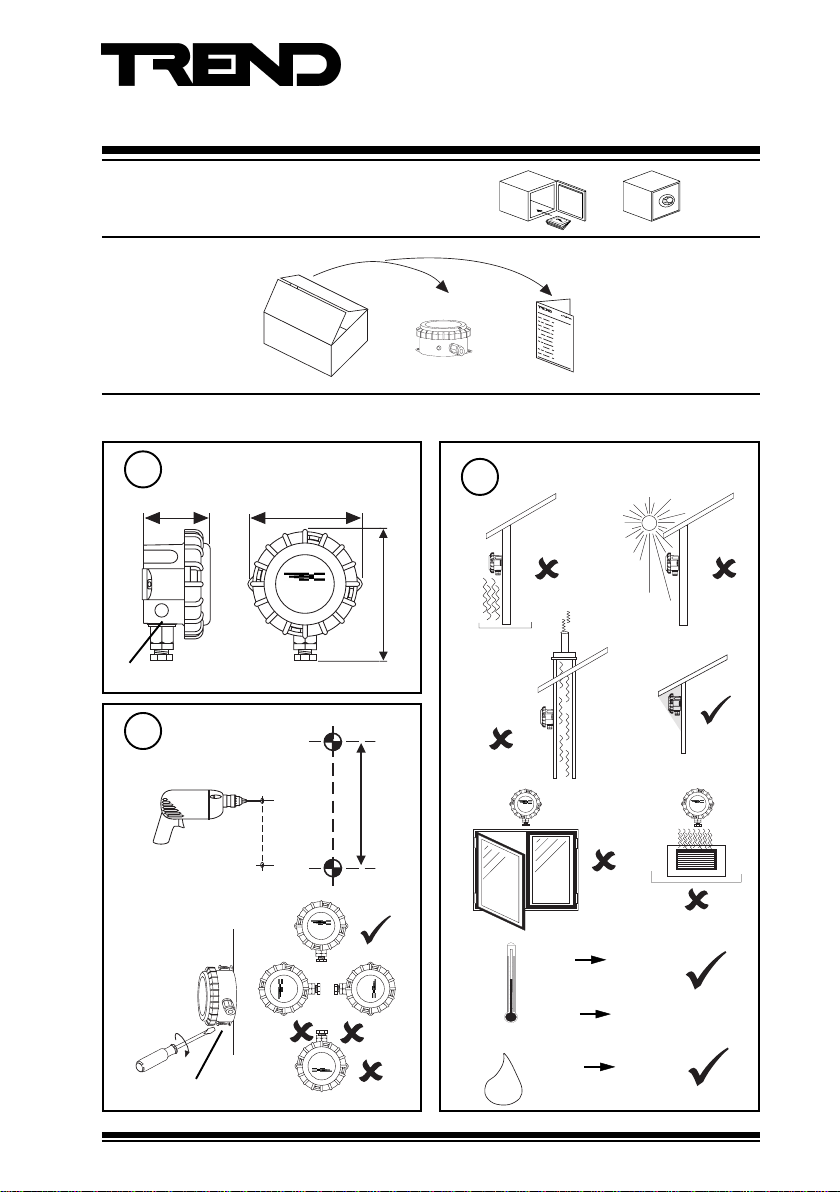
UNPACKING
Installation
Dimensions
1
57 mm (2.24”)
97 mm (3.82”)
T B / T O
T re n d C o n tr o l S y s t em s
H o rs h a m , U K
Installation Instructions
TB/TO
TB/TO Installation
Instructions TG200725
Requirements
2
ab
domed brass probe
Mount on Wall
3
drill 2 pilot holes
a
105 mm (4.13”)
c
d
ef
85 mm (3.35”)
tighten screws
b
2 off No 6 (M3.5) screws
TB/TO Thermistor Outside Temperature Sensor Installation Instructions TG200725 Issue 1/C 21/05/07
T B / T C
Tr end C ont rol Sy ste ms
Ho rsh am , U K
g
Ho rsh am , U K
Tr end C on trol Sy ste ms
T B / T C
ambient limits
-40 °C
(-40 °F)
measurement range
-30 °C
(-22 °F)
0 %RH
H O
Protection :IP67
2
+50 °C
(+122 °F)
+50 °C
(+122 °F)
95 %RH
1
Page 2
TB/TO Installation Instructions
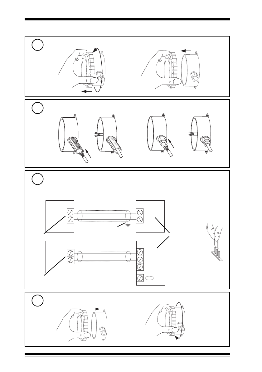
Installation (continued)
4
a
5
either use
M20 flexible
conduit
6
polarity
independent
polarity
independent
Remove Lid
Insert Cable
b
or M16 cable gland
Wire to Controller
terminal size 0.5 to 2.5 mm2 (14 to 20 AWG)
TP/1/1/22/HP/200 (Belden 8761) cable recommended
Sensor
terminate screen at
IQ end only
Sensor
IQ1xx/2xx
COM (0V)
IN
IQ3
0 (0V)
N (in)
+ (24 V)
Analogue input
channel linked for
thermistor (T)
T
7
Replace Lid
b
a
2
TB/TO Thermistor Outside Temperature Sensor Installation Instructions TG200725 Issue 1/C 21/05/07
Page 3

Installation Instructions TB/TO
Installation (continued)
Configure IQ
8
or
I Q
I Q
IQ Configuration Manual
90-1533
Set up IQ Sensor Type
9
It is recommended to use SET (software tool) for the setting of the sensor type module. For all
IQ2 series controllers with firmware version 2.1 or greater, or IQ3 series controllers, the following
SET Unique Sensor Reference should be used:
Thermistor: Thermistor TBTO (°C)
Thermistor TBTO F (°F)
Alternatively set scaling mode to 5 (characterise), and enter scaling manually as defined in the
appropriate table below.
For all other IQ controllers see Sensor Scaling Reference Card TB100521A.
Thermistor (-30 °C to +50 °C, -22 °F to +122 °F)
:stinUC°F°
1
01
11
epyttupnI
tnenopxE
reppU
rewoL
stnioP
146.205221
074.304401
064.40368
366.60105
866.7023
201.85-32
284.801-41
708.851-5
870.902-4-
992.952-31-
674.903-22
Y
E
U
L
P
xxIxO
2
3
4
5
6
7
8
9
or Thermistor (-10 °C to +40 °C, 14 °F to +104 °F)
)Vmreht(1
3
55131
53-13-
11
-
:stinUC°F°
1
epyttupnI
tnenopxE
reppU
54311
rewoL
51-5-
stnioP
074.304401
064.40368
366.60105
866.7023
201.85-32
284.801-41
Y
E
U
L
P
xxIxO
2
3
4
5
6
)Vmreht(1
3
6
10
Test System
T B / T O
Tr en d Co nt ro l S ys tem s
H ors ha m , U K
IQ
Δ T
TB/TO Thermistor Outside Temperature Sensor Installation Instructions TG200725 Issue 1/C 21/05/07
3
Page 4

TB/TO Installation Instructions
Disposal
WEEE Directive :
At the end of their useful life the packaging
and product should be disposed of by a
Do not dispose of with normal household waste.
Do not burn.
suitable recycling centre.
Manufactured for and on behalf of the Environmental and Combustion Controls Division of Honeywell Technologies Sàrl, Ecublens, Route
du Bois 37,Switzerland by its Authorized Representative, Trend Control Systems Limited.
Trend Control Systems Limited reserves the right to revise this publication from time to time and make changes to the content hereof
without obligation to notify any person of such revisions or changes.
Trend Control Systems Limited
P.O. Box 34, Horsham, West Sussex, RH12 2YF, UK. Tel:+44 (0)1403 21888 Fax:+44 (0)1403 241608 www.trend-controls.com
Trend Control Systems USA
6670 185th Avenue NE, Redmond, Washington 98052, USA. Tel: (425)897-3900, Fax: (425)869-8445 www.trend-controls.com
4
TB/TO Thermistor Outside Temperature Sensor Installation Instructions TG200725 Issue 1/C 21/05/07
 Loading...