

TREND TB-TC User Manual
Thermistor Contact Temperature Sensor
Important: Retain these instructions
UNPACKING
Installation
Installation Instructions
TB/TC
TB/TC Installation
Instructions TG200726
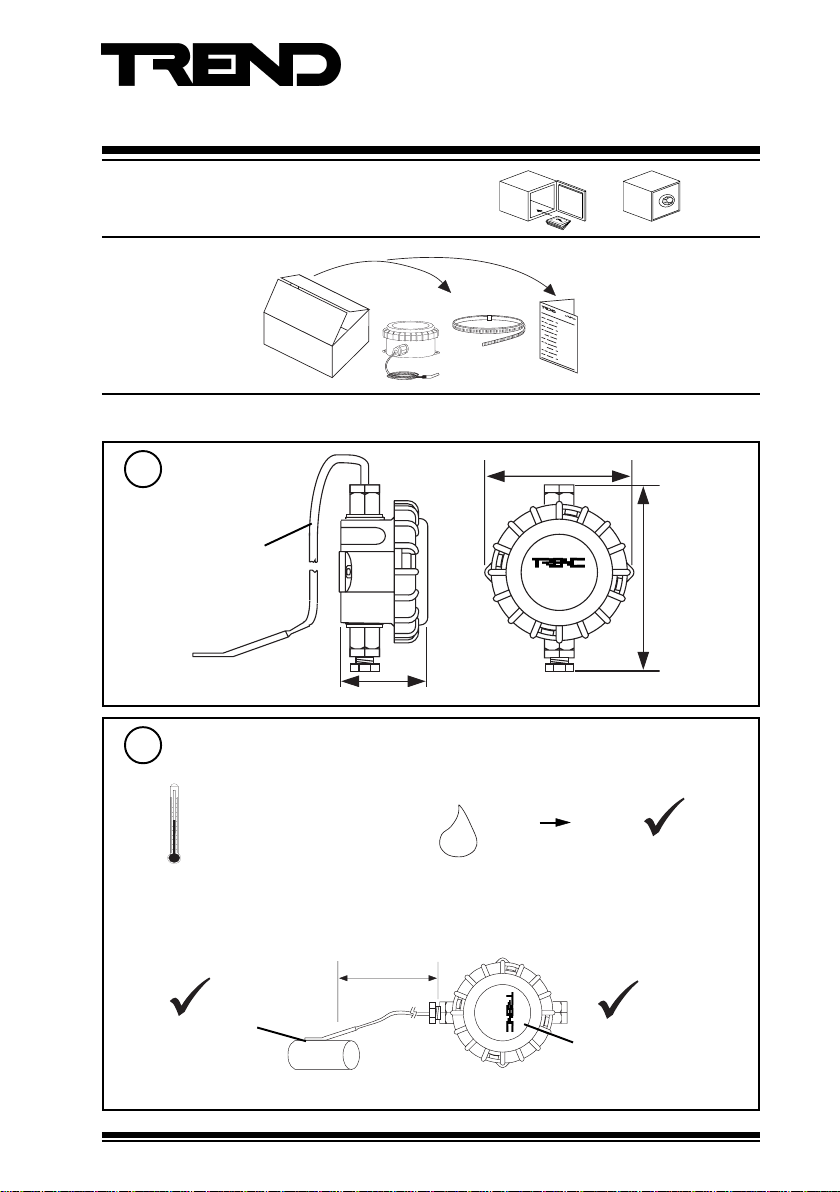
Dimensions
1
2 m (6’6”) cable
Requirements
2
a
b
-40 °C to +100 °C
(-40 °F to +212 °F)
measurement range
-30 °C
(-22 °F)
to
+100 °C
(+212 °F)
57 mm (2.24”)
2 m (6’6”) max
97 mm (3.82”)
T B / T C
0 %RH 95 %RH
H O
2
Protection :IP67
T B / T C
T re n d Co n tr ol S ys te m s
H o rs ha m , U K
T r en d C o n tr o l S y s te m s
H o r sh a m , U K
-40 °C to +50 °C
(-40 °F to +122 °F)
114 mm (4.61”)
TB/TC Thermistor Contact Temperature Sensor Installation Instructions TG200726 Issue 1/C 21/05/07
1
TB/TC Installation Instructions
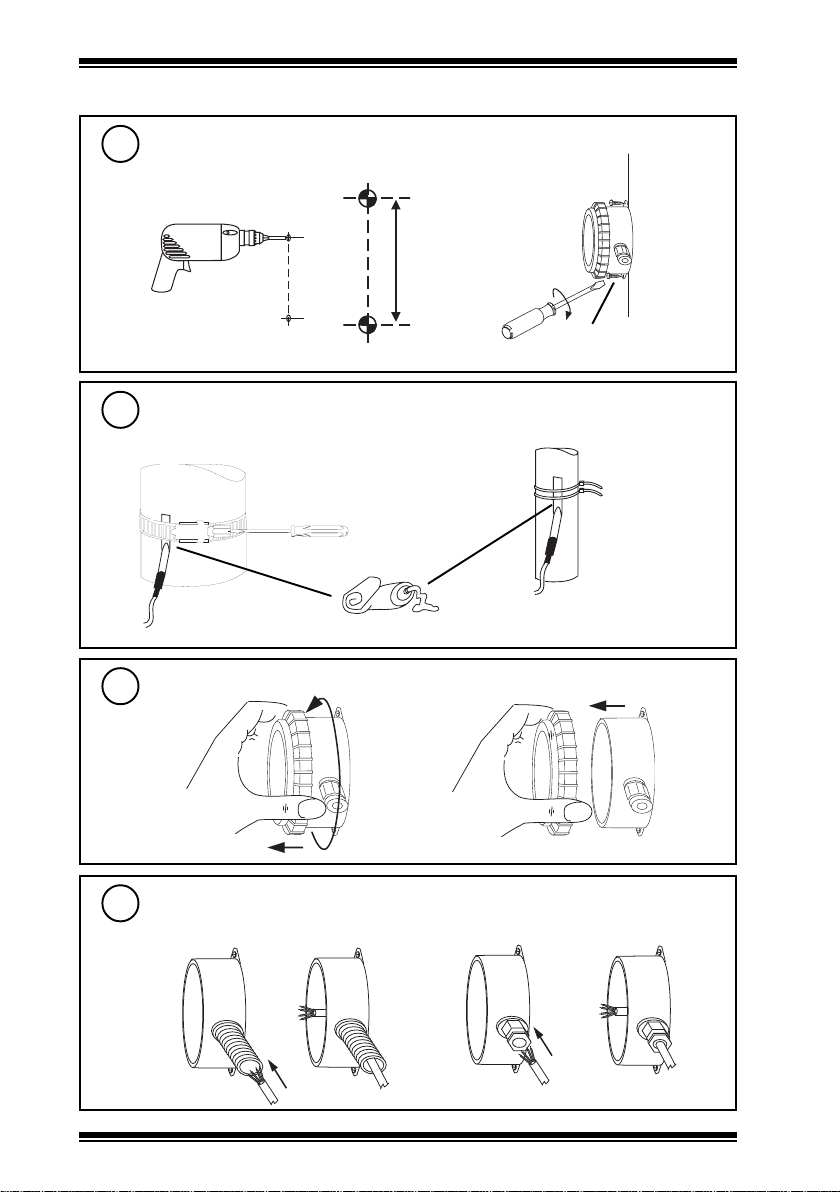
Installation (continued)
Mount on Wall
3
Drill 2 pilot holes
ab
85 mm (3.35”)
Tighten 2 screws
2 off No 6 (M3.5) screws
Mount Probe
4
either use jubilee clip (provided)
recommended use of thermally conductive paste
Remove Lid
5
a
Insert Cable
6
either use M20 flexible conduit
or use cable tie(s) (not provided)
b
or M16 cable gland
2
TB/TC Thermistor Contact Temperature Sensor Installation Instructions TG200726 Issue 1/C 21/05/07
 Loading...