

Page 1
ELECTRONIC/PNEUMATIC-TRANSDUCER
APPLICATION
An E/P Transducer accepts a proportional voltage signal
from an electronic controller and converts it into a proportional pneumatic signal of 0.2 to 1.0 bar to operate
pneumatic actuators or reset pneumatic controllers.
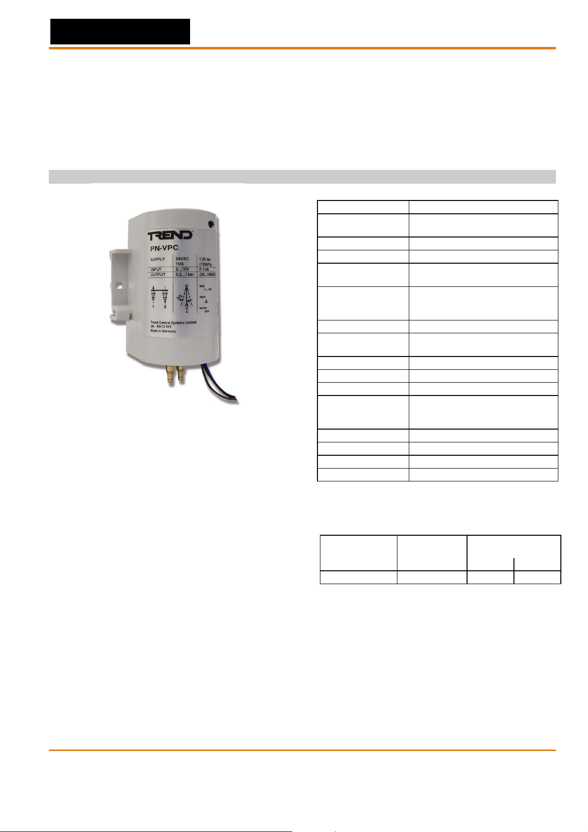
The PN-VPC accepts a 2...10 Vdc / 4...20 mA signal. It
includes a voltage to current converter. The PN-VPC
requires an external 24 Vac power supply.
MAINTENANCE
A full range of maintenance programs is available from your
local registered Trend office.
PN-VPC
PRODUCT DATA
SPECIFICATIONS
Type No. PN-VPC
Power supply
Power consumption 1.7 VA
Input signal 2... 10 V
Min. current at
10 Vdc
0.02 bar (2 kPa) max. at 0 Vdc Output pressure at
1.25 bar (125 kPa)
main pressure
Main air pressure 1.25 bar (125 kPa)
Main air pressure
independence
Maximum safe air 2.0 bar (200 kPa)
Air consumption 42 NL/h (700 sccm) at 0.6 bar
Air capacity 720 NL/h (12000 sccm)
Air connections
Calibration Factory calibrated
Ambient temperature 5...55ºC
Storage -30...+70ºC
Humidity 5...95% RH
All E/P-Transducers supplied with 1 m cable
1.12 bar (112 kPa) min. at 11.5 Vdc
1% per 0.1 bar main air pressure
Dual-barb-fittings for either 6 x
1 mm (1/4“ O.D.) or 4 x 0.75 mm
(5/32“ O.D.) polyethylene tubing.
WIRING
Distance
E/P-Transducer
to ... 100 m 150 m
Controller local standard 1.0 mm21.5 mm
See also
NOTE: The E/P Transducer connection wire 24 V ⊥
Fig. 3.
(black) must be connected to the same potential
0 V level as the controller.
Type of wire length max.
+10% / -15%
24 V, 50/60Hz
(0.1 mA)
2
PN-VPC Data Sheet TA200855 Issue 1/B 28/03/07 1
EN0B-0505GE51 R0307B
Page 2

PN-VPC Data Sheet
OPERATION
The input signal 2...10 V is fed into a voltage to current
converter in the PN-VPC.
The current through the coil produces a magnetic force on
the flapper. This force is balanced by the feedback force
developed by the nozzles pressure on the opposite side of
the flapper.
When the magnetic force on the flapper changes due to a
change in current, the position of the flapper over the
nozzle changes, and a new pressure is established. This
pressure is used to pilot the pneumatic amplifier, which
converts the low capacity pilot pressure to a high capacity
branch line. The operation span is fixed and the startpoint
of the output signal is factory calibrated.
Both transducers are compensated to eliminate ambient
temperature influence. The transducers are protected by a
rigid plastic cover.
38
diameter
4.1
4.5
5°
7
47
51.5
62
Fig. 1. PN-VPC dimensions (in mm)
MOUNTING
Wall mounting with two screws 4 mm diameter (see Fig. 1).
Rail mounting using the European Standard Rail 35 x 7.5
(EN 50022) (see
Mount the transducer in the vertical position ONLY with a
maximum of 5 angular degree tolerance to the
perpendicular line (see
Fig. 2).
Fig. 1).
78
13.5
1. For test or indication gauge
2. Additional length to dismount from rail
Fig. 2. Mounting
START-UP INSTRUCTIONS
Before starting up the system, the following checks should
be made on the transducer:
1. Check that main line pressure is available and input
voltage is at maximum i.e. 12 Vdc.
2. Check that output pressure is at minimum i.e 120 kPa
(1.2 bar).
3a. If the output pressure is within the transducer rating, the
system can be started up.
3b. If not, short out the contact pins with a screwdriver.
When this is done, the sound of discharging air should be
heard.
4. Check for correct output pressure build-up and repeat
step 3(b) if transducer does not function correctly.
BLUE
PN-VPC
c
o
n
v
e
r
t
e
r
BROWN
BLACK
Y = 2...10 Vdc
24 V~
24 V
Fig. 3. Wiring and connections
DISPOSAL
WEEE Directive
At the end of their useful life the packaging
and product should be disposed of by a suitable
recycling centre.
Do not dispose of with normal household waste.
Do not burn.
:
Manufactured for and on behalf of the Environmental and Combustion Controls Division of Honeywell Technologies Sàrl, Ecublens, Route du Bois 37,Switzerland by its Authorized Representative.
Trend Control Systems Ltd reserves the right to revise this publication from time to time and make changes to the content hereof without obligation to
notify any person of such revisions or changes.
Trend Control Systems Limited
P.O. Box 34 Horsham, West Sussex, RH12 2YF, UK. Tel: +44 (0)1403 211888, Fax: +44 (0)1403 241608, www.trend-controls.com
2 PN-VPC Data Sheet TA200855 Issue 1/B 28/03/07
EN0B-0505GE51 R0307B
 Loading...