

Page 1
Installation Instructions
NXNI Trend NX Variable Speed Drive Network Interface
Important: Retain these instructions
NXNI
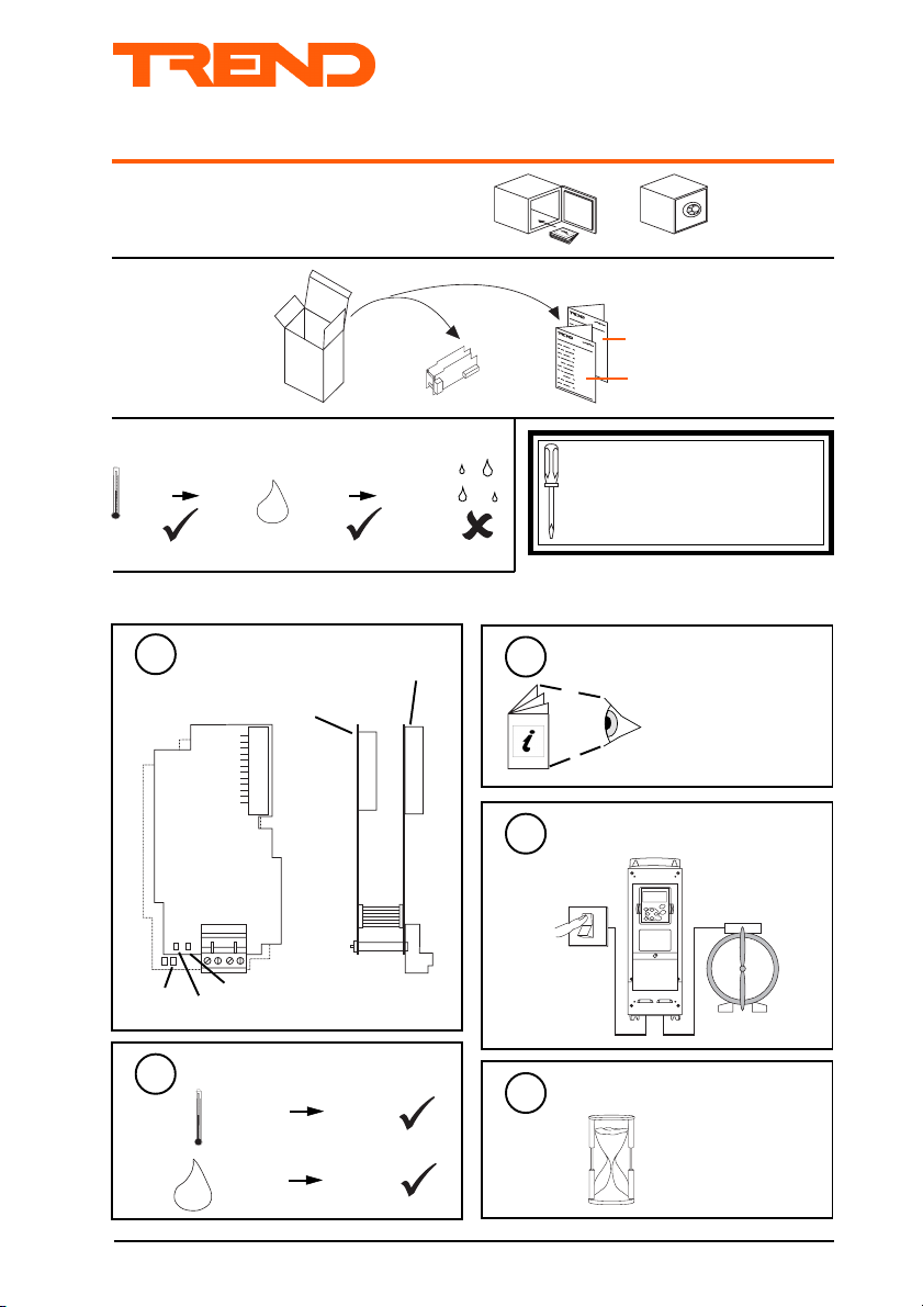
UNPACKING
STORING
-40 °C
INSTALLATION
OK LED
+70 °C
Physical
1
NX Drive
Communication Board
L E D 1
L E D 2
RX LED
TX LED
H O
0 %RH
2
95 %RH
Trend Lan Board
NXNI Installation Instructions
TG200543
Sheet 1
Sheet 2
1
It is recommended that the installation
should comply with the HSE
Memorandum of Guidance on
Electricity at Work Regulations 1989.
Install NX drive
3
NX Drive Installation
Instructions TG200434
Switch off Supply
4
O
I
Requirements
2
-10 °C
0 %RH 90 %RH
H O
2
NXNI Trend NX Variable Speed Drive Network Interface Installation Instructions TG200543 Issue 1/A 15/5/02
+50 °C
5
Wait 5 minutes
5 minutes
1-1
Page 2
NXNI Installation Instructions
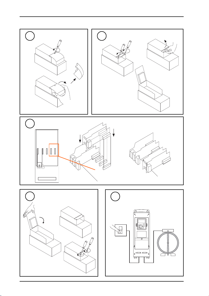
INSTALLATION (continued)
Remove Cover
6
a
b
Plug NXNI into NX Drive
8
A B C D E
7
a
B C D E
Open Lid
b
c
Close Lid
9
b
a
c
NXNI Trend NX Variable Speed Drive Network Interface Installation Instructions TG200543 Issue 1/A 15/5/02
1-2
10
Switch on Power to NX Drive
O
I
Page 3
Installation Instructions NXNI
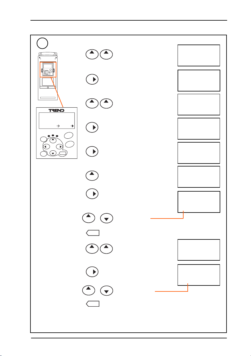
INSTALLATION (continued)
Set Address/Baud Rate
11
+
M1 → M7 (Expander boards)
+
M7
Expander boards
G1 → G5
M L
M O N I T O R
r e s e t
s e l e c t
V 1 V 1 3
+
-
e n t e r
S T A R T
G7.1
A : NXOPTA1
G1 → G2
G7.4
G7.1
+
G7.1 → G7.4 (Board Slot D)
+
D : NXOPTC2
G1 → G2
G7.4.1
G7.4.1 (Parameters)
Parameters
P1 → P6
S T O P
G7.4.1.1 (Comm Protocol)
G7.4.1.1
Comm Protocol
MODBUS RTU
G7.4.1.2
+
G7.4.1.2 (Slave Address)
Edit Mode
Slave Address
1
G7.4.1.2
Slave Address
‘1’
-
+
or
e n t e r
Change Address
(Valid range 4 to 9, 12 to 119)
Confirm change
P7.4.1.3 Baud
+
P7.4.1.3 Baud
+
Baud Rate
9600 Baud
Edit Mode
P7.4.1.3 Baud
Baud Rate
‘9600 Baud’
-
or
+
e n t e r
Note that other paramteters should not be changed:
Change Baud Rate
(Valid baud rates: 1200, 4800, 9600, 19200)
Confirm change
Comm Protocol : MODBUS RTU
Parity Type : Node
Comm Time-out : 10s
Operate Mode : Normal
NXNI Trend NX Variable Speed Drive Network Interface Installation Instructions TG200543 Issue 1/A 15/5/02
1-3
Page 4

NXNI Installation Instructions
T
T
R
R
X
T
T
R
R
T -
T + R -
R +
INSTALLATION (continued)
Change Parameters from Keypad
12
if required
uneMretemaraPegnahCotnosaeR
)lortnoCdapyeK(3M)ecalPlortnoC(1.3PO/I:lortnocfoecruosseifitnedisihT
:noitacilppAdradnatSrof.g.e
)retemarap(2M11.1.2P
.noitceles
21.1.2P
ycneuqerfdapyeK
.noitcelesecnerefer
31.1.2P
ycneuqerfsubdleiF
.noitcelesecnerefer
13
Connect Network
Terminal size 0.5 to 2.5 mm2 (14 to 20 AWG)
elbaCduab2k1duab8k4duab6k9duab2k91seriWfo.oN
2819nedleBm0001m0001m0001m0072
7029nedleBm0001m0001m0001m0052
dnerT
dnerT
m0001m0001m007m0532
005/FH/22/1/1/PT
)1678nedleB(
m0001m0001m005m0524
005/FH/22/2/2/PT
)3278nedleB(
polarity independent
2 wire
TRTRTRT
R
LAN
ecnereferycneuqerfO/I
.evoba
dapyeK=2
4 wire
T R T R T R T R
NX Drive Installation
Manual TG200434
Application Manual
TE200443
.)INXN.e.i(subdleiFro,dapyeK,slanimret
nactubslanimretO/IeblliwsihtyllamroN
lortnocotsiINXNfi,INXNotdegnahceb
.)tirotinomtsujton(tinueht
)launaMnoitacilppAees(sretemaraplanoitiddaseificepsevirdXNehtnigninnurnoitacilppaehT
ecnereferycneuqerffoecruossetatciD
salortnocniteseraslanimretO/Inehw
)top.g.e(3,2slanimretO/I=0
5,4slanimretO/I=1
)INXN(subdleiF=3
.lortnocnisidapyeKnehwtubevobasA
.lortnocnisisubdleiFnehwtubevobasA
Network Engineering
Manual 92-1735
LAN
T -
R +
R
R
T + R -
T
T
X
additional terminals
14
Configure/Commission
NXNI Installation Instruction,
TG200543 - Sheet 2
1-4
NXNI Trend NX Variable Speed Drive Network Interface Installation Instructions TG200543 Issue 1/A 15/5/02
Page 5

Installation Instructions
O
I
NXNI Trend NX Variable Speed Drive Network Interface
INSTALLATION (continued)
Fix unit
1
2
Check Network
a
NXNI Installation Instruction,
TG200543 - Sheet 1
LED2
RX
(yellow)
2
I Q
?
NXNI
LAN
T X - T X + R X - R X +
OK
IQ Faulty
LAN
T X - T X + R X - R X +
LED1
b
TX
(yellow)
c
Lan OK
(green)
I Q
I Q
?
OK
Check network cabling
for short circuits with a
multimeter (NOT
Megger)
Check baud rate
Switch on other nodes
unitl fault node is found
(OK
). Correct fault.
.
NXNI Trend NX Variable Speed Drive Network Interface Installation Instructions TG200543 Issue 1/A 15/5/02
2-1
Page 6
NXNI Installation Instructions
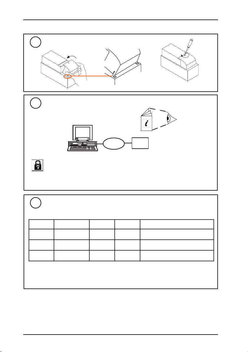
INSTALLATION (continued)
Replace Cover
3
Connect Trend tool for Text Communications
4
if required
Wupdn
PowerTool
+
Terse Text
Communications
Note that a PIN may be required to make changes. If the PIN has been forgotten the users
should contact their supplier (installers contact Trend Technical Support) quoting the
generator number and serial number (both from Address module) whereupon a default PIN
will be supplied. This will only work for three attempts at entering the PIN. After the default PIN is
entered a new PIN should be set up and remembered.
Lan
NXNI
PowerTool Manual
TE200163
Wupdn Manual
TE200162
Set up Control Parameters
5
if required (using text comms (Supervisor) or IC Comms (IQ))
metInoitpircseDstinUegnaRgninaeM
1KdnameD%001-0
1WlangiSdnammoC1/0
2WteseRtluaF1/0
Note: K1, W1, W2 will only control NX drive if P3.1 (Control Place) is set to Fieldbus.
Note: In standard strategy K1 will only work if P3.1 (Control Place) is set to Fieldbus and P2.1.13
(Fieldbus frequency reference Select) is set to 3 Fieldbus, or P2.1.11 and P2.1.12 are set to 3
appropriate to other Control Places.
NXNI Trend NX Variable Speed Drive Network Interface Installation Instructions TG200543 Issue 1/A 15/5/02
2-2
.0otkcabhctiws
deepsrotommumixamdna
)rotoMnuR(nO=1
)rotoMpotS(ffO=2
muminimneewtebegnarfo%001ot0
teS.tluafraelcot1othctiwsteS
Page 7

Installation Instructions NXNI
INSTALLATION (continued)
Set up Other Parameters
6
if required (using text comms (Supervisor) or IC Comms (IQ))
eludoMretemraPtluafeDegnaRnosaeR
sserddA
NnaLlacolnwO0 911ot11,9ot4,1smmoCCIroF
R
DreifitnedIecafretnINXNsretcarahc61edonyfitnedioT
F2etubirttAecafretnINXNsretcarahc61
G3etubirttAecafretnINXNsretcarahc61
AsserddAmralA0 911ot11,9ot4,1
RnaLmralA0 911ot11,9ot4,1
emiT
HsruoH- 32ot0
T
NsetuniM- 95ot0
D)etaD(yaD- 13ot1
MhtnoM- 21ot1
Y)stigidowt(raeY- 99ot0
resU
PrebmunniP0 9999ot0
U
LleveL0 99ot0
rosneS
HlevelmralahgiH0
02Sot1S
LlevelmralawoL0
DyaledmralahgiH0
AyaledmralawoL0
NstibelbanemralA0000000011000000ot00000000
bonK
TstimilpoT001
1K
BstimilmottoB0
tupnI
EmralAelbanE01ot0
01Iot1I
tolP
SrebmunrosneS- 02ot1
3Pot1P
PlavretnignittolPm51
To change display and directory modules see NXNI Data Sheet
ces1tpecxeegnardradnats
,m1=3,h42=2,m51=1,h1=0(
,m02=6,m01=5,m5=4
)h6=8,m03=7
rofderiuqerfI
etubirtta
gnisserdda
rofderiuqerfI
etubirtta
gnisserdda
enifedesehT
tegratmrala
htobdnasserdda
ottesebtsum
smraladnes
tesebtsumemiT
pmatsemitotpu
dnasmrala
gniggol
tcetorpoT
foytiruces
retemarap
segnahc
rosnesrofputeS
woldnahgih
owttsaL.smrala
stibelbane
hgih/wolelbane
smrala
ylevitcepser
egnaregnahcoT
bonkfo
tupnielbaneoT
mrala
rosnesegnahC
dettolpgnieb
gnittolpegnahC
lavretni
NXNI Trend NX Variable Speed Drive Network Interface Installation Instructions TG200543 Issue 1/A 15/5/02
2-3
Page 8
NXNI Installation Instructions
N X N I
I Q
L a n
K 1
W 1
S 1
W 2
I 1
I 1 0
S 2 0
N X
N X
N X
N X
INSTALLATION (continued)
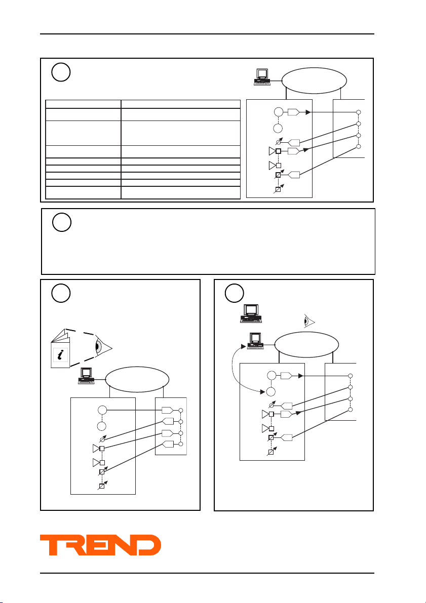
Set up IC Comms for NXNI
7
Use PowerTool or Wupdn (see step 3) and terset text
communications IC Comms Module Nx(.. - (x=1 to 6)
if required
retemaraPnoitcnuF
sserddaecivedetomeR-A
etubirttA-B
naLetomeR-N
lavretnI-I)setunim(gnidnesneewteblavretnI
egnahctnacifingiS-S gnidneserofebegnahctsumeugolanatnuomA
gnirtsmetiecruoS-M ))V(1S.g.e(tnesgniebretemarapdnametI
epytnoitanitseD-T
)'3etubirtta'3,'2
labolglabolgseificeps
rebmuneludomnoitanitseD-E smmocCIgniviecereludomnoitanitsedfo.oN
seificepsorez-nonfI.smmoc'otlabolg',orezfI
smmoc'otatad'rofsserddaecivedtegrat
,QItegratfoetubirtta,ylnosmmoc'otlabolg'roF
on'0(eludomsserddanietubirttasecnerefer
etubirtta'2,'reifitnedi'1,naLnosQIlla-,'etubirtta
,orezsserdda,oreznaLfi;rebmunnaLQItegraT
.)K,W,I,S(smmocgniviecereludomntsedfoepyT
edoneugolanaotsdnes)tluafed(gnirtsllunfI
Write any changes to Flash memory
8
if any strategy parameters have been changed
If any changes to strategy parameters have been made, a text comms reset command R(z=1)
should be sent to the NXNI to commit changes to the flash memory and render them non-volatile
to power interruptions. This should be done once after all changes are made.
Note that the command R(z=1) should be used with caution to preserve memory life
Set up IC Comms from IQ
9
IC Comms ‘direction’ in IQ must be: Global To,
Min, Max, Sum, or Average (directions 2 to 6).
Trend Control Systems Ltd reserves the right to revise this publication from time to time and make changes to the content hereof
without obligation to notify any person of such revisions or changes.
Trend Control Systems Ltd P.O. Box 34 Horsham Sussex RH12 2YF Tel:+44 (0)1403 211888 Fax:+44 (0)1403 241608 www.trend-controls.com
2-4
if required
T e r s e T e x t
see IQ Configuration
C o m m s
Manual 90-1533
L a n
N X N I
S 1
S 2 0
K 1
I 1
I 1 0
W 1
W 2
NXNI Trend NX Variable Speed Drive Network Interface Installation Instructions TG200543 Issue 1/A 15/5/02
I Q
N X
N X
N X
N X
Note that any changes to the strategy parameters
should be followed by a text comms reset
command, R(z=1) after all changes are made, to
commit changes to flash memory and render
them non-volatile to power interruptions.
- Use with caution to preserve memory life
Set up Text Comms from
10
Supervisor if required
terse text comms
e.g. S1(V)
L a n
N X N I
S 1
N X
S 2 0
K 1
N X
I 1
N X
I 1 0
N X
W 1
W 2
I C C o m m s
I Q
 Loading...