

Page 1
NXL Variable Speed Drives
Data Sheet
NXL
Variable Speed Drives
Description
Variable motor speed drives suitable for a wide range of voltage
and current loads. Convert fixed frequency and voltage from the
mains supply to variable frequency and voltage enabling motors to
be used with maximum efficiency resulting in significant energy
savings. The drive has a built-in PID control application that can be
adjusted from the control keypad.
NXL drives are suitable for mounting in a small space, using back,
side, or DIN rail mounting.
The drives are easily programmed and commissioned by using
the control keypad or PC tools software.
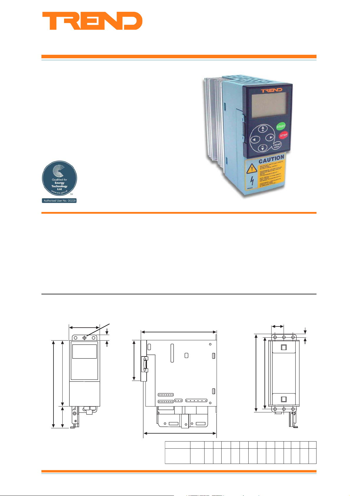
Physical
(dimensions in mm)
Microdrives
H4
H1
W2
Ø
H7
H5
Features
• 380 to 500 Vac 3 phase or 208 to 240Vac single phase supply
• current rating range from 1.9 A to 61 A (0.37 kW to 30 kW)
• built-in multi-control application
• multilingual control panel
• integrated RFI filter for industry strength EMC
• versatile PC tools available
• slim, space-saving, “bookshelf” design
• additional I/O, 3 digital inputs, 2 digital outputs (Ecodrives only)
D1
H2
W1
H3
H8
H6
D2
epyTemarF1W2W1H2H3H4H5H6H7H8H1D2DØ
NXL Variable Speed Drives Data Sheet TA200620 Issue 1/G 13/06/07
&,51000LXN
&,52000LXN
2FM03062712510410310824116 0514416
1C2000LXN
1
Page 2
NX L Data Sheet
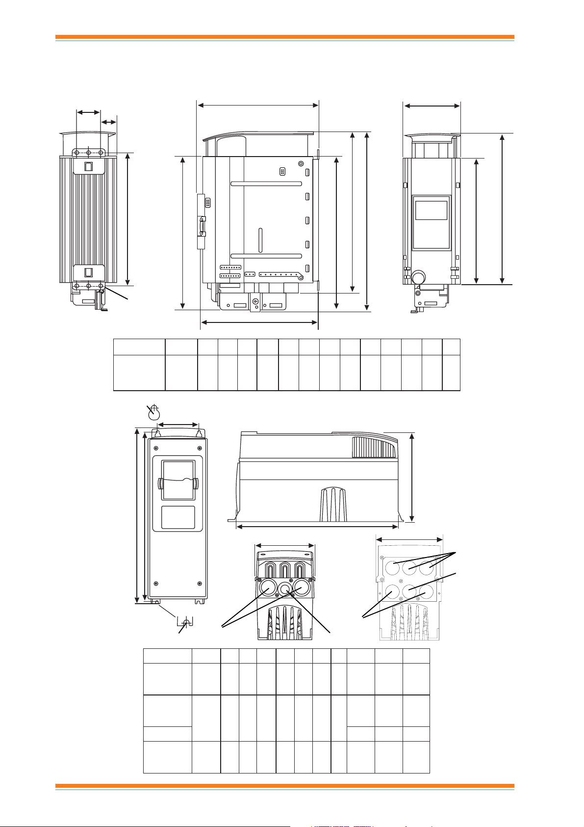
Physical
(dimensions in mm)
Microdrives
W2
W3
D1 W1
Ecodrives
H5
H3
Ø
D2
H2
H1
H4
epyTemarF1W2W3W1H2H3H4H5H6H7H1D2DØ
1C3000LXN
ot
3FM4853322625323229913914810222716616
1C6000LXN
Ø
W2
D1
H7
H6
H1
H2
IP21
Ø
P
W1
H3
IP54
P
B
epyTemarF1W2W1H2H3H1DØ P B C
xx30AALXN
ot
4FM8210017233132920917 02x202x152x1
W1
C
B
P= power cable
B= brake cable
C= control cable
xx21AALXN
xx61AALXN
ot
5FM4410019146041934127
xx32AALXN
52x252x152
x1
xx13AALXN23x252x152x1
xx83AALXN
ot
6FM5918418551459157329 23x223x152x1
xx16AALXN
2
NXL Variable Speed Drives Data Sheet TA200620 Issue 1/G 13/06/07
Page 3
Data Sheet NXL
21 22 23
9 10 11 18 19
A B
1 2 3 4 5 6 7 8
L1 L2 L3
U/T1
V/T2
W/T3
BR+
BR-
30
1~
FUNCTIONALITY
The NXL range of variable speed drives provides both three phase to three phase (1 A to 61 A) and single phase to three phase
(2 A to 6A) units. Of particular use in the HVAC environment, they enable fans and motors to regulate delivery of air and water
in variable flow applications. Where flow rates may be reduced, motor energy can be significantly cut as the relationship between
flow rate and power follows a cube law hence reducing flow by 20% reduces power by 50%. The drives also enable saving in
installation costs; switchgear is eliminated, motor cables are reduced from 6 to 3 wires, power factor correction capacitors are
not required, size and cost of cabling and fuses is minimised (as starting current is kept within nominal value).
The sensorless flux vector control gives dynamic precision over most of the speed range. A drive is provided with built-in control
application, which can be set up from the control keypad. It has a slot for an optional I/O expansion board.
HARDWARE
The Trend NXL is an extremely slim, space-saving and
easy-to-use frequency converter for the power range of 0.37
to 30 kW. The installation is flexible and easy using the mounting
components shipped with the unit. Traditional back installation
and side installation, suitable for very limited space, are available,
as well as DIN rail mounting.
An optimal solution is available for most application needs. The
modular design allows the choice of only the functions and
features needed in a specific application. The control keypad is
fitted as standard. The NXOPTAA board (3 x digital inputs, 1 x
digital relay output, and 1 x digital open collector output) is fitted
as standard in the I/O expansion slot of the Ecodrives; it can be
fitted as an optional extra in the Microdrives. At the core of the
Easy programming and commissioning add to overall
user-friendliness. The default control I/O of the Trend NXL includes
the most common control inputs and outputs. For maximum
compatibility, the connector numbers correspond to those of the
Trend NX drives. Parameter setting is carried out in a familiar
NXL is sensorless vector control technology coupled with current
measurements of all three output phases. Fieldbus control using
RS485 Modbus is available as standard. The Trend NXL also
incorporates PID control as standard, enhanced with a host of
special features such as a sleep function.
way, either via the control panel or by means of the PC tools for
the NXL.
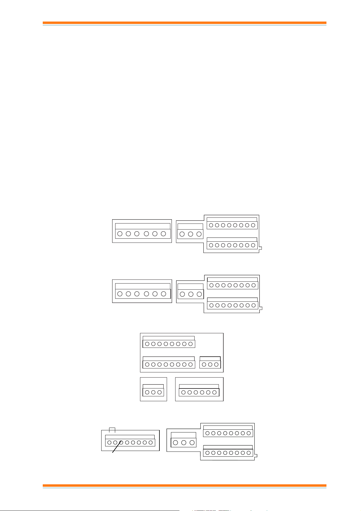
Terminals for NXL0002C1 (MF2 single phase to three phase)
L1 L2 L3 U/T1
V/T2
W/T3
21 22 23
Terminals for NXL00015, NXL00025 (MF2 three phase to three phase)
L1 L2 L3 U/T1
V/T2
W/T3
21 22 23
910111819A B
12 3 4 5 6 7 8
910111819A B
30
30
Terminals for NXLAA03xx to NXLAA61xx where xx = C2 or C5 (MF4 to MF6)
910111819A B
123456783021 22 23
L1 L2 L3
B- B+ R-
Terminals for NXL0003C1 to NXL0006C1 (MF3 single phase to three phase)
not used
NXL Variable Speed Drives Data Sheet TA200620 Issue 1/G 13/06/07
12 3 4 5 6 7 8
U/T1 V/T2 W/T3
3
Page 4
NX L Data Sheet
HARDWARE (continued)
Standard I/O The unit provides basic I/O connections
directly to suit common applications for NXL.
Typical connector for Multicontrol Application
1
2
3
4
5
6
7
8
9
10
11
mA
18
19
A
B
30
21
22
23
I/O Board NXOPTAA Additional control inputs and
outputs are provided by the NXOPTAA I/O board (3 x
digital inputs, 1 x digital relay output, and 1 x digital
open collector output). It is fitted as standard to the
Ecodrives and can be fitted as an optional extra to the
Microdrives.
Terminals for I/O card NXOPTAA
123 456
24 25 26
slanimretlortnoctuptuOdnatupnILXN
lanimreTlangiStnemmoC
1ferV01+egatlovecnerefeRAm01tnerrucmumixaM
2ro+1IA
4NID
3-1IA/DNGnommoctupnieugolanA;dnuorgotdetcennoctonfitupnilaitnereffiD
4+2IAtnerruc,tupnieugolanA)mho052=iR(Am02ot0
5-2IA/DNGnommoctupnieugolanA;dnuorgotdetcenno
6tuoV42egatlovyrailixuaV42Am001tnerrucmumix
7DNGdnuorgO/IslortnocdnaecnereferrofdnuorG
81NID1tupnilatigiD).nim(mhok5=iR
92NID2tupnilatigiD
013NID3tupni
11DNGdnuorgO/IslortnocdnaecnereferrofdnuorG
81+1OA)tuptuo+(langiseugolanALR,Am02ot)4(0tnerruC:egnarla
91-1OAnommoctuptuoeugolanA
A584SRsublaireSrotsisernoitanimreT
B584
SRsublaireSrotsisernoitanimreT
121/1ORCN1tuptuoyaleRcdV521,caV052egatlovgnihctiwsmumixaM
222/1ORMOC1tuptuoyaleR
323/1ORON1tuptuoyaleR
03V42+egatlovtupnixuAV42pukcabylppusrewoplortnoC
lanimreTretemaraPtnemmoC
3X
1V42+ ,ctesehctiwsrofegatlov;tuptuoegatl
2DNG ODdnaV42+rofg.e,slortnocrofdnuorG
31NID1.x:NIGID1tupnilatigiD
42NID2.x:NIGID2tupnilatigi
53NID3.x:NIGID3tupnilatigiD
61OD1.x:TUOIDV84/Am05,tuptuorotcellocnepO
5X
42CN/1OR2.x:TUOID1tuptuoyaleR
52C/1OR
62ON/1OR
tnerruc
latigiD
roegatlov,tupnieugolanA
ademmargorpebnac
nereffidV02±swollA
am,%01±
ngistuptuO
hctiwsmumixaM
dnuorgO/Iehtmorf
slanimretstuptuOdnatupnIrednapxEAATPOXN
ovlortnoC
Am051.xam
D
A4.0/cdV521
iR(Am02ot0ro)mhok002=iR(cdV01ot0
4NIDs
ctonfitupnilaitnereffiD
cdV521/A4.0,caV052/A8
Am01/V5daolgnihctiws.niM
,A8/cdV42yticapacgnihctiwS
4Xkcolbrepmujhtiwnoitceles)mho052=
DNGotegatlovedomlait
DNGotegatlovedomlaitnereffidV02±swollA
mhok1>LR,V01ot0egatloVromho005xam
,cdV42/A8tnerrucgni
detalosiyllacinavlageraslanimrettuptuoyaleR
,A8/caV052
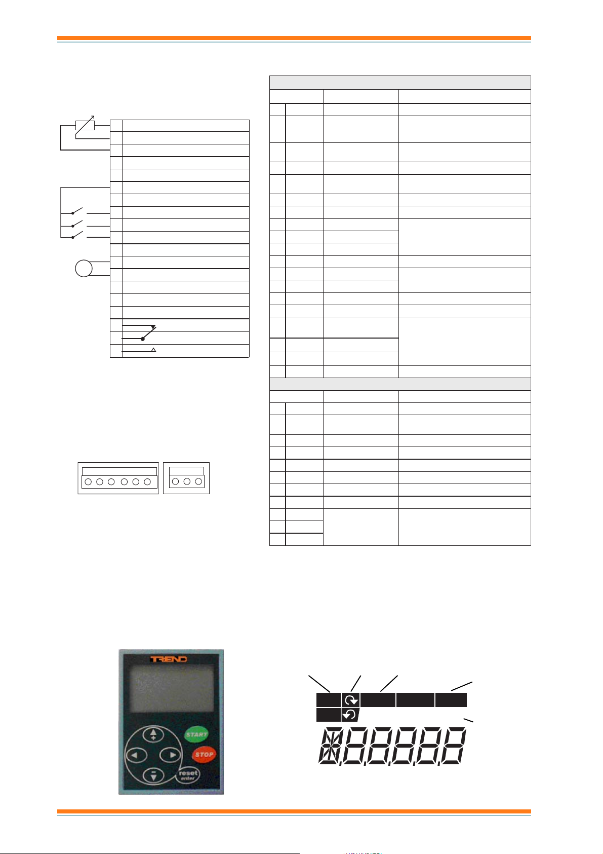
Control Keypad: The control keypad is used for parameter
setting, reading status data, and giving control commands. It is
detachable and can be operated externally being connected via
a cable to the frequency converter. A PC can be connected and
used to control the frequency converter instead of the control
keypad. (A 1.5 m, 9 way D type male to female extension cable
is available, ACC/NXL/RS232PC. A door mounting kit including a
2m cable is available, NXLDRA.)
4
The Trend NXL control keypad features a seven-segment display
with seven indicators for the Run status (RUN, READY, STOP,
ALARM, FAULT) and three indicators for the control place
(I/O term/ Keypad/BusComm). The control information, i.e. the
number of menu, the displayed value and the numeric information
are presented with numeric symbols.
The frequency converter is operable through the seven
push-buttons of the control keypad. Furthermore, the buttons
serve the purposes of parameter setting and value monitoring.
run status drive stopped
rotation power on, not tripped
due to fault
RUN
STOP
READY ALARM FAULT
I/O term Keypad Bus/Comm
control signal
value
mA V s % kHz °C °F rpm kWh
NXL Variable Speed Drives Data Sheet TA200620 Issue 1/G 13/06/07
Page 5

Data Sheet NXL
HARDWARE (continued)
The keypad has seven buttons which are used for controlling
the drive, setting parameters, and monitoring values.
nottuBesU
teserstluafevitcasteser
retne)sces3ot2rofdloh(yrotsihtluafteserronoitcelesmrifnoc
+puseulavtide,un
empuesworb
-nwodseulavtide,unemnwodesworb
tfeltidetixe,tfel,unemnidrawkcabevom
thgirtideretne,thgir,unemnid
rawrofevom
tratsecruoslortnocsidapyekfirotomstrats
potsecruoslortnocsidapyekfirotomspots
The Keypad can be made the control source at any time by pressing
the left arrow button for 5 secs. The keypad may then be used to
start and stop the motor and to ramp its speed up and down by
increasing or decreasing the output frequency shown on the
display using the up and down keys. Pressing the left hand arrow
button again for 5 secs will return the drive to remote control.
Note that the motor is stopped as the control changes from
remote to local and vice versa.
The main menu consists of individual items M1 to E7 which are
browsed using up and down buttons, the submenus under these
menus are then browsed by left/right buttons.
M1 Monitoring: This enables the following signals to be
monitored only.
edoCemaNlangiSstinUnoitpircseD
1.1VycneuqerftuptuOzHrotomehtotycneuqerF
2.1VecnereferycneuqerFzH
3.1VdeepsrotoMmprd
4.1VtnerrucrotoMAtnerrucrotomderusaeM
5.1VeuqrotrotoM% tinuehtfoeuqrotlanimon/euqrotdetalu
6.1VrewoprotoM% tinuehtforewoplanimon/rewopdetaluclaC
7.1VegatlovrotoMVegatlovrotomdetaluclaC
il-CDVegatlovknil-CDderusaeM
8.1Vegatlovkn
9.1VerutarepmettinUC°erutarepmetknistaeH
01.1V1tupnieugolana/egatloVV1IA
11.1V2tupni
21.1VtnerructuptuoeugolanAAm1OA
31.1V
41.1V
51.1V3NID,2NID,1NIDsesutatstupnilatigiD
61.1V3EID,2EID,1EID sesutatstupnil
71.1V1ORsutats1tuptuoyaleR
81.1V3EOR,2EOR,1EOR sesutatstuptuoyaleR:draob.pxeO/I
V1EOD sutats1tuptuolatigiD:draob.pxeO/I
91.1
02.1VecnereferDIP% ecnereferssecorpmumixamehtfotnecrepnI
12.1Veulavlau
22.1VeulavrorreDIP% eulavrorremumixamehtfotnecrepnI
32.1VtuptuoDIP% eulav
42.1V3,2,1stuptuoegnahcotuAlortnocnafdnapmupniylnodesU
eugolana/tnerruCAm2IA
,1tnerructuptuoeugolanA
draobrednapxe
ructuptuoeugolanA
,2tner
draobrednapxe
tcaDIP% eulavlautcamumixamehtfotnecrepnI
claC
Am
Am
eepsrotomdetaluclaC
atigiD:draobrednapxeO/I
tuptuomumixamehtfotnecrepnI
P2 Parameters: This enables the parameters to be edited. First
the group of parameters is selected, then the individual
parameter. The parameters below are for the basic group (P2.1),
other groups are used and are described in the NXL Application
Manual :
edoCretemaraPtluafeDetoN
1.1.2Pycneuqerf.niMzH00.0
2.1.2Pycneuqerf.xaMzH00.05
3.1.2PemitnoitareleccAs0.1
4.1.2Pemit
5.1.2PtimiltnerruCAlanimoNx5.1
6.1.2PegatlovrotomlanimoNV004
7.1.2PycneuqerfrotomlanimoNzH00.
8.1.2PdeepsrotomlanimoNmpr0441
9.1.2PtnerrucrotomlanimoN
01.1.2PihpsocrotoM58.0
11.1.2PnoitcnuftratS0
21.1.2PnoitcnufpotS0
31.1.2Pnoitasim
41.1.2PecnereferO/I0
51.1.2Pegnarlangis
61.2PnoitcnuftuptuoeugolanA1
71.1.2Pnoitcnuf2NID1
81.1.2Pnoitcnuf3NID6
1.1.2P1deepsteserPzH00.01
9
02.1.2P2deepsteserPzH00.05
12.1.2PtratsercitamotuA0
22.1.2Plaecnocrete
noitarelecceDs0.1
05
itpof/U0
1IA=0
2IA=1
2IA2
qerF=2
)deeps
)euqrot
)rewop
1
xE=3
desU=1
maraP1
pmaR=0
atsgniylF=1
tr
gnitsaoC=1
pmaR=1
desuton=0
dapyeK=2
subdleiF=3
desuton=0
)tnerrucrotom
rotoM=5
)egatlovrotom
nil-CD=8
desuton=0
luppotS=3
elbanenuR=6
PelbasiD=9
)ecnerefer
1kcolretnI=01
desuton=0
esreveR=1
tesertluaF=4
elbanenuR=5
rotoM=01
)ecnerefer
2kcolretnI=31
desutoN=0
tsaocelbanenuR+pmaR=2
pmarelbanenuR+tsaoC=3
tsoobeuqrotcitamotuA=1
Am02otAm0=1
Am02otAm4=2
)xamfot0(.qerftuptuO=1
)xamfot0(ecnerefer.
lanimonot0(tnerructuptuO=4
lanimonot0(egatlovrotoM=7
)V0001ot0(tlovk
eulavferrellortnocIP=9
eulavlautcarellortnocIP=01
eulavrorrerellortnocIP=11
tuptuorellortnooIP=2
esreveRtratS=1
)drawroftratS=1NID(
)tratS=1NID(esreveR=2
cc,tluaflanretxE=4
co,tluaflanretxE=5
2deepsteserP=7
cc,tluaflanretxE=2
co,tluaflanret
1deepsteserP=6
2deepsteserP=7
)esluptratS=1NID(es
)cc(PU.toprotoM=8
.qerftceriD(DI
dnammocgnikarb-CD=8
)cc(PUtoprotoM=9
)cc(NWODtop
.qerftceriD(DIPelbasiD=11
noitceles2.ferdapyeKDIP=21
tupnirotsimrehT=41
elbisivsretemarapllA=0
elbisiv1.2PpuorgylnO=1
rotomlanimonot0(deepsrotoM=3
rotomlanimonot0(euqrot
rotomlanimonot0(rewoprotoM=6
NXL Variable Speed Drives Data Sheet TA200620 Issue 1/G 13/06/07
5
Page 6

NX L Data Sheet
HARDWARE (continued)
K3 Keypad Control: This enables changes to control source (I/O terminals, Keypad, or Bus/Comm), frequency reference, and
motor direction of rotation.
edoCretemaraPtluafeDetoN
1.3PecruoslortnoC1
2.3PycneuqerfecnereferdapyeKzHlortn
3.3PnoitceriddapyeK0 lortnocdapyekfinoitceridesreverlliw1
4.3PnottubpotS1
5.3RecnereferDIP0
6.3R2ecnereferDIP0 stupnilatigidhtiwdetceleS
F4 Active Faults: A critical fault which brought the drive to a halt will be displayed, and the history of up to 5 active faults can
be browsed through. For each fault there are sub menu items recording day, time, and motor conditions at the time of the fault.
H5 Fault History: The fault history of up to 5 faults with submenus as for active faults.
S6 System: This enables the following system settings to be changed and monitored:
edoCretemaraPunem-buSretemaraPnoitpircseD
3.6SsretemarapypoC1.3.6PstesretemaraP retemaraperotserrostesretemara
5.6SytiruceS2.5.6PkcolretemaraPsretemaraptsniaga'dekcol'teS
6.6SsgnittesdapyeK1.6.6Peg
.6PemittuoemiTnwohssiegaptluafederofebtuoemiT
3.6
7.6SsgnitteserawdraH1.7.6ProtsiserekarblanretnI
2.7.6PlortnocnaF3dna2sezisemarfnosuounitnoC=0
3.7.6Pt
4.7.6SseirterforebmunIMH
8.6SnoitamrofnImetsyS
1.8.6SuneMsretnuoC1.1.8.6PretnuochwM e
2.1.8.6PretnuocsyadgnitarepO
3.1.8.6Pretnuo
2.8.6SsretnuoCpirT1.2.8.6PretnuocpirthWM
2.2.8.6PretnuocpirthWMraelC
3.2.8.6Pretnuocpirtsyadg
4.2.8.6PretnuocpirtsruohgnitarepO
5.2.8.6PretnuocemitgnitareporaelC
3.8.6SofnIerawtfoS1.3.8.6Pegakca
2.3.8.6PnoisrevWSmetsyS
3.3.8.6PecafretnierawmriF
4.3.8.6PdaolmetsyS
4.8.6SofninoitacilppA1.1.4.8.6Pd
2.1.4.8.6PnoisrevnoitacilppA
3.1.4.8.6PecafretnierawmriF
5.8.6SofnierawraH2.5.8.6PegatlovtinU
.8.6PreppohcekarB
3.5
6.8.6SsnoitpO1.6.8.6PtpoXNnoisrevemmargorpdnasutatS
9.6SedomIA1.9.6Pedom1AIAtupnitnerruc=1,tup
2.9.6Pedom2AIAtupnitnerruc=1,tupniegatlov=0
01.6SsretemarapsubdleiF1.01.6PsutatsnoitacinummoC
1.6PlocotorpsubdleiF
2.0
3.01.6PsserddaevalS
4.01.6PetarduaB
5.01.6PstibpotS
6.01.6PepytytiraP
7.01.6Ptuoemitnoitaci
aptluafeD emittuoemitnehwdapyeknodeyalpsidegaptluafeD
noitcennoc
nitarepO
perawtfoS
inoitacilppA
nummoC
slanimretO/I=1
dapyeK=2
subdleiF=3
ocdapyekfI
tubpots=0
delbanesyawlanottubpots=1
)egap
uoemittnemegdelwonkcaIMH
csruohgnitarepO
lortnocdapyekfidelbanenot
stluafed
powtdaolroerotS
tsal=0(dapyekotnodehctiwssirewoproseripxe
sezisemarfnoelbaliavatoN
6ot3
5,4sezisemarfnoerutarepmeT=1
.elbatteser;tinuLXN
niegatlov=0
htrofdessapsruohdnasyaddna,hWMfotnuoclatoT
E7 Expander Board: This enables the user to see whether the expander board is connected to the control board, and to monitor
and edit parameters associated with the board.
6
NXL Variable Speed Drives Data Sheet TA200620 Issue 1/G 13/06/07
Page 7

Data Sheet NXL
FIRMWARE
Applications
The Multicontrol Application for Vacon NXL uses direct frequency
reference from the analogue input 1 as a default. However, a PID
controller can be used e.g. in pump and fan applications, which
offers versatile internal measuring and adjusting functions. This
means that external devices are not necessary. When the drive
is commissioned, the only visible parameter group is B2.1 (Basic
parameters). The special parameters can be browsed and edited
after changing the value of par. 2.1.22 (Parameter conceal).
The direct frequency reference can be used for the control
without the PID controller and it can be selected from the analogue
inputs, fieldbus, keypad, preset speeds or motor potentiometer.
The PID controller reference can be selected from the analogue
inputs, fieldbus, PID keypad reference 1 or by enabling the PID
keypad reference 2 via digital input. The PID controller actual
value can be selected from the analogue inputs, fieldbus or the
actual values of the motor. PID controller can also be used when
the frequency converter is controlled via fieldbus or the control
keypad.
· Digital inputs DIN2, DIN3, (DIN4) and optional dig. inputs DIE1,
DIE2, DIE3 are freely programmable.
· Internal and optional digital/relay and analogue outputs are
freely programmable.
· Analogue input 1 can be programmed as current input, voltage
input or digital input DIN
Additional functions:
· The PID controller can additionally be used from control places
I/O, keypad and fieldbus
· Sleep function
· Actual value supervision function: fully programmable; off,
warning, fault
· Programmable Start/Stop and Reverse signal logic
· Reference scaling
· 2 Preset speeds
· Analogue input range selection, signal scaling, inversion and
filtering
· Frequency limit supervision
· Programmable start and stop functions
· DC-brake at start and stop
· Prohibit frequency area
· Programmable U/f curve and U/f optimisation
· Adjustable switching frequency
· Autorestart function after fault
· Protections and supervisions (all fully programmable; off,
warning, fault):
NXL Variable Speed Drives Data Sheet TA200620 Issue 1/G 13/06/07
7
Page 8

NX L Data Sheet
SOFTWARE
Windows based PC utility tools are available for making the use
of the Trend NXL as easy and convenient as possible. The
software is intended for tasks such as commissioning, loading
of various applications, and block programming. The built-in Help
is available in all software. The minimum requirement for using
the software is a PC and the ACC/NXL/RS232PC serial cable, to
be connected to the RS232C terminal behind the control panel.
A standard RS232 cable should not be used.
NCDrive: NCDrive is an easy-to-use commissioning software
for the control of the NXL. NCDrive allows you to load parameters
from the drive, change them, save them in a file or load them back
to the drive, print the parameters on paper or to a file, set
references, start and stop the motor, monitor signals on a graphical
display and to monitor the actual values. You can also compare
sets of drive parameters in order to identify changed values.
In the PARAMETER window you can view, set and store
parameters as well as compare them to user-stored or default
values so that changed values are easily identified.
In the MONITOR window you can monitor a total of eight freely
user-specified variables simultaneously.
NCDrive requires a PC equipped with a Pentium II processor, 32
MB free RAM, 10 MB free disk space and Windows 95/98 or
2000.
NCLoad: This is a tool for loading the following software to the
drive:
a) system software (the operating system)
b) application software
c) option card software
NCLoad is mainly intended for use by variable speed drive
professionals and service personnel. In addition to the system
software, NCLoad is also suitable for loading custom-made
applications to the drive. The minimum hardware requirements
are those of NCDrive.
NC1131-3: A graphical design tool for custom applications using
block diagrams, ladder logic, or structured text to define the
application
8
NXL Variable Speed Drives Data Sheet TA200620 Issue 1/G 13/06/07
Page 9

Data Sheet NXL
INSTALLATION
The Trend NXL drive must be installed in a vertical position. It can
be mounted on a wall or in an enclosure using four screws or
bolts. The cooling method for NXL00015, NXL00025, and
NXL0002C1 is convection type. Forced air cooling is used for
NXL0003C1 to NXL0006C1 and NXLAA03 (C2 or C5) to
NXLAA061(C2 or C5). The cooling airflow to the drive must not
be blocked in any way, recirculation of air inside the enclosure
should be avoided.
Enough free space should be left above and below the frequency
converter to ensure sufficient circulation and cooling.The
following table gives the required clearance dimensions.
emarFepyT)mm(A)mm(B)mm(C)mm(D
2FM1C2000LXN,52000LXN,51000LXN010100105
3FM1C6000LXNot1C3000LXN010100105
4FM
30AALXN
5FM
6FM
ALXN
2C21AALXNot2C
5C21AALXNot5C30AALXN
2C13AALXNot2C61AALXN
5C13AALXNot5C61AALXN
2C16AALXNot2C83A
5C16AALXNot5C83AALXN
020200105
020202106
030206108
C
B
AA
D
B
NXL Variable Speed Drives Data Sheet TA200620 Issue 1/G 13/06/07
9
Page 10

NX L Data Sheet
INSTALLATION (continued)
Overload protection of the supply cable should be considered (e.g. fuses). The use of shielded motor cables is recommended; they
should be routed as far away from other cables as possible, and cross other cables at right angles. The motor cable shield should
be grounded at both the NXL drive and at the motor.
The installation involves:
mount the controller in position
connect mains cable
connect motor cable
check mains and motor cable insulation
connect control cable
check quality and quantity of cooling air
check inside of drive for condensation
set up links on basic board
check all start/stop switches connected to I/O are at stop
switch on power to drive
configure the drive (e.g. using the keypad)
perform run test without motor
commission with motor connected
This installation procedure, is covered by the Trend NXL Installation Instructions, TG200620, and NXL Ecodrives Quick Guide
TG200975.
CONNECTIONS
Power Connections
L1 L2 L3
External RFI filter
(MF2 Option)
PE
L1 L2 L3
U/T1 V/T2 W/T3
motor connection
3 phase mains supply
External RFI filter
(MF2 or MF3 Option)
PE
L1 L2
single phase mains supply
DISPOSAL
NXL
RS232
(connection to keypad or PC)
*cable ACC/NXL/RS232PC
(B+) (R-)
BR+ BR-
9 Way D type male
9 Way D type Female
* a standard RS232 cable must not be used
Brake
resistor
(not MF2)
M3
3~
Control Connections
Connect according to application
e.g connections to IQ Controller for Multicontrol
application
Analogue Output
0 to 10V
Digital
DO NO
Output
DO COM
Digital
Input
IQ Controller
AO SIG
Speed
AO 0V
On/off
Fault
DI SIG
DI COM
2 AIA1+
3 AIA1-
8 DIN1
6 +24V
23 RO1 NO
22 RO1 COM
NXL Drive
10
WEEE Directive :
At the end of their useful life the packaging and
product should be disposed of by a suitable
recycling centre.
Do not dispose of with normal household waste.
Do not burn.
NXL Variable Speed Drives Data Sheet TA200620 Issue 1/G 13/06/07
Page 11

Data Sheet NXL
ORDER CODES
Microdrives (Three phase 380 to 500 Vac to three phase)
NXL00015 Rated load overload IL = 1.9 A, IP20, frame size MF2
NXL00025 Rated load overload IL = 2.4 A, IP20, frame size MF2
These units have no EMC emissions protection and no internal brake chopper. An external filter is available (see below).
Ecodrives (Three phase 380 to 520 Vac to three phase)
NXL [current] [IP]
[current]
[current]
]PI[
2C12PI
5C45PI
e.g. NXLAA16C2 Rated load overload IL = 16 A, IP21, frame size MF5
These units have an internal RF1 filter and internal brake chopper. The additional I/O board, NXOPTAA, is fitted as standard.
Microdrives (Single phase 208 to 240 Vac to three phase)
NXL0002C1 Rated load overload IL = 2.4 A, IP20, frame size MF2
NXL0003C1 Rated load overload IL = 3.7 A, IP20, frame size MF3
NXL0004C1 Rated load overload IL = 4.8 A, IP20, frame size MF3
NXL0006C1 Rated load overload IL = 6.6 A, IP20, frame size MF3
These units have no EMC emissions protection and no internal brake chopper. An external filter is available (see below).
AA03 3.3 MF4
AA04 4.3 MF4
AA05 5.6 MF4
AA07 7.6 MF4
AA09 9 MF4
AA12 12 MF4
AA16 16 MF5
AA23 23 MF5
AA31 31 MF5
AA38 38 MF6
AA45 46 MF6
AA61 61 MF6
Rated
Rated
Overload I
Frame Size
L
Note that neither the NXNI, IQ system current loop Lan interface, or the NXIP, the Ethernet network interface are compatible with
the NXL range of Variable Speed Drives (they are compatible with the NX range).
ACC/NXL/FILTER/FR2-3 :Filter for frame sizes MF2 or MF3
ACC/NXL/MF2DIN :Kit to mount NXL frame size MF2 on DIN rail.
ACC/NXL/RS232PC :NXL to PC cable (also requires use of RS232 adaptor below)
ACC/RS232/ADAPTOR :NXL RS232 adaptor for use with NXL to PC cable
NXLDRA :Door mounting kit for control keypad including 2 m cable
NXOPTAA :I/O expander card with 3x Digital Input, 1x Digital Output (open collector) and 1x Digital Output
Additionally software tools are available:
NCDrive: Commissioning software tool
NCLoad: Tool for loading software to drive
NC1131-3: Tool for creating customised applications
(changeover relay). Fitted as standard to the Ecodrives and available as an optional extra for the
Microdrives
NXL Variable Speed Drives Data Sheet TA200620 Issue 1/G 13/06/07
11
Page 12

NX L Data Sheet
SPECIFICATIONS
Electrical
Supply voltage
Three phase units :380 to 500 Vac -15% +10% 3 phase, 45
to 66 Hz
Single phase units :208 to 240 Vac -15% +10% 1 phase, 45
to 66 Hz
Motor voltage :0 to supply voltage
Motor current
Rated output :IL, 1.9 A to 61 A dependent on option
(continuous current under low overload,
10% for 1 minute every 10 minutes, 150%
starting torque requirement, 40 °C
ambient temperature e.g. fans, pumps)
High overload :IH, see table (continuous current under
high overload, 50% for 1 minute every
10 minutes, 200% starting torque
requirement, 50 °C ambient temperature
e.g. cranes, hoists, lifts)
Starting Current :2xIH, (maximum current required for 2 secs
every 20 secs if output frequency <30 Hz,
and heat sink temperature <+60 °C )
Output frequency :0 to 320 Hz
Frequency resolution :0.01 Hz
Control method :Frequency control, Open loop
sensorless vector control
Switching frequency :1 to 16 kHz (factory default 6 kHz)
Frequency reference
Analogue input :Resolution 0.1% (10 bit), accuracy ±1%
Keypad reference :Resolution 0.01 Hz
Field weakening point :30 to 320 Hz
Environmental
Operating Temperature:-10 °C (no frost) to +50 °C: (IH)
-10 °C (no frost) to +40 °C: (IL)
Storage temperature :-40 °C to +70 °C
Relative humidity :0 to 95 %RH non-condensing,
non-corrosive, no dripping water
Air quality
chemical vapours :IEC721-3-3, unit in operation class 3C2
mechanical particles :IEC721-3-3, unit in operation
class 3S2
Altitude 100% load capacity (no derating) up to
1000 m. 1% derating for each 100 m
above 1000 m (max. 3000 m)
Vibration :EN50178 and EN60068-2-6
Shock :EN50178 IEC 68-2-27. UPS drop test
(for applicable UPS weights)
Enclosure class :IP20, IP21, IP54 (see codes p9)
EMC Immunity :EN50082-1, -2, EN61800-3
EMC Emissions
MF2, MF3 :EMC level N. Can have external filter to
achieve level H.
MF4 to MF6 :EMC level H:EN61800-3(1996) + A11
(2000) (1st environment, restricted use,
2nd environment), EN61000-4.
Safety :Fulfils EN50178, EN60204-1, CE, UL,
cUL, FI, GOST R , IEC 61800-5 (check
nameplate for details)
Acceleration time :0.1 to 3000 secs
Deceleration time :0.1 to 3000 secs
Braking torque
DC brake :30% TN (nominal torque)
Protective Functions
without brake option
Overcurrent :Trip limit 4.0 x IH instantaneously
Overvoltage protection :911 Vdc
Undervoltage protection:333 Vdc
Earth fault protection :In case of earth fault in motor or
motor cable, only the frequency
converter is protected
Other :Unit overtemperature
protection, motor overload
protection, motor stall
protection, motor underload
protection, short circuit
protection of +24 V and +10 V
reference voltages
Inputs and Outputs
Analogue voltage input:0 to +10 V, Rin = 200 kΩ, single
ended. Resolution 12 bit,
accuracy ±1%
Analogue current input :0 (4) to 20 mA, Rin= 250 Ω,
differential
Digital inputs :3 off (Ecodrives have 6).
Positive or negative logic, 18 to
24 Vdc
Auxiliary voltage out :+24 V ±15 %, 100 mA max.
Reference voltage out :+10 V, +3% 10 mA max.
Analogue output :1 off. 0(4) to 20 mA, RL <500Ω,
resolution 16 bit, accuracy
±1 %
Digital Output (relay) :1 off (Ecodrives have 2).
Programmable changeover
relay max. switching capacity:
24 Vdc/8 A, 250 Vac/8 A, 125
Vdc/0.4 A.
Digital Output (open collector) :1 off (Ecodrives only).
50 mA, 48 V
redrO
edoC
51000LXN9.11.23.12 55.073.00.1
52000LXN4.26.29.19.257.055.00.1
5C/2C30AALXN3.36.32.23.31.157
5C/2C40AAXN3.47.43.35 5.11.15
5C/2C50AALXN6.59.53.45.62.25.15
5C/2C70AALXN6.74.86.54.80.32.25
5C/2C90AALXN99.96.74.110.40.35
5C/2C21
AALXN212.319 5.315.50.45
5C/2C61AALXN616.7121815.75.51.8
5C/2C32AALXN323.526142115.71.8
5C/2C13AALXN1343325351111.8
5C/2C83AALXN832413745.8
5C/2C54AALXN64158375225.815.81
5C/2C16AALXN1676649603225.81
1C2000LXN4.26.27.16.273.052.00.1
1C3000LXN7.31.48.22.
1C4000LXN8.43.57.36.51.157.09.1
1C6000LXN6.63.78.42.75.12,10.2
ytilibadaoL rewoPtfahSrotoM
woLhgiHcaV083
detaR
)A(
%01
suounitnoC
ItnerruC
tnerruc
L
)A(
detaR
daolrevo
)A(
%05
suounitnoC
ItnerruC
H
)A(
457.055.09.1
woL
daolrevO
ItnerruC
S
1515.81
)Wk(P
hgiH
Cged04
)Wk(P
.05
)gk(
Cged05
)Wk(P
caV042ot802
Manufactured for and on behalf of the Environmental and Combustion Controls Division of Honeywell Technologies Sàrl, Ecublens, Route
du Bois 37,Switzerland by its Authorized Representative, Trend Control Systems Limited.
thgieW
Trend Control Systems Limited reserves the right to revise this publication from time to time and make changes to the content
hereof without obligation to notify any person of such revisions or changes.
Trend Control Systems Limited
P.O. Box 34, Horsham, West Sussex, RH12 2YF, UK. Tel:+44 (0)1403 211888 Fax:+44 (0)1403 241608 www.trend-controls.com
Trend Control Systems USA
6670 185th Avenue NE, Redmond, Washington 98052, USA. Tel: (425)897-3900, Fax: (425)869-8445 www.trend-controls.com
12
NXL Variable Speed Drives Data Sheet TA200620 Issue 1/G 13/06/07
 Loading...