

Page 1
Important: Retain these instructions
Installation Instructions
NBOX/XNC220
Node Controller
CONTENTS
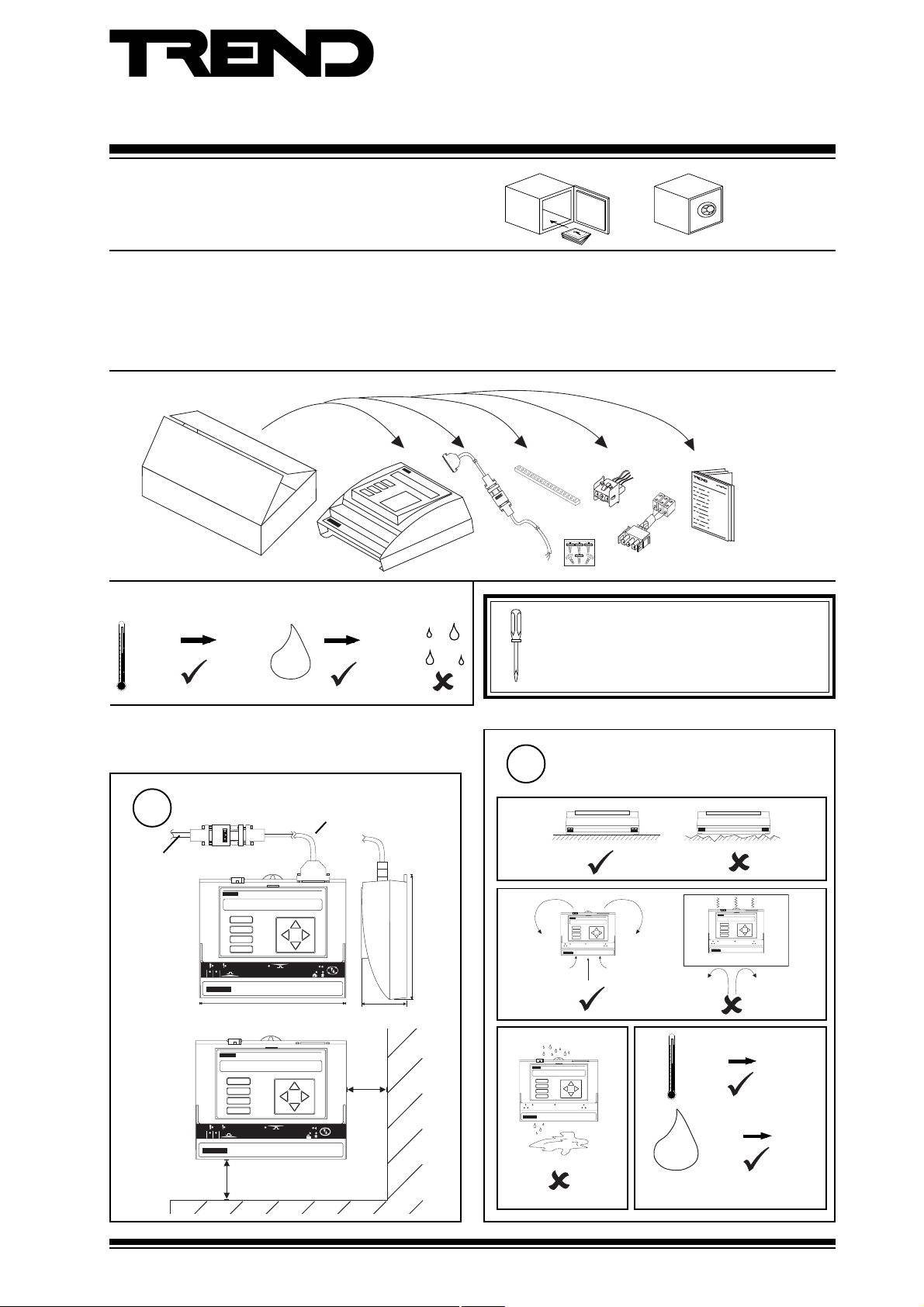
1 Unpacking.......................................................................... 1
2 Storing ................................................................................ 1
3 Installation .......................................................................... 1
3.1 Installation - Mounting ....................................................... 1
1 UNPACKING
2 STORING
-10 °C
(14 °F)
+50 °C
(122 °F)
0
H2O
90 %RH
3.2 Installation - Configuration ................................................ 4
4 Replacing the Battery ....................................................... 8
5 Zero Address/Baud Rate Switch Reset ........................ 11
6 Mounting in an Enclosure,ENCLS/... ............................. 12
7 Disposal ........................................................................... 12
USA/24
version only
NBOX/XNC220
Installation
EJ105383
Instructions
TG200019
/485
option only
/24V
version only
It is recommended that the installation should
comply with the HSE Memorandum of Guidance
on Electricity at Work Regulations 1989.
For USA install equipment in accordance with
the National Electric Code.
3 INSTALLATION
3.1 Installation - Mounting
Dimensions
1
3 m (9’9.9”)
DP
A
B
C
D
1
2
230 mm (9.05”)
A
B
C
D
1
2
100 mm (3.94”)
TX
XNC220
OK
TX
RX
XNC220
OK
RX
DP
40 mm (1.57”)
70 mm (2.75”)
50 mm
(1.97”)
181 mm (7.12”)
Requirements
2
a
b
c
1
6 7 8
9 101112
2 3 4 5
LA N
LA N
LA N
LA N
TX R X
X N C 2 2 0
TX R X
1
6 7 8
9 101112
13
2 3 4 5
15
14
X N C 2 2 0
d
0 °C
(32 °F)
LA N
LA N
TX R X
24 V
13
15
14
X N C 2 2 0
0 %RH
+45 °C
(113 °F)
90 %RH
H2O
Protection IP30, NEMA 1
NBOX/XNC220 Installation Instructions TG200019 Issue 1/E 14/1 1/06
1
Page 2
NBOX/XNC220 Installation Instructions
XNC220
TX
RX
OK
1
2
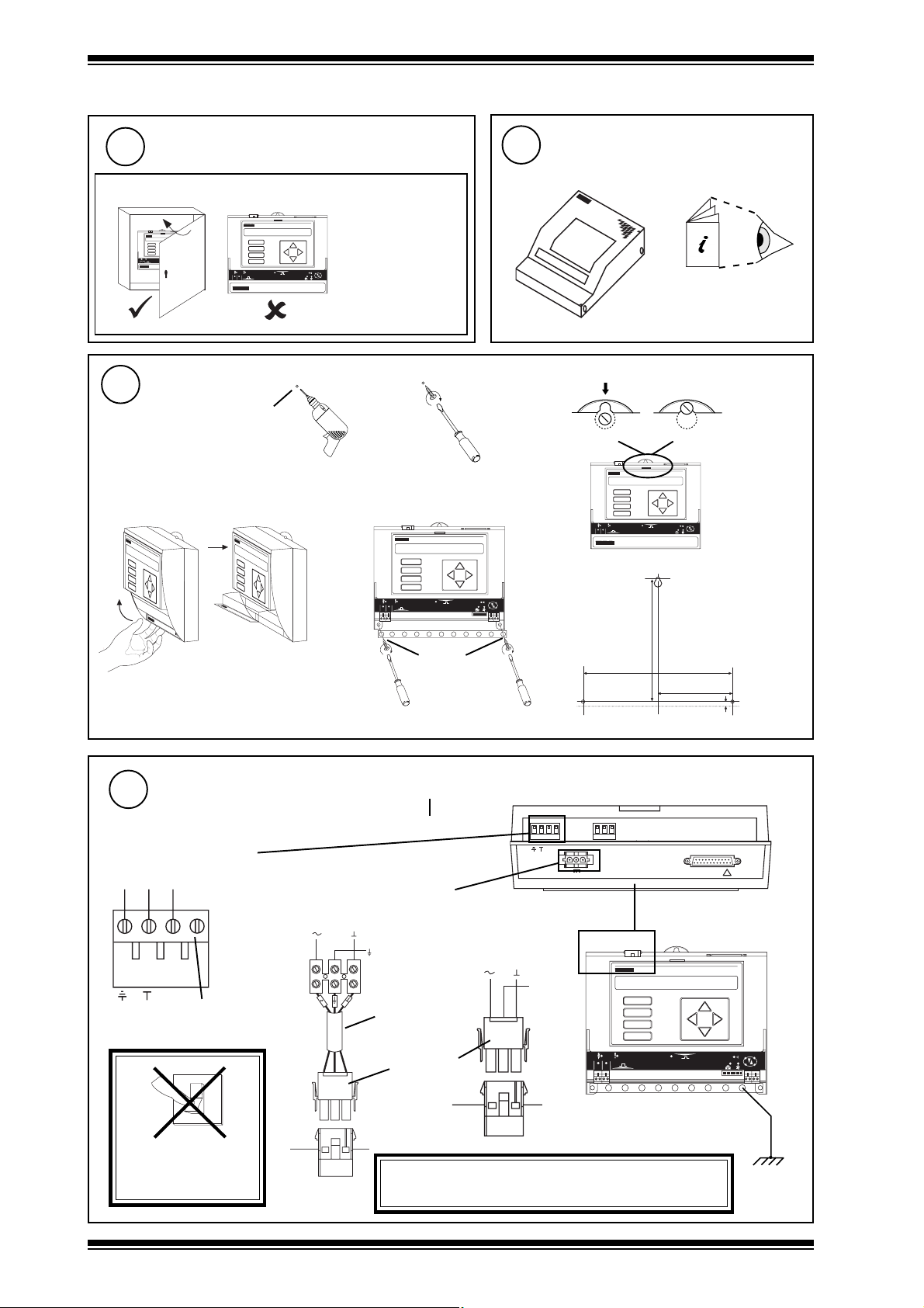
3.1 Installation - Mounting (Continued)
Requirements (Continued)
2
e
NBOX/XNC220/USA only
OK
OK
LAN
LAN
TX
RX
TX
TX RX
RX
1
2
XNC220
Mounting
4
e
The unit is UL rated
as 'UL916, listed open
energy management
OK
TX
1
2
RX
XNC220
equipment'
a b
Ø 6 mm
(0.24”)
Mount MBOX
3
if using ENCLS/MBOX/IQ22x
ENCLS/MBOX/IQ22x
Installation Instructions
TG200203
c
f
A
B
C
D
1
2
12345678910
OK
TX
RX
d
Connect Input Power
5
NBOX/XNC220 Consumption > 13 VA
Terminal size 0.5 to 2.5 mm2 (14 to 20 AWG)
230 Vac version
E N L
~
E N L
no
connection
0
I
24 Vdc:
24 Vac:
+24V 0V
24 Vac
EJ105383
24 V version
0V
Earth
adaptor
supplied
24V
Mat-N-Loc
connector
Ø 6 mm
(0.24”)
/USA only
24 Vdc:
24 Vac:
+24V 0V
24 Vac
Yellow
172 mm (6.77”)
209 mm (8.23”)
2 3 0 V
0V
N C N O C N C N O C N C N O C N C N O C N C N O C
~
~
2 4 V
M O D E M
Earth
Green
Blue
A
B
C
D
1
2
Earth (ground) the bus bar separately
104.5 mm (4.11”)
7 mm (0.28”)
R D S /R S 2 3 2
!
OK
TX
RX
12345678910
DO NOT APPLY
POWER
2
WARNING: This apparatus must be earthed
(grounded) using input power connector.
NBOX/XNC220 Installation Instructions TG200019 Issue 1/E 14/1 1/06
Page 3
Installation Instructions NBOX/XNC220
TRT
R
T
R
T
R
T
T
R
R
e a r t h ( g r o u n d ) b u s
X
T
T
R
R
T X -
T X + R X -
R X +
L A N
( g
n+1
n
Æ
a
Æ
b
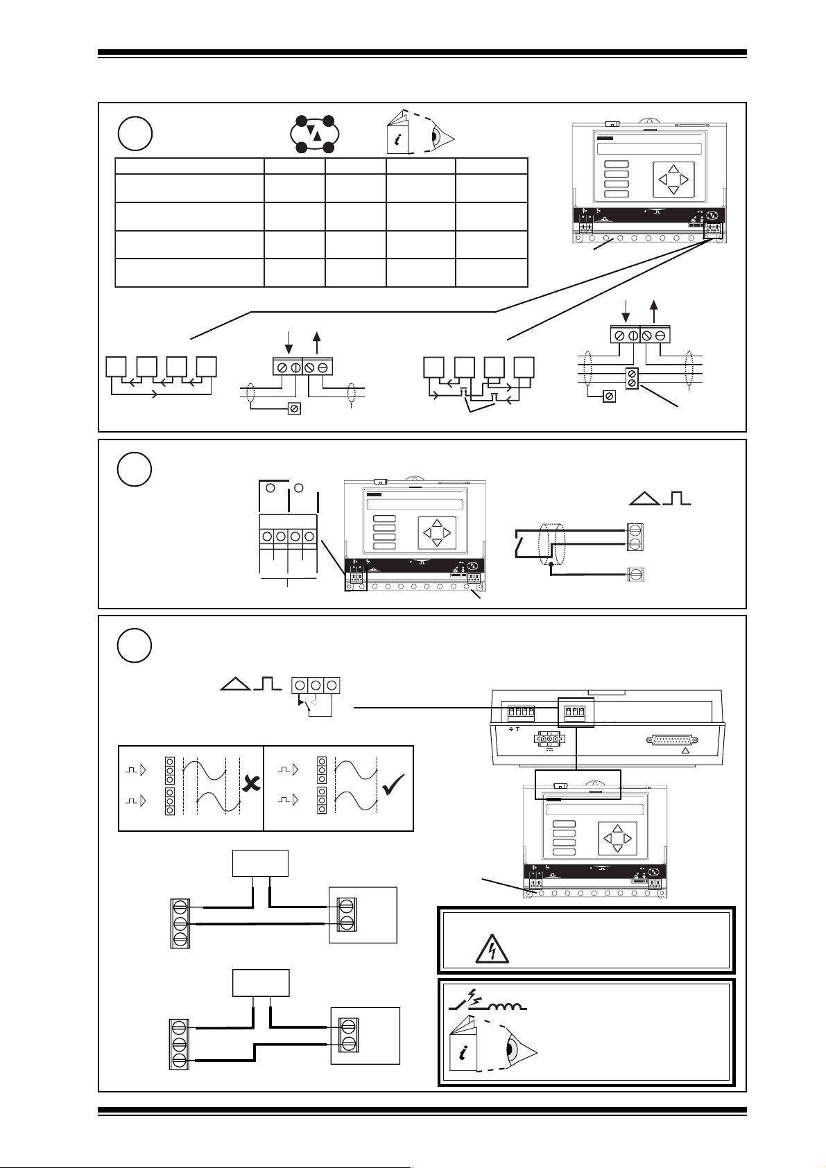
3.1 Installation - Mounting (Continued)
Connect Network
6
elbaCduab2k1duab6k9duab2k91seriWfo.oN
2819nedleB
7029nedleB
002/FH/22/1/1/PTmetsysQI
m0001
m0001
dy0901(
m0001
)1678nedleB(
002/FH/22/2/2/PTmetsysQI
m0001
)3278nedleB(
Terminal size 0.5 to 2.5 mm2 (14 to 20 AWG)
L A N
2 wire
T X -
R X +
R
R
T X + R X -
e a r t h ( g r o u n d ) b u s
Connect Inputs (external connection channels 1, 2, configuration channels IN1, IN2)
7
1
IQ system TP/1/1/22/HF/200
(Belden 8761) cable
recommended for all inputs.
Cable size 0.5 to 2.5 mm
2
(14 to 20 AWG) - Cu only
D i g i t a l O n l y I n p u t s
2
I N 1 C I N 2 C
)sdy0901(
)sdy0901(
m0001
m0001
)s
)sdy0901(
m007
)sdy0901(
)sdy567(
m005
)sdy0901(
)sdy545(
polarity independent
T
T
X
A
B
C
D
1
2
Network Engineering
Manual 92-1735
m007
)sdy567(
m005
)sdy545(
m053
sdy083(
)
m052
)sdy072(
2
2
2
4
4 wire
R
T
additional terminals
R
R
T
T
OK
TX
RX
12345678910
earth (ground) bus
1
earth (ground) bus
R
T
Digital inputs
A
B
C
D
2
(channels 1 to 2)
I N n
C ( 0 V )
e a r t h
OK
TX
RX
12345678910
additional
terminals
r o u n d) b u s
Connect Relay Output (external channel 16,
configuration channel OP8)
8
Cable size 0.5 to 2.5 mm2 (14 to 20 AWG) - Cu only
Driver on, load on
C
NO
NC
n
Driver off, load on
C
NO
NC
n
NBOX/XNC220 Installation Instructions TG200019 Issue 1/E 14/1 1/06
power
power
16
NC NO C
n+1
n
Æ
Æ
OP8
a
a
load
load
240 Vac single phase 8 A (resistive 5A (inductive, Cos Ø = 0.4)
20 Vdc at 5 A(resistive), 20 Vdc at 5A (inductive)
24 Vdc (inductive) 2A
For NBOX/XNC220/USA, UL rating applies up to 30 V
2 3 0 V
earth (ground)
bus
N C N O C N C N O C N C N O C N C N O C N C N O C
~
~
2 4 V
1
2
M O D E M
A
B
C
D
TX
12345678910
R D S /R S 2 3 2
!
OK
RX
WARNING:The wires may be connected to hazardous
voltages. Disconnect power
before attempting any wiring.
Arc suppression
recommended
Relay Output Arc Suppression
Installation Instructions TG200208
3
Page 4
NBOX/XNC220 Installation Instructions
1234 5678 9 10
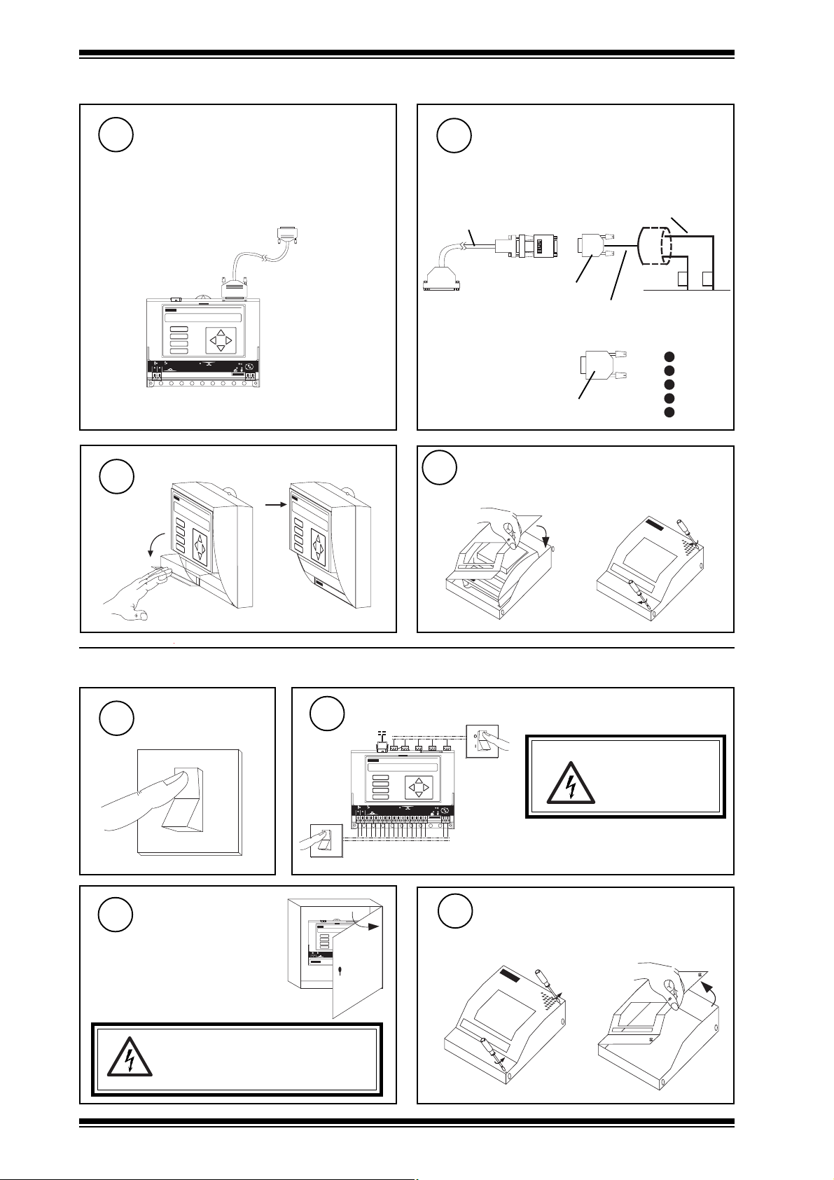
3.1 Installation - Mounting (Continued)
Connect to 3rd Party System (RS232)
9
not /485
Pin 2 = RX
Pin 3 = TX
3rd party system
Pin 7 = ground
A
B
C
D
1
2
12345678910
OK
TX
RX
Close Flap
11
Connect to 3rd Party System (RS485)
10
/485 only
2-wire RS485: cable supplied
ensure RS232/RS485 converter
is connected correct way round
RS232 ← → RS485
9 Way D type male
4-wire RS485: construct cable
9 Way D type male
Close MBOX
12
If fitted in ENCLS/MBOX/IQ22x
ensure correct
polarity
red
AB
3 m (9’ 9.9”) cable supplied
2 RXA
7 RXB
8 TXA
3 TXB
1 GND
ba
blue
3.2 Installation - Configuration
Switch Off
1
O
I
Open Panel
3
NBOX/XNC220/USA only
The unit is UL rated as 'UL916, listed
open energy management
equipment'
WARNING:
Opening the panel may expose dangerous
voltages.
417-IEC-5036
Isolate I/O, Network
2
DP
A
B
C
D
1
2
O
I
OK
TX
RX
Open MBOX
4
if unit fitted in ENCLS/MBOX/IQ22x
OK
LAN
TX
1
1
RX
2
678
9101112
2345
13
15
14
XNC220
a
WARNING: The connecting leads
may be connected to
supplies. Isolate
before touching.
b
4
NBOX/XNC220 Installation Instructions TG200019 Issue 1/E 14/1 1/06
Page 5

Installation Instructions NBOX/XNC220
12345678910
A
B
C
D
TX
RX
OK
1
2
12345678910
A
B
C
D
TX
RX
OK
1
2
3.2 Installation - Configuration (continued)
Open Flap
5
WARNING: Removal of the cover exposes
Set the Network Baud Rate
7
O N
1
284
1 6
3 2
6 4
9 K 6
1 9 K 2
B A U DA D D R E S S
9 K 6
1 9 K 2
1 K 2
1 K 2
= 19k2 baud
dangerous voltages.
417-IEC-5036
Trend Baud Rate = B
Disconnect I/O
6
= B
= B
= B
1 K 2
9 K 6
1 9 K 2
= 9k6 baud
1 K 2
9 K 6
1 9 K 2
= B
= 1k2 baud
Set the Network Address
8
Close Flap
9
Address = A
O N
e.g.
1
284
1 6
3 2
6 4
1 9 K 2
B A U DA D D R E S S
Address = 2 + 16 = 18
1 K 2
9 K 6
SET
NOT SET
/
= A
or
address
A+1
1, 4 to 9, 11 to 119
0, 2, 3, 10 or >119
NBOX/XNC220 Installation Instructions TG200019 Issue 1/E 14/1 1/06
* Note that a second address on the network is used by Comport
(default COM port 2 uses address switch setting +1). It can be
set up by software for communication to the TCL part
= A and
A+1*
= A
/
or
A+1
NBOX/XNC220
/
= A
or
A+1
5
Page 6

NBOX/XNC220 Installation Instructions
N B O X / X N C 2 2 0
?
O
I
3.2 Installation - Configuration (Continued)
10
12
Switch On
0
I
Check Network
A
B
C
D
1
2
11
a power
b
OK
TX
RX
12345678910
Check Controller
(green)
watchdog
(red)
aRX
(yellow)
bTX
(yellow)
c OK
(green)
Check input
power
NBOX/XNC220
Faulty
A
B
C
D
OK
TX
1
2
N B O X / X N C 2 2 0
RX
12345678910
?
L A N
OK
XNC220 Faulty
T X - T X + R X - R X +
Configure Device Part
13
SET
*.IQ2
Device
Part
TCL
Part
NBOX/XNC220
configure comport modules
store modules
also set time, day, date
L A N
T X - T X + R X - R X +
IQ Configuration Manual
90-1533
NBOX/XNC220 Data Sheet
TA200018
SET Manual TE200147
NBOX/XNC220
Address set
on address
switch
Network Address Invalid
0, 2, 3 or >119
NBOX/XNC220
OK
Check network cabling for
short circuits with a multimeter
(NOT Megger)
Check baud rate .
Power up other nodes until faulty
node is found (OK ). Correct
fault.
Create and Download TCL Code
14
TCL Tool
TCL code
Device
Part
TCL
Part
NBOX/XNC220
Trend Custom Language Manual TE200017
(Creation)
TCL Engineering Course Notes
(Downloading)
NBOX/XNC220
Address set on address
switch
SET
6
NBOX/XNC220 Installation Instructions TG200019 Issue 1/E 14/1 1/06
TCL Tool
Page 7

Installation Instructions NBOX/XNC220
3.2 Installation - Configuration (Continued)
Compile and Run TCL Code
15
Compile Run
Set up RS232/RS485 Converter Switch
16
/485 only
RS232 ← → RS485
OK
TX
1
2
RS485 port is 4-wire
RS485 port is 2-wire
RS485 receiver is enabled only
when transmitter is disabled (RS485)
RS485 receiver is always enabled
RS485 transmitter enable is controlled
(Slave on 4-wire RS485)
RS485 transmitter always enabled
(Master on 4-wire RS485)
RX
12345678910
SW1 SW2 SW3 SW4 SW5 SW6
ON
2 3 4 5 6
1
OFF
ON
OFF
ON
OFF
ON
OFF OFF OFF
OFF OFF ON
OFF ON OFF
OFF ON ON
ON OFF OFF
ON OFF ON
ON ON OFF
ON ON ON
O N
1 2 3 4
5 6
do not set to this
1200,8
2400,8
4800,8
9600,8
do not set to this
19200,8
do not set to this
2 W I R E
R X E N
T X E N
A D E 2
A D E 1
A D E 0
TCL Tool
NBOX/XNC220
Address set on address
switch
Test Inputs
17
Switch off
a
Switch on
c
d
O
I
TCL Engineering Course
Notes
b
0
I
X N C 2 2 0
1
2
A
B
C
D
12 34 56 78 91 0
A
B
C
D
OK
TX
RX
12345678910
18
a
c
Test Output
Switch off
O
I
Switch on
0
I
b
d
X N C 2 2 0
Test System
19
A
B
C
D
1
2
OK
TX
RX
12345678910
NBOX/
XNC220
Lan
Δ V
Δ V
Device
A
B
C
D
1
2
OK
TX
RX
12345678910
NBOX/XNC220 Installation Instructions TG200019 Issue 1/E 14/1 1/06
7
Page 8

NBOX/XNC220 Installation Instructions
1234 5678 9 10
3.2 Installation - Configuration (Continued)
Backup Device Part
20
SET
(compare)
*.IQ2
Device
Part
NBOX/XNC220
22
NBOX/XNC220/USA only
The unit is UL rated as 'UL916,
listed open energy
management equipment'
TCL
Part
SET
Close Panel
SET Manual TE200147
NBOX/XNC220
Address set on
address switch
OK
OK
LAN
LAN
TX
RX
TX
TX RX
1
2
XNC220
RX
Close MBOX
21
if fitted in ENCLS/MBOX/IQ22x
a
b
4 Replacing Battery
Upload Strategy
1
SET
X.IQ2
Device
Part
NBOX/XNC220
Isolate I/O, Network
4
A
B
C
D
1
2
O
I
TCL
Part
TCL Code
2
SET Manual TE200147
NBOX/XNC220
Address set on
address switch
SET
DP
WARNING: The connecting leads
may be connected to supplies. Isolate
OK
TX
RX
before touching.
Ensure you have original
TCL data
TCL Code
Switch Off
3
O
I
8
NBOX/XNC220 Installation Instructions TG200019 Issue 1/E 14/1 1/06
Page 9

Installation Instructions NBOX/XNC220
12345678910
A
B
C
D
TX
RX
OK
1
2
TX
RX
OK
1
2
12345678910
A
B
C
D
4 Replacing Battery (continued)
Open Panel
5
NBOX/XNC220/USA only
The unit is UL rated as 'UL916,
listed open energy management
equipment'
WARNING:
Opening the panel may expose
dangerous voltages.
417-IEC-5036
Open Flap
7
Open MBOX
6 If unit fitted in ENCLS/MBOX
OK
LAN
TX
1
2
1
2345
RX
678
9101112
13
15
14
XNC220
a
b
Remove Cover
8
b
c
a
WARNING: Removal of the cover
exposes dangerous
voltages.
417-IEC-5036
SAFT LM 2450 3V
9
Replace Battery
12 3 45 67 8 910
Warning: This lithium battery must not be
recharged, disassembled, burnt or short
circuited. Misuse may cause explosion or fire.
Dispose of carefully. Refer to Health and Safety
Executive Guidance Note GS43.
Switch On
11
12
Wait
Caution: This unit contains static sensitive devices. Suitable
anti-static precautions should be taken throught this
operation to prevent damage to the unit.
BSEN10015/1 Basic Specification: protection of
electrostatic sensitive devices.
Replace Cover
10
Reset RAM
13
Close Flap
14
If not IQ2v3 (IQ2v3 will reset
RAM automatically)
Switch off. Complete Zero
Address/Baud Rate Switch
Reset section steps 2 to 7.
0
10s
I
NBOX/XNC220 Installation Instructions TG200019 Issue 1/E 14/1 1/06
9
Page 10

NBOX/XNC220 Installation Instructions
123 4 5 6 7 8910
4 Replacing Battery (Continued)
Download Strategy
15
also set time, day, date
Download TCL Code
16
TCL Tool
Device
Part
SET
X.IQ2
Device
Part
NBOX/XNC220
TCL code
TCL
Part
NBOX/XNC220
TCL
Part
SET Manual TE200147
NBOX/XNC220
Address set on
address switch
SET
NBOX/XNC220
Address set on address
switch
TCL Tool
TCL Engineering Course Notes
Compile and Run TCL Code
17
Compile Run
Close MBOX
18
If fitted in ENCLS/MBOX/IQ22x
a
b
TCL Tool
Close Panel
19
OK
OK
LAN
LAN
TX
RX
TX
TX RX
1
2
NBOX/XNC220/USA only
The unit is UL rated as
'UL916, listed open energy
management equipment'
XNC220
RX
NBOX/XNC220
Address set on address
switch
20
TCL Engineering Course
Notes
Reconnect Input power to I/O,
Network
DP
A
B
C
D
1
2
OK
TX
RX
10
NBOX/XNC220 Installation Instructions TG200019 Issue 1/E 14/1 1/06
Page 11

Installation Instructions NBOX/XNC220
1
284
1 6
3 2
6 4
1 K 2
9 K 6
1 9 K 2
B A U DA D D R E S S
O N
5 Zero Address/Baud Rate Switch Reset
Backup, Switch Off, Isolate,
1
Open Flap
Complete 'Replacing the Battery'
steps 1 to 7
Set All Switch Poles
to Zero
3
O N
1
284
1 6
3 2
6 4
1 K 2
9 K 6
1 9 K 2
A D D R E S S
B A U D
Note the Network Address
2
and Baud Rate
A
B
C
SET
NOT
SET
O N
1
284
1 6
3 2
6 4
1 9 K 2
B A U DA D D R E S S
e.g.
Address = 2 + 16 = 18
4
Switch on
D
1
2
1 K 2
9 K 6
1 9 K 2
1 K 2
9 K 6
= 19k2 baud
1 K 2
9 K 6
1 9 K 2
= 9k6 baud
1 K 2
9 K 6
1 9 K 2
= 1k2 baud
OK
TX
RX
12345678910
0
I
A
B
C
D
1
2
OK
TX
RX
12345678910
Wait for Relays
5
NOT
SET
Address = 0 Baud = 0
Reset the Network Baud Rate
6
A
B
C
D
1
2
O N
1
284
1 6
3 2
6 4
1 9 K 2
B A U DA D D R E S S
1 K 2
9 K 6
1 9 K 2
= 19k2 baud
1 K 2
9 K 6
1 9 K 2
= 9k6 baud
1 K 2
9 K 6
1 9 K 2
= 1k2 baud
Close Flap, Download Strategy,
8
Reconnect Power to I/O
Complete 'Replacing the Battery' steps 13 to 19
Trend Baud Rate = B
1 K 2
9 K 6
= B
= B
= B
12345678910
'click'
Reset the Network Address
7
A
B
OK
TX
RX
e.g.
C
D
1
2
12345678910
OK
TX
RX
Address = A
= B
Address = 2 + 16 = 18
SET
NOT SET
address
1, 4 to 9, 11 to 119
0, 2, 3, 10 or >119
NBOX/XNC220
= A
/
or
A+1
= A
/
= A
or
A+1
&
A+1
= A
/
or
A+1
Note that a second address on the network is used by a
comport (default COM port 2 uses address switch setting
plus 1). It can be set up by software for communication
to the TCL part
NBOX/XNC220 Installation Instructions TG200019 Issue 1/E 14/1 1/06
11
Page 12

NBOX/XNC220 Installation Instructions
6 Mounting in an Enclosure, ENCLS/...
Open Door
1
a
Remove Backplate
4
b
5
a
Drill Wall
2
560 mm
560 mm
Mount NBOX/XNC220 on
Backplate
M6
b
c
3
No. 12
OR
Mount on Wall
Replace Backplate
6
7 Disposal
WEEE Directive :
At the end of their useful life the packaging ,
product, and batteries should be disposed of
by a suitable recycling centre.
Do not dispose of with normal household waste.
Do not burn.
M6
Manufactured for and on behalf of the Environmental and Combustion Controls Division of Honeywell Technologies Sàrl, Ecublens, Route
du Bois 37,Switzerland by its Authorized Representative, Trend Control Systems Limited.
Trend Control Systems Limited reserves the right to revise this publication from time to time and make changes to the content
hereof without obligation to notify any person of such revisions or changes.
Trend Control Systems Limited
P.O. Box 34, Horsham, West Sussex, RH12 2YF, UK. Tel:+44 (0)1403 211888 Fax:+44 (0)1403 241608 www.trend-controls.com
Trend Control Systems USA
6670 185th Avenue NE, Redmond, Washington 98052, USA. Tel: (425)897-3900, Fax: (425)869-8445 www.trend-controls.com
12
NBOX/XNC220 Installation Instructions TG200019 Issue 1/E 14/1 1/06
 Loading...