

Page 1
Electricity Meter Node Controller
1234 5678 910
TX
RX
OK
1
2
123 456 789 10
TX
RX
OK
1
2
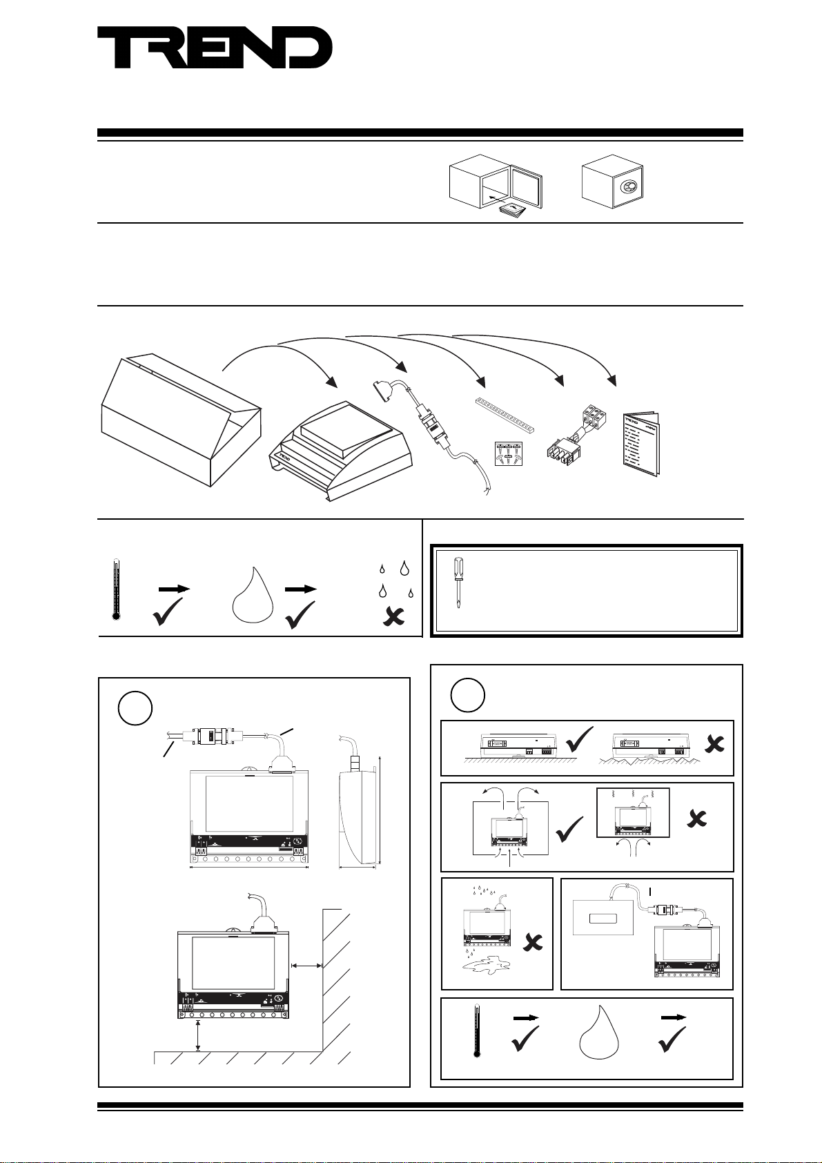
Important: Retain these instructions
Installation Instructions
NBOX/ENC2/S
CONTENTS
1 Unpacking .......................................................................... 1
2 Storage .............................................................................. 1
1 Unpacking
2 Storing
-10 °C
+50 °C
H O
0
2
90 %RH
3 Installation Instructions - Mounting ................................... 1
4 Installation Instructions - Configuration ............................ 4
5 Replacing the Battery ........................................................ 8
6 Disposal ............................................................................. 8
EJ105383
NBOX/ENC2/S
Installation
Instructions,
TG200270
/24V
version only
It is recommended that the installation should
comply with the HSE Memorandum of Guidance
on Electricity at Work Regulations 1989.
For USA install equipment in accordance with
National Electric Code.
3 Installation Instructions -Mounting
Dimensions
1
3 m (9’ 10”)
1
2
230 mm (9.06”)
1
2
100 mm (4”)
40 mm (1.57”)
O K
T X
R X
1 23 4 5 6 7 8 91 0
50 mm
O K
T X
R X
12 3 4 5 6 78 9 10
70 mm (2.76”)
(2”)
a
b
210 mm (8.27”)
c
e
Requirements
2
!
RD S /R S2 32
MO D E M
0 °C
(32 °F)
Protection : IP30
24 V
~
~
23 0V
NC NO C
+45 °C
(113 °F)
d
EM-MPO/..
H O
2
!
RD S /R S2 32
1
2
ENC2/S
0 %RH
24 V
MO D E M
~
~
23 0V
NC NO C
OK
TX
RX
1234 5678 910
> 3 m (9’ 10”)
1
2
90 %RH
OK
TX
RX
12345678910
NBOX/ENC2/S Electricty Meter Node Controller Installation Instructions TG200270 Issue 1/E 11/10/07
1
Page 2
NBOX/ENC2/S Installation Instructions
1 2 3 4 5 6 7 8 9 1 0
T X
R X
O K
1
2
2
2
th
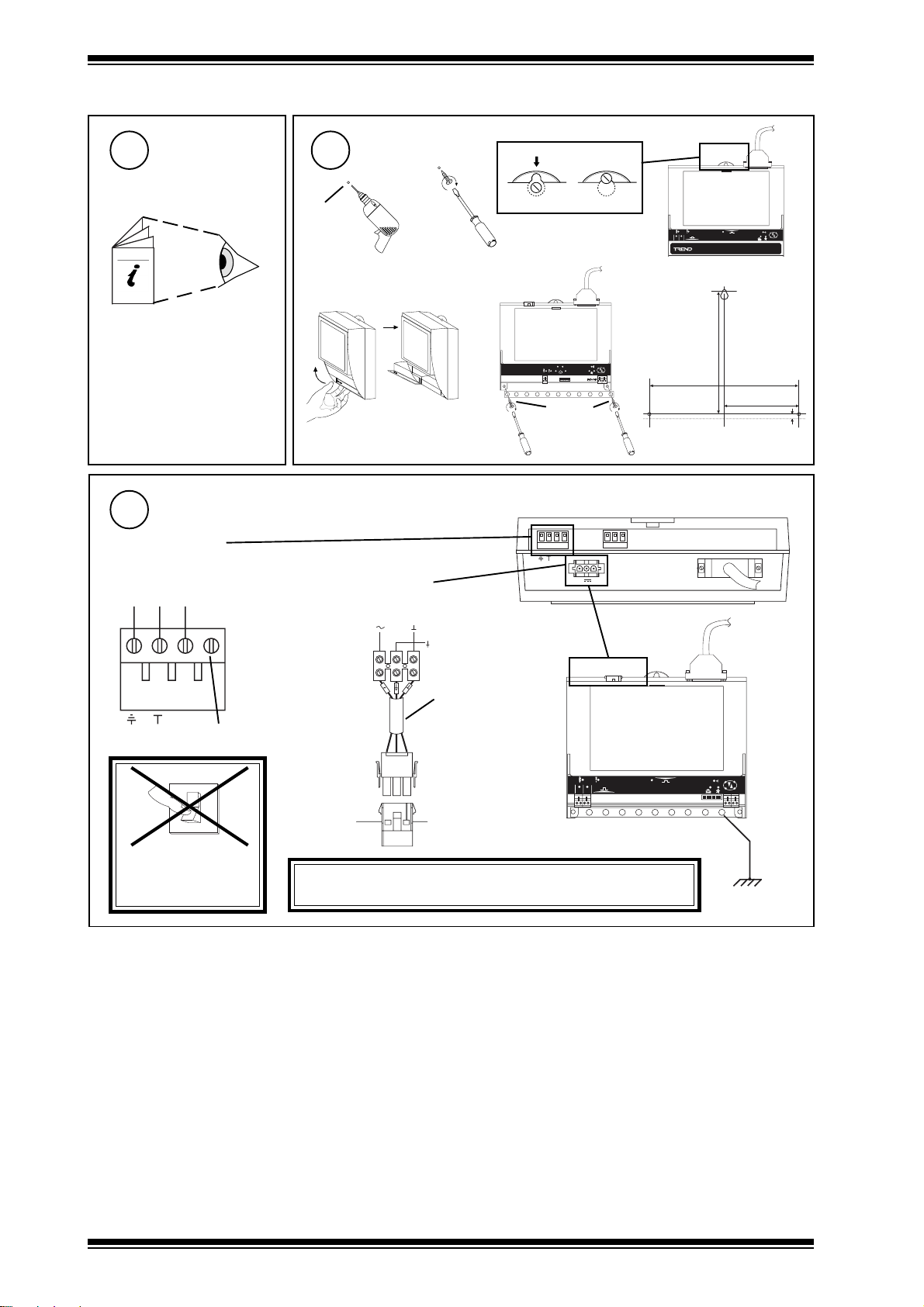
3 Installation Instructions - Mounting (continued)
Install EM-MPO/..
3 4
Appropriate EM-MPO/..
Installation Instructions
EM-MPO/STAR3DIN TG200770
EM-MPO/STAR3 TG200771
EM-MPO/SIRIO TG200772
Connecting Power
5
/230 version
terminal size 0.5 to 2.5 mm2 (14 to 20 AWG)
230 Vac
E N L
Ø 6 mm
(0.24”)
e
/24 version
4 Vdc:
4 Vac:
Mounting
a
+24V 0V
0V
24 Vac
b
cd
f
O K
D T R B
D T R A
T X R X
C T S BC T S A
Ø 6 mm
(0.24”)
NBOX/ENC2/S consumption < =13 VA
2 3 0 V
Ear
N C N O C
~
~
2 4 V
1
2
209 mm (8.23")
M O D E M
(6.77")
172 mm
R D S /R S 2 3 2
O K
T X
R X
E N C 2
104.5 mm
(4.11")
7 mm
(0.28")
!
Mat-N-Loc to
E N L
~
not connected
0
I
EJ105383
24V
(supplied)
Earth,
terminals adaptor
ground
the bus
DO NOT APPLY
POWER
WARNING: This apparatus must be earthed, grounded.
(via mains earth, ground, terminal)
bar
2
NBOX/ENC2/S Electricty Meter Node Controller Installation Instructions TG200270 Issue 1/E 11/10/07
Page 3
Installation Instructions NBOX/ENC2/S
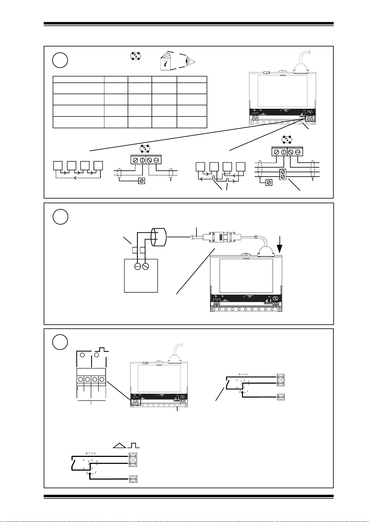
3 Installation Instructions - Mounting (continued)
Connect Network
6
elbaCduab2k1duab6k9duab2k91seriWfo.oN
2819nedleB
7029nedleB
002/FH/22/1/1/PTdnerT
)1678nedleB(
002/FH/22/2/2/PTdnerT
)3278nedleB(
m0001
)sdy0901(
m0001
)s
dy0901(
m0001
)sdy0901(
m0001
)sdy0901(
m0001
)sdy0901(
m0001
)sdy0901(
m007
083(
)sdy567(
m005
)sdy545(
Polarity independent
m007
)sdy567(
m005
)sdy545(
m053
)sdy
m052
)sdy072(
Network Engineering Manual, 92-1735.
2
2
2
4
1
2
O K
T X
R X
1 2 3 4 5 6 7 8 9 1 0
earth,
ground, bus
2 wire
T
TRT
R
R
T
R
R
R
terminal size 0.5 to 2.5 mm2 (14 to 20 AWG)
TX-
Connect to EM-MPO/..
7
Ensure correct polarity
A B
RS485
EM-MPO/..
Ensure RS232/RS485 converter
is connected correct way round.
RX+
TX+
RX-
earth,
ground, bus
red
blue
A B
4 wire
R
R
T
T
R
TRT
T
X
additional terminals
3 m (9’ 10”) cable supplied with ENC2/S
RS485 ← → RS232
1
2
R
T
ENC2/S
R
T
T
TX-
TX+
RX-
earth,
ground, bus
O K
T X
R X
1 2 3 4 5 6 7 8 9 1 0
RX+
T
T
R
R
X
additional terminals
Connect Inputs (external connection channels 1, 2, configuration channels IN1, IN2)
8
1
2
I N 1
C
I N 2
C
D i g i t a l O n l y I n p u t
1
2
1 2 3 45 6 7 8 9 1 0
O K
T X
R X
earth, ground, bus
Trend TP/1/22/HF/200 (Belden8761) cable recommended
for all inputs
Terminal size 0.5 to 2.5 mm2 (14 to 20 AWG)
Digital inputs
(channels 1 to 2)
INn
C (0V)
earth, ground, bus
NBOX/ENC2/S Electricty Meter Node Controller Installation Instructions TG200270 Issue 1/E 11/10/07
e.g. Connect External Synchronisation Contact to Input 1
External Maximum
Demand Sync Pulse
Note that for the ENC2/S strategy to use the external sync
pulse, W2, Enable Ext Sync, must be set to 1 - see section 4,
Configuration, step 14.
IN1
C (0V)
earth, ground, bus
3
Page 4

NBOX/ENC2/S Installation Instructions
1 2 3 4 5 6 7 8 9 1 0
T X
R X
O K
1
2
3 Installation Instructions - Mounting (continued)
Connect Relay Output (external channel 16, configuration channel OP8)
9
N C N O C
240 Vac single phase 8 A (resistive) 5 A (inductive, Cos ø = 0.4)
30 Vdc at 5 A (resistive) 20 Vdc at 5 A (inductive)
24 Vdc (inductive) 2 A
terminal size 0.5 to 2.5 mm2 (14 to 20 AWG)
Driver on, load on
p o w e r
C
N O
l o a d
N C
Driver off, load on
p o w e r
C
N O
l o a d
N C
2 3 0 V
N C N O C
~
~
2 4 V
M O D E M
R D S /R S 2 3 2
!
earth, ground bus
WARNING: The wires may be connected to hazardous
voltages. Disconnect power
before attempting any wiring.
Arc suppression recommended
Relay Output Art suppression
Installation Instructions TG200208
10
Close Flap
4
NBOX/ENC2/S Electricty Meter Node Controller Installation Instructions TG200270 Issue 1/E 11/10/07
Page 5

Installation Instructions NBOX/ENC2/S
4 Installation Instructions - Configuration
1
Switch off
Isolate I/O, Network
2
O
I
1
2
O
I
Open Flap
3
a
b
1 23 4 5 6 7 8 9 10
O K
T X
R X
WARNING: The connecting leads may be
connected to supplies. Isolate
before touching.
Disconnect I/O
4
WARNING: Removal of the cover
exposes dangerous
voltages.
417-IEC-5036
Set the Network Address
5
e.g.
O N
1
284
Address = 2+16 = 18
address
4 to 8, 11 to 118
0 to 3, 9, 10 or >119
1 6
3 2
6 4
SET
NOT SET
Set Network Baud Rate
6
O K
T X
1
2
1 K 2
9 K 6
1 9 K 2
B A U DA D D R E S S
Address = A
= A & A+1
1 23 4 5 6 7 89 1 0
ENC2/S
= A
/
or
R X
O N
1
284
1 6
3 2
6 4
1 K 2
9 K 6
1 9 K 2
19k2 baud
1 K 2
9 K 6
1 9 K 2
1
2
Baud Rate = B
= B
9k6 baud
A+1
1 K 2
9 K 6
= A
/
or
A+1
1k2 baud
1 9 K 2
1 K 2
9 K 6
1 9 K 2
= B
1 23 4 5 6 7 89 1 0
O K
T X
R X
= B= B
NBOX/ENC2/S Electricty Meter Node Controller Installation Instructions TG200270 Issue 1/E 11/10/07
5
Page 6

NBOX/ENC2/S Installation Instructions
4 Installation Instructions - Configuration (continued)
7
9
Close flap
Switch On
Check Converter Switch
(still set to defaults)
8
RS232 ← → RS485
ON
1234
2WIRE
56
RXEN
TXEN
ADE2
ADE1
ADE0
O K
T X
1
2
1 23 4 5 6 7 8 9 10
R X
SW1 ON
SW2 OFF
SW3 OFF
SW4 ON
SW5 OFF
SW6 OFF
Check ENC2/S
10
a (power)
0
I
(green)
Check supply
O K
T X
1
2
1 23 4 5 6 7 8 91 0
R X
11
Check Network
1
2
1 2 3 4 5 6 7 89 1 0
b (watchdog)
(red)
ENC2 Faulty
aRX
(orange)
N B O X / E N C 2
?
bTX
(orange)
N B O X / E N C 2
?
O K
T X
R X
c OK
(green)
Network Address invalid
0, 2, 3 or >119
T X - T X + R X - R X +
6
OK
NBOX/ENC2/S
ENC2/S faulty
OK
Check network cabling for
short circuits with a
multimeter (NOT Megger)
T X - T X + R X - R X +
O
I
Check baud rate
Power up other nodes until
faulty node is found
(OK ). Correct fault.
NBOX/ENC2/S Electricty Meter Node Controller Installation Instructions TG200270 Issue 1/E 11/10/07
Page 7
Installation Instructions NBOX/ENC2/S
0
I
0
I
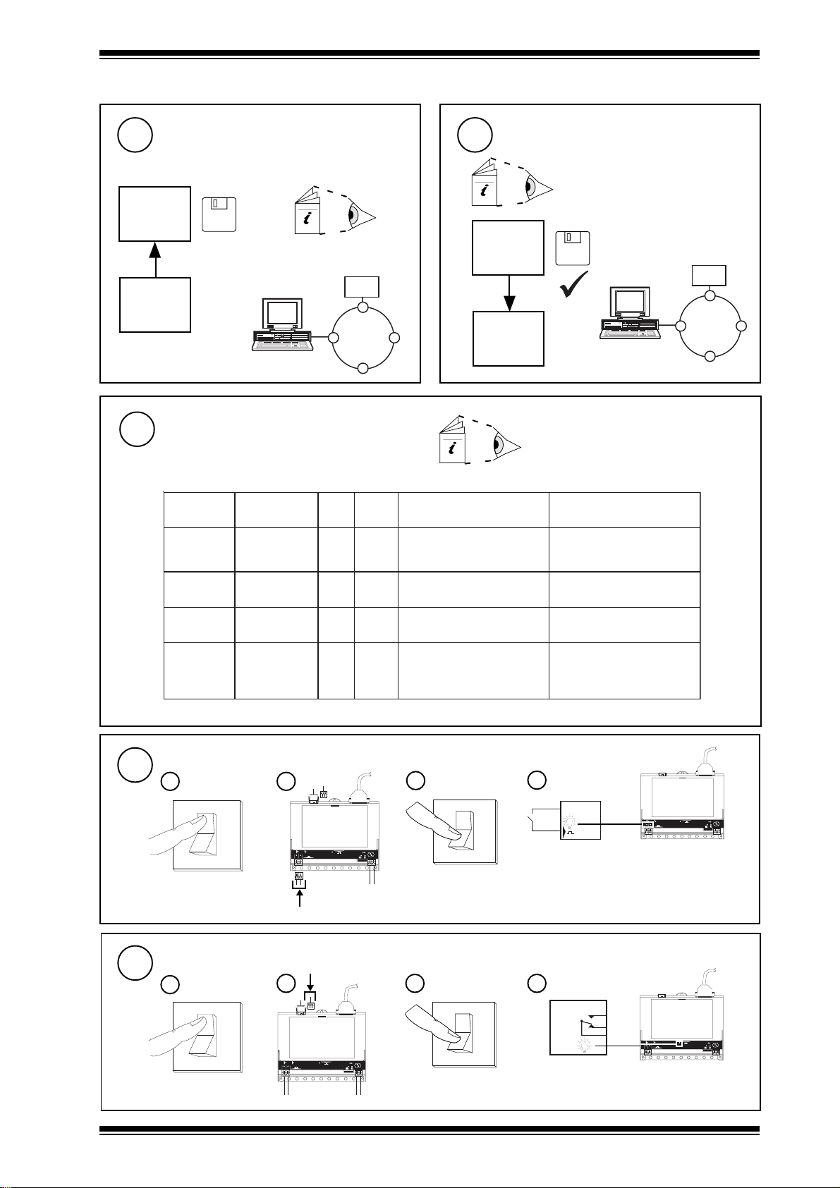
4 Installation Instructions - Configuration (continued)
12
14
Backup pre-configured ENC2/S Strategy
13
if further configuration is required,
else go to step 15
SET
SET Engineering Manual
X.IQF
ENC2/S
Configure adjustments
if required
metIlebalstinUtluafeDnoitcnuFegnahcotnehW
TE200147
ENC2/S
Configure
EM-MPO/.., ENC2/S Data Sheet
TA200268
IQ Configuration Manual 90-1533
SET Engineering Manual TE200147
SET
ENC2/S
X.IQF
ENC2/S
EM-MPO/.., ENC2/S Data Sheet TA200268
IQ Configuration Manual 90-1533
SET Engineering Manual TE200147
1WcnyStxEelbanE-0
2W
3WteseRrosilatoT-0
1K
also set time, date, day
Test Inputs
15
Switch off
a
mumixaMlanretxeehtselbanE
eslupnoitasinorhcnySdnameD
1tupnIno
dnameDxaM
teseR
-0
htsteseR
segasu
flahrAVk,AVk,Wke
sdnamedmumixamruoh
hrAVk,hAVk,hWkehtsteseR
C
8pets,gnixiF
lanretniruohflahsyaleD
emitesluptnI
1
2
ceS0
O K
TX
R X
12 3 45 6 78 91 0
mitruoh
Switch on
c
eslupe
yaled
b
O
I
htiweslupnoitasinorhcnys
flahelbatecneuqesottcepser
d
ENC2/S
cnyslanretxefi1otegnahC
,1teehSees-detcennoceslup
teserot1otegnahC
teserot1otegnah
ot0egnarnieulavotegnahC
otderiuqerfi)s92m92(9971
gnimitretemlanretxehctam
O K
TX
1
2
RX
12 34 5 67 89 10
Test Output
16
NBOX/ENC2/S Electricty Meter Node Controller Installation Instructions TG200270 Issue 1/E 11/10/07
Switch off
a
Switch on
b
O
I
1
2
O K
TX
R X
12 3 45 67 8 91 0
c
d
ENC2/S
O K
TX
1
2
RX
12 34 5 67 89 10
7
Page 8

NBOX/ENC2/S Installation Instructions
L
L
L
N
4 Installation Instructions - Configuration (continued)
17
18
Backup
Check system
1
2
3
SET
ENC2/S
ENC2/S
X.IQF
SET Engineering Manual
TE200147
LOAD
EM-MPO/..
ENC2/S
OK
TX
1
2
RX
12345678910
A
V
kW
5 Replacing the Battery
Replacing the Battery
1
This should only be undertaken by a qualified IQ System
Engineer as it involves a hot-replacement method. The
meter interface script program (TCL) is lost if the battery
is removed during power down. Contact your IQ system
Lan
6 Disposal
WEEE Directive :
At the end of their useful life the packaging,
product, and batteries should be disposed of
by a suitable recycling centre.
Do not dispose of with normal household waste.
Do not burn.
representative for advice.
Manufactured for and on behalf of the Environmental and Combustion Controls Division of Honeywell Technologies Sàrl, Ecublens, Route
du Bois 37,Switzerland by its Authorized Representative, Trend Control Systems Limited.
©Trend Control Systems Limited 2007. Trend Control Systems Limited reserves the right to revise this publication from time to
time and make changes to the content hereof without obligation to notify any person of such revisions or changes.
Trend Control Systems Limited
P.O. Box 34, Horsham, West Sussex, RH12 2YF, UK. Tel:+44 (0)1403 211888 Fax:+44 (0)1403 241608 www.trend-controls.com
Trend Control Systems USA
6670 185th Avenue NE, Redmond, Washington 98052, USA. Tel: (425)897-3900, Fax: (425)869-8445 www.trend-controls.com
8
NBOX/ENC2/S Electricty Meter Node Controller Installation Instructions TG200270 Issue 1/E 11/10/07
 Loading...