

Page 1
Important: Retain these instructions
EJ105383
+
+
HO
2
CONTENTS
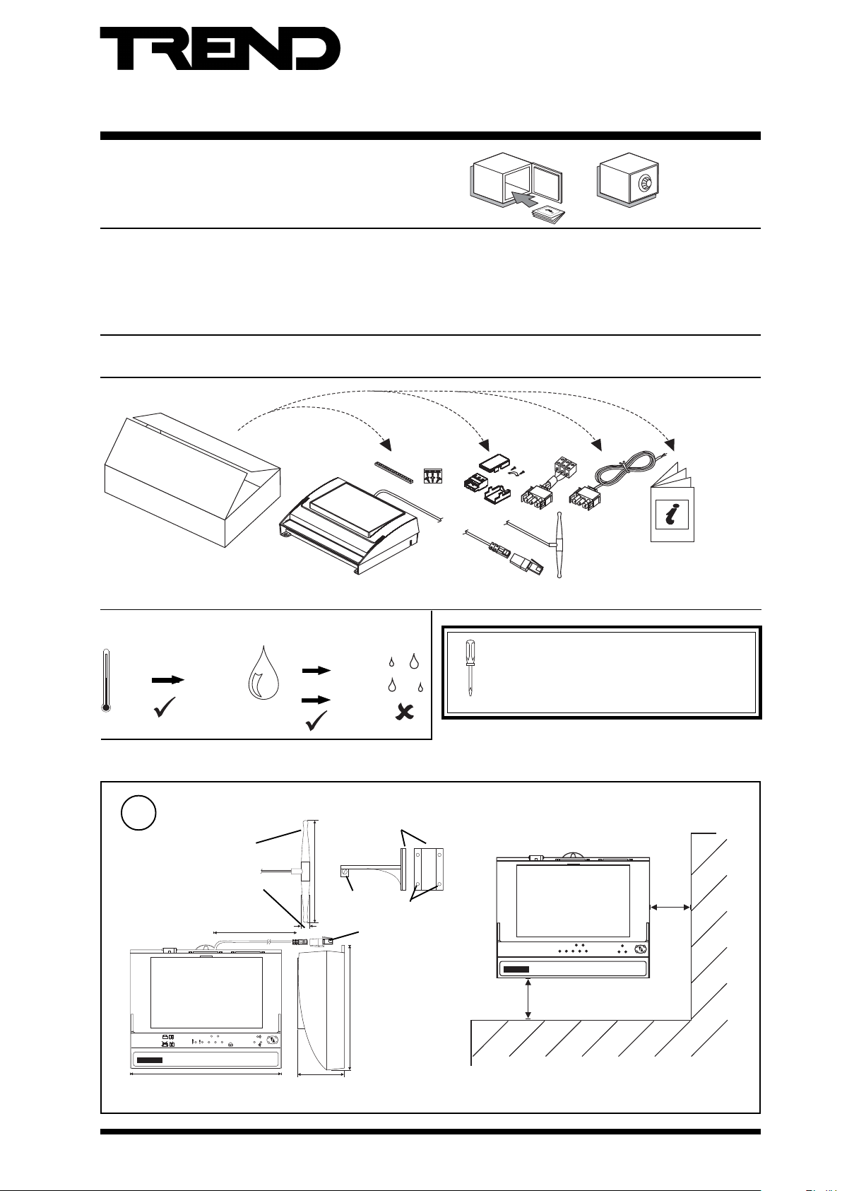
Installation Instructions
NBOX(B)TMNE, G , H
Trend Modem Node Controller
1.1 Unpacking 1
1.2 Storing 1
1.3 Installation - Mounting 1
1.4 Installation - Configuration 5
1 Installation Instructions
1.1 Unpacking
1.2 Storing
-10 °C
(14 °F)
+50 °C
(122 °F)
TMNE
0
TMNH, TMNG
20
90 %RH
90 %RH
2 Limitations of Use 14
3 Resetting the Node 16
4 Disposal 16
../24 only
3
8
3
5
0
1
J
E
../230 only
../24/USA
only
NBOX(B)/TMNE, G, H
Installation Instructions
TMNH only TMNG only
TG200729
It is recommended that the installation should
comply with the HSE Memorandum of Guidance
on Electricity at Work Regulations 1989.
For USA install equipment in accordance with
National Electric Code
1.3 Installation - Mounting
Dimensions
1
TMNG only
13 mm (0.5")
2 m (6' 7")
D T R A
TX RX
C T S BC T S A
TMN
OK
D T R B
230 mm (9.05”)
NBOX(B)TMNE, G, H Trend Modem Node Controller Installation Instructions TG200729 Issue 2, 07/01/2009 1
clamp
163 mm (6.5")
screw
70 mm
(2.75")
antenna bracket
50 mm
(2")
4 x Ø5mm (0.2”)
TMNH only
T M N
100 mm
(4")
181 mm (7.125")
Page 2
NBOX(B)TMNE, G, H Installation Instructions
T M N
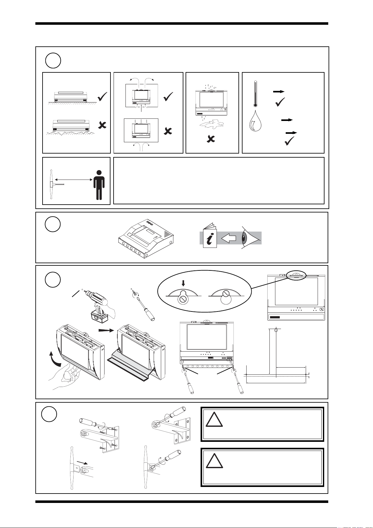
1.3 Installation - Mounting (continued)
Requirements
2
a
e TMNG only
>=20 cm (8")
Mount MBOX
3
if using
ENCLS/MBOX/IQ22x
b
T M N
T M N
c
d
0 °C
(32 °F)
TMNE
0 %RH
TMNH, TMNG
20 %RH
HO
2
Protection :IP30 (NEMA 2)
+45 °C
(113 °F)
90 %RH
90 %RH
f TMNG only
1 Mount antenna away from souces of interference (e.g. domestic appliances, computer
monitors or TV receivers, machinery with high HF leakage)
2 Do not operate near unshielded or susceptible equipment (e.g. some vehicles,
pacemakers, certain areas of hospital or medical centres, aircraft, areas designated
blasting areas).
ENCLS/MBOX/IQ22x
Installation Instructions
TG200203
Mounting
4
ab
Ø 6 mm
(0.24")
e
Mount Antenna
5
a
c
TMNG only
mount
vertically
c d
T M N
f
(6.77")
172 mm
Ø 6 mm
(0.24")
Only use the supplied antenna. An
b
emission regulations or invalidate type approval.
d
may result. Replace a damaged antenna
immediately.
unauthorised antenna could damage the
!
modem and may contravene local RF
Do not use the modem with a damaged
antenna. If a damaged antenna comes
!
into contact with the skin a minor burn
209 mm (8.23")
104.5 mm
(4.11")
7 mm
(0.28")
2 NBOX(B)TMNE, G , H Trend Modem Node Controller Installation Instructions TG200729 Issue 2, 07/01/2009
Page 3
Installation Instructions NBOX(B)TMNE, G , H
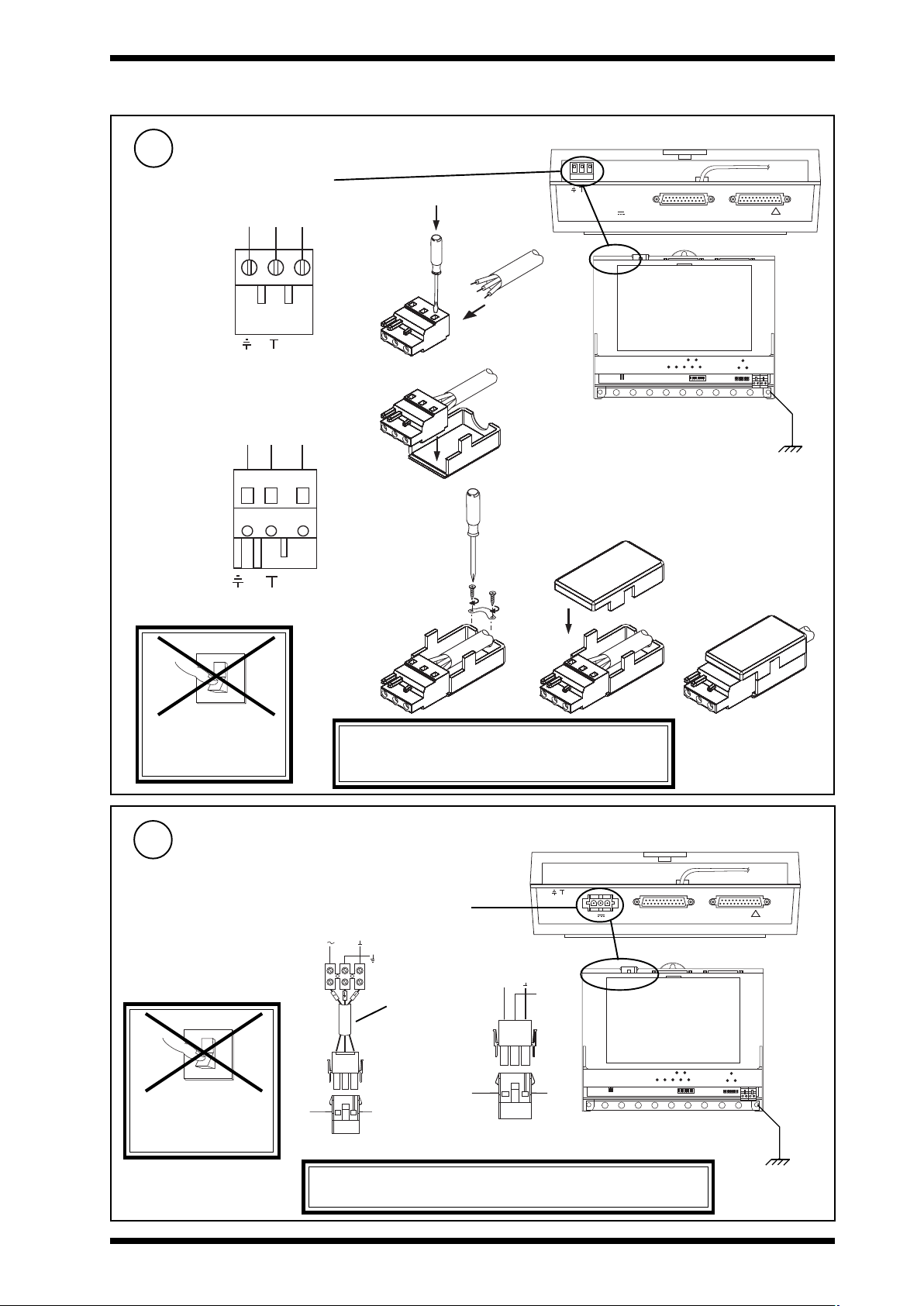
1.3 Installation - Mounting (continued)
Connecting Input Power Supply /230 version
6
Terminal size
0.5 to 2.5 mm
2
(20 to 14 AWG)
/230 230 Vac
either screw terminal
E N L
~
Earth N L
(ground)
or shrouded plug kit
E N L
NBOX(B)/TMN Consumption < = 7.5 VA
2 3 0 V
~
~
2 4 V
M O D E M
R D S / R S 2 3 2
!
a
b
Ground the bus
bar separately
Earth N L
~
(ground)
O
I
DO NOT APPLY
WARNING: This apparatus must be grounded
POWER
Connecting Input Power Supply /24 version
7
NBOX/TMN Consumption <=7.5 VA
/24 24 Vac or 24 Vdc
24 Vdc; 24 V oV
24 Vac; 24vac oV
O
I
24V
EJ105383
Earth (Ground)
Mat-N-Loc
to
terminals
adaptor
(supplied)
dce
(using mains earth, ground,
terminal).
2 3 0 V
~
~
2 4 V
/USA only
+ 2 4 V
2 4 V a c
0 V
0 V
~
E a r t h
( g r o u n d )
B l a c k
R e d
W h i t e
2 4 V d c :
2 4 V a c :
R D S / R S 2 3 2
M O D E M
!
DO NOT SWITCH
ON
WARNING: This apparatus must be grounded (using
green earth, ground, wire).
NBOX(B)TMNE, G, H Trend Modem Node Controller Installation Instructions TG200729 Issue 2, 07/01/2009 3
Ground the bus
bar separately
Page 4
NBOX(B)TMNE, G, H Installation Instructions
T
R
T
R
T
R
T
R
T
R
R
X
T
T
R
R
TX-
TX+
RX-
RX+
T
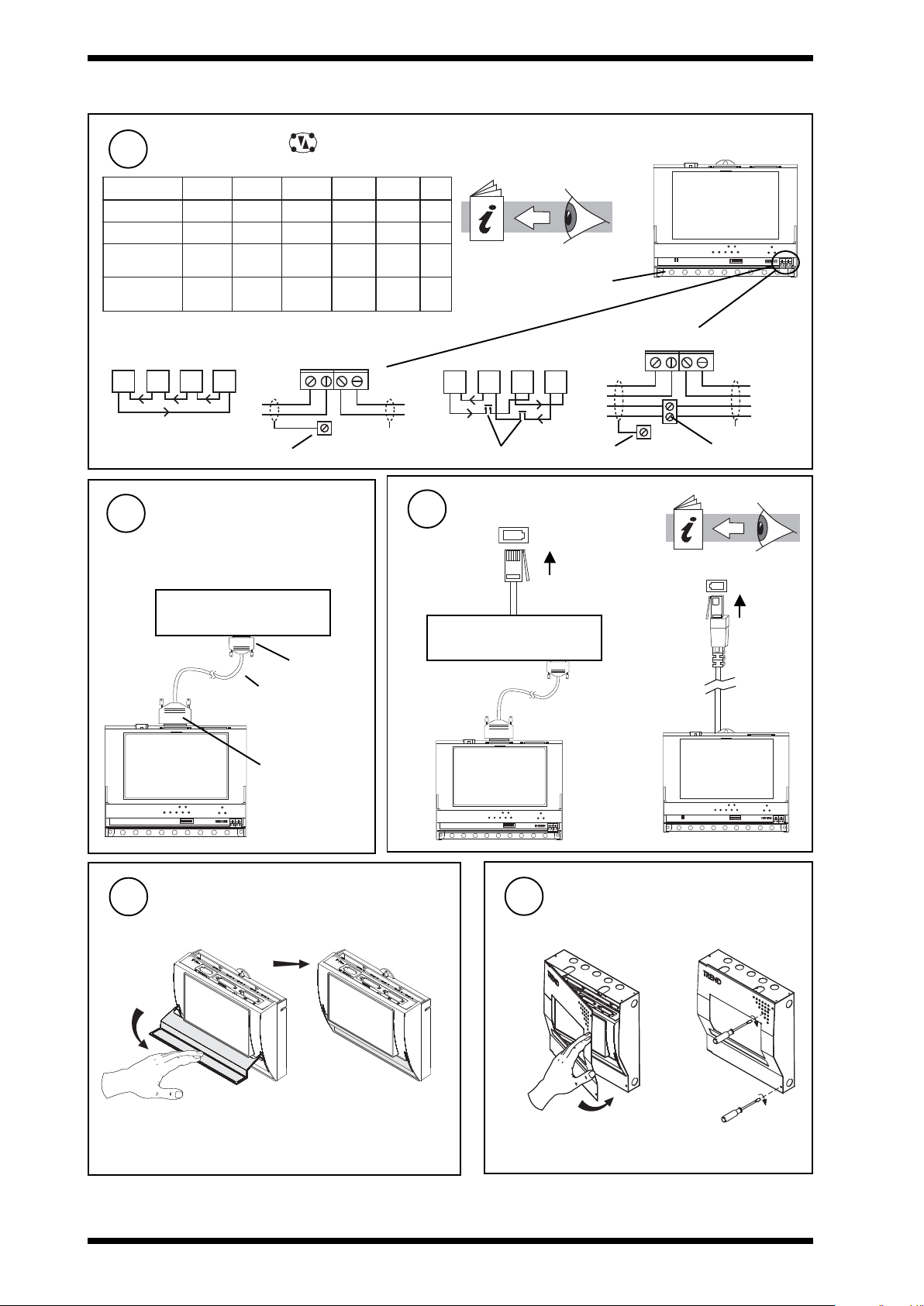
1.3 Installation - Mounting (continued)
Connect Network
8
elbaCduab2k1duab8k4duab6k9
2819nedleB
7029nedleB
dnerT
erT
dn
002/FH/22/1/1/PT
)1678nedleB(
002/FH/22/2/2/PT
)3278nedleB(
polarity independent
m0001
m0001
m0001
m0001
m0001
)sdy0901(
)sdy0901(
)sdy0901(
)sdy0901(
)sdy0901(
m0001
)sdy0901(
m0001
)sdy0901(
m0001
)sdy0901(
(unless direct connected to single device - old IQs or configuration)
m0001
)sdy0901(
m0001
)sdy0901(
m007
)sdy567(
m005
)sdy545(
Terminal sizes 0.5 to 2.5 mm2 (20 to 14 AWG)
2 wire
R
R
LAN A 4 wire
TX-
RX+
TX+
RX-
earth (ground) bus earth (ground) bus
Connect to Modem or
9
Terminal Adaptor
if TMNE
Modem/terminal adaptor
25 Way
D type Male
standard 25 way
cable (wired 1 to 1,
through to 25 to 25)
2k91
4k83
duab
m007
)sdy567(
m005
)sdy545(
m053
)sdy083(
m052
)sdy072(
fo.oN
duab
seriW
m005
2
)sdy545(
m053
2
)sdy083(
m052
)sdy072(
m521
)sdy531(
Network Engineering Manual
2
92-1735
4
earth (ground) bus
LAN A
R
R
T
T
T
X
T
T
additional terminals
Connect to PSTN (or ISDN)
10
Modem/terminal adaptor
R
R
T
additional terminals
connectif TMNE
See limitations of use (section 2)
if TMNH
connect
11
Close Flap
25 Way D type
Female
12
Close MBOX
if fitted in ENCLS/MBOX/IQ22x
ba
4 NBOX(B)TMNE, G , H Trend Modem Node Controller Installation Instructions TG200729 Issue 2, 07/01/2009
Page 5
Installation Instructions NBOX(B)TMNE, G , H
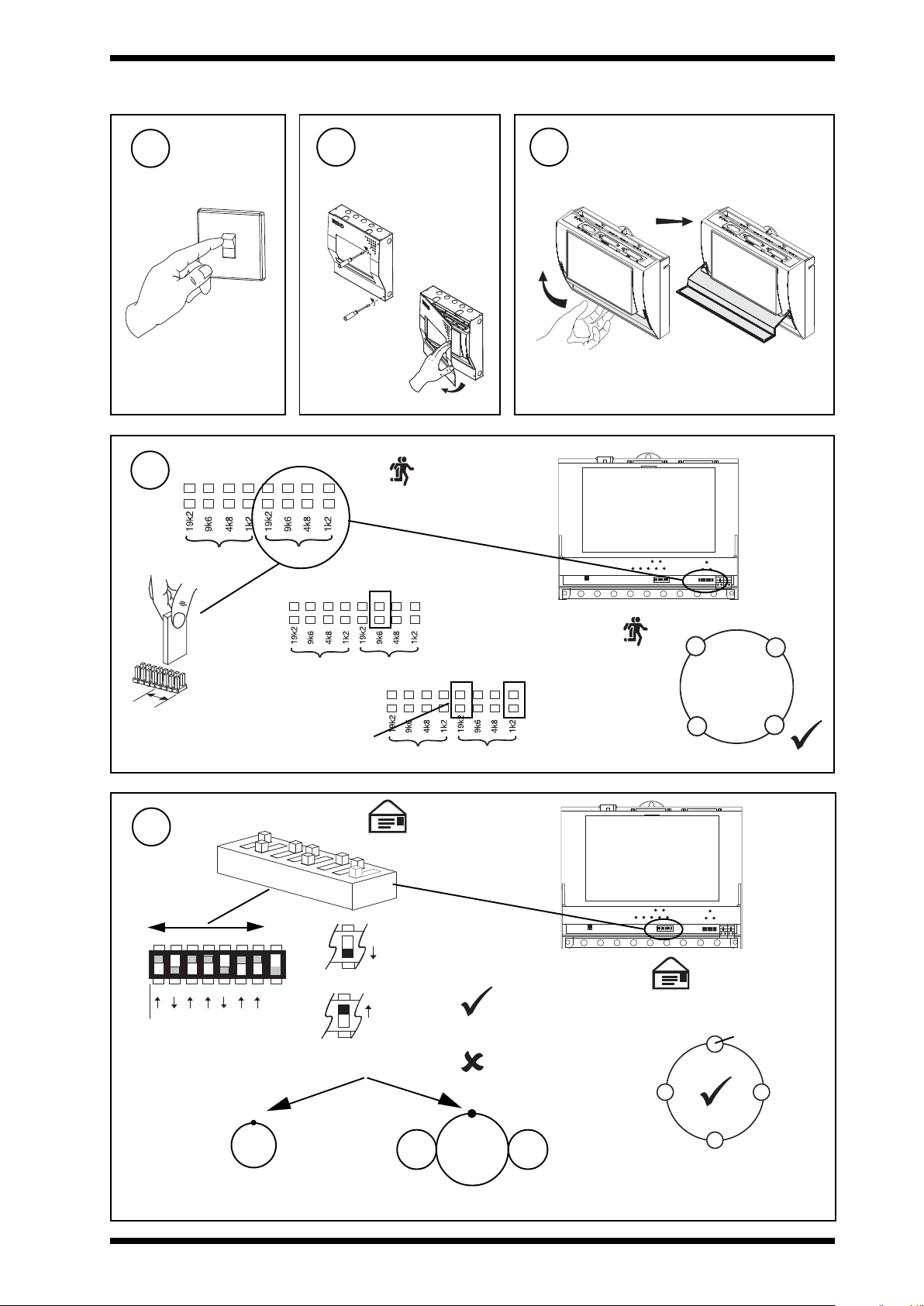
1.4 Installation - Configuration
Switch off
1
O
I
Set the Network Baud Rate
4
BAUD B BAUD A
Open MBOX
2
if unit fitted in
ENCLS/MBOX/IQ22x
3
Open Flap
a
b
(or Device A RS232
baud rate if connected
to single device)
BAUD A
move link to
set baud rate
(Baud A)
Set the Network Address
5
e.g.
O N
1
284
A D D R E S S
Address = 2 + 16 = 18
if position 'autosense' (see 1.4 step 19)
A = 1 to 99
autosense
device address
e.g 9k6
BAUD B BAUD A
or high baud rate 38k4
(only for use on high speed
internetwork segments)
Note: needs
extra link
D U M B
N O R M
1 6
3 2
6 4
TMN
Lan
BAUD B BAUD A
SET
NOT SET
Network Baud Rate = R1
(or RS232 to single device)
address
recommended:
11 to 99 device address on
Lan
100 to 114 Lan number on
internetwork
0, 2, 3,10 or >119
TMN
I/NLan Lan
A = 100 to 114
autosense
Lan number
= R1
Address = A
= A to A+5
/
= R1
= R1
= A
NBOX(B)/TMN
= A to A+5
/
= R1
= A to A+5
/
NBOX(B)TMNE, G, H Trend Modem Node Controller Installation Instructions TG200729 Issue 2, 07/01/2009 5
Page 6

NBOX(B)TMNE, G, H Installation Instructions
1.4 Installation - Configuration (continued)
Set Dumb/Normal switch
6
D U M B
O N
e.g.
N O R M
A D D R E S S
Set modem/terminal adaptor baud rate
7
BAUD B BAUD A
move link to
set baud rate
(Baud B)
NOTE THAT BAUD RATE MUST BE 19k2
(default) FOR TMNH, TMNG
Dumb only for pre Network+ (pre 1985)
Normal for all other networks
BAUD B
e.g 19k2
BAUD B BAUD A
set baud rate to maximum baud rate of modem
or terminal adaptor up to 19k2.
Modem or Terminal Adaptor Baud Rate = R2
= R2
TMNE
= R2
Modem or Terminal
Adaptor
Switch off and Remove cover
8
a Switch Off b Remove cover
O
I
Plug in local device connector
9
10 Way Female Molex
links between pins 2-4, 3-5
Dev A
J15 (TMNE)
J4 (TMNH, TMNG)
if to be direct connected or if TMNG
T M N
if to be direct connected
CABLE/EJ100179A001
1
Dev A
J15/J4
Caution: This unit contains static sensitive
devices. Suitable anti-static
precautions should be taken
throughout this operation to
prevent damatge to the unit.
BS EN100015/1 Basic Specification: protection
of electrostatic sensitive devices
25 Way D type Female
black sheath
Note: Connecting a cable to the Dev A
connector disables Lan A communications
6 NBOX(B)TMNE, G , H Trend Modem Node Controller Installation Instructions TG200729 Issue 2, 07/01/2009
Page 7

Installation Instructions NBOX(B)TMNE, G , H
O
I
1.4 Installation - Configuration (continued)
Plug in SIM Card
10
1 Contact a GSM service provider. (In UK Trend recommend
2 Obtain a GSM data enabled SIM card with a data number
3 Communications with an /ADL require the SIM card to
4 Request the GSM service provider to activate the SIM end
5 Clear the SIM’s default password by plugging into a mobile
11
a Obtain SIM Card
O2 or Orange.)
(9600 bps) in addition to the normal voice number. (For O2
or Orange stress Mobile Terminator Data SIM required; if
O2 also stress analog data number required.)
have a 2400 bps data number.
to turn off automatic SIM updates.
phone and selecting security clearance from the menu.
(Alternatively, to maintain password, set up ‘Additional
init string’ in modem module, see 1.4 step 22.)
Replace Cover
(TMNG only)
(if appropriate)
b Plug in SIM Card
Note that plugging in the SIM card will result in some of the
modem settings being cleared: they must be reconfigured
as in 1.4 step 25
12
Switch on
Set Battery Links On
13
if NBOXB
J 1 3
Check Node Controller
15
a (power)
(green)
b (watchdog)
(red)
ON
ON
J 1 3
OFF
OFF
Note: Batteries must be charged for 16 hours
before they will support unit during input
power supply failure
Check input
power supply
TMN Faulty
14
Close Flap
NBOX(B)TMNE, G, H Trend Modem Node Controller Installation Instructions TG200729 Issue 2, 07/01/2009 7
Page 8

NBOX(B)TMNE, G, H Installation Instructions
NBOX(B)/TMN
?
T M N
1.4 Installation - Configuration (continued)
16
L A N A
T X - T X + R X - R X +
Check Network
Not if local device connector
plugged into Dev A (1.4 step 9)
OK
TMN Faulty
L A N A
T X - T X + R X - R X +
aRX
(yellow)
bTX
(yellow)
c OK
(green)
NBOX(B)/TMN
NBOX(B)/TMN
?
Network Address Invalid
0,2,3 or >119
OK
Check network cabling
for short circuits with a
multimeter (NOT Megger)
O
I
Check baud rate .
Power up other nodes until
faulty node is found (OK
). Correct fault.
17
top Menu :
Status Record List Delaylist deFault Help eXit
Connect Local PC
If set up as in
1.4 step 9
Cable /58-0750
F
e.g.
to eXit module having
changed parameter
(for local configuration)
WupDn or PowerTool
(not 962, 963, or 945)
9 Way D type Female
25 Way D type Male
select deFault module
X
to Quit module and
discard changes
18
• Use WupDn or PowerTool.
• If on Lan or direct connected set Lan x, address =
switch setting.
• If on Internetwork set Lan = switch setting and
Configure
Autodialling Manual,
90-1353
TMNE, G, H Data Sheet,
TA200734
T M N
or
822 Toolbox, 921 only
(Direct connections see
1.4 steps 9 and 17).
Q
Note that a PIN may be required to make changes in configuration mode. If the PIN has been forgotten the user should contact
Technical Support quoting the default generator number (Default Module) whereupon a default PIN will be supplied. This
will only work during the same configuration mode session i.e. the utility must not be exited between reading the generator
and entering the default PIN. After the PIN is entered a new PIN should be set up and remembered.
8 NBOX(B)TMNE, G , H Trend Modem Node Controller Installation Instructions TG200729 Issue 2, 07/01/2009
Page 9

Installation Instructions NBOX(B)TMNE, G , H
1.4 Installation - Configuration (continued)
Check Settings - Default
19
Leave the following TMN default configuration settings unchanged for normal operation.
degnahcnuniameryllamronnactahtsgnittestluafeD
retemaraPgnitteSnoitcnuFnoitidnoCetoNeeS
droceR raelcsdrocerll
tluafeDreBmunssecca)knalb(
noitisoPesnesotua2
ermralatxEtno
:gnitrop
:ytirucesdrowssaplaid-otuAffo3
nI-laidffo
Notes
(1) If records are not being used, they should be kept clear so as not to duplicate addresses on local Lan.
(2) The modification of Position to localnet or internet may prohibit further configuration (i.e. cannot be
changed back) until general reset (see section 3). DO NOT CHANGE UNLESS IMPERATIVE.
A1
edomrewsnatluafeDkrowtenrotisiv
tuolaidkrowtenrotisiVno
drowssapgifnoCffo
(3) If auto-dialling passwords are set incorrectly, THEY WILL PROHIBIT COMMUNICATION. There is a special
procedure to correct password on remote TMN (see Auto-dialling Manual).
Settings to be Made
20
Set up following parameters for correct operation.
edamebtsumtahtsgnitteS
retemaraPgnitteSnoitcnuFnoitidnoCetoNeeS
tluafeDeleTnworebmunenohpeletforebmunenohpelet
NMTsiht
nalnWorebmunnaLsihtforebmunnaL
NMT
:gnitropermralasseRddasserddakrowtenfosserddakrowten
alaNMT
NalrebmunnaLNMTforebmunnaL
tegratmrala
lla
5,4
lla6
tegratmr
krowtenretninoNMTfi4
Notes
(4) The oWn lan , and laN parameters are alternatives which are not both available simultaneously: the oWn lan is only
present when the TMN thinks it is positioned on the Lan, whereas the laN is only when positioned on the internetwork.
(5) Always set TMN oWn lan number to match local INC address or (if no INC on Lan) to give identity to Lan.
(6) The target TMN alarm address may be auto-dialled. If so it must be set up in a record of this TMN.
NBOX(B)TMNE, G, H Trend Modem Node Controller Installation Instructions TG200729 Issue 2, 07/01/2009 9
Page 10

NBOX(B)TMNE, G, H Installation Instructions
1.4 Installation - Configuration (continued)
Settings for special conditions
21
Set up following parameters if special conditions apply.
secnatsmucriclaicepsrednuedamebotsgnitteS
retemaraPgnitteSnoitcnuFnoitidnoCetoNeeS
droceRRddasserddakrowtenedo
naLrebmunnaLgniebedonforebmunnaL
eleTenohpelet
rdda.txEdednetxe
tluafeDreBmunsseccaenohpelet
rotisiV
tuo
noitisoPtenlacolnaLnoebotnoitisopsecrof
:g
nitropermralatxEtffonidetropersmralas'NMT
:ytirucesdrowssaplaid
ddAllunmedomlanoitiddA
medoMgnirtstinilanoiti
atseRno42yrevetratserlliwNMT
-otuAgnihctam
drowssapgifnoCdrowssapalliwdrowssapaottesfi
nI-laidnognimocniwollaylnoll
smmoctxetsmSffoybsmmoctxetstibihorP
ruohreptimsnartsmsxaM)01=tluafed(SMSforebmunmumixaM
sruoh42yrevenmttr
laidkrowten
ffoNMTsihtfoesustibihorp
rebmun
sserdda
rebmun
tenretninoebotnoitisopsecrof
drowssap
Notes
(7) If TMN being used by local 921 pre v 2.5, reserve record 2 for 921.
(8) An outstation number may be entered in more than one record
with different telephone numbers, so that if more than three
failed attempts to connect have accumulated in the delay list,
the TMN will proceed to use the next number on the next attempt
(Alternative number dialling - see Auto-dialling Manual).
(9) If a supervisor is passing alarms to a radiopager, the supervisor
auto-dialling mechanism must not be used, instead the radiopager
number must be set up in a TMN record.
(10) The target TMN alarm address may be auto-dialled. If so it
must be set up in a record of this TMN.
(11) The sharing of TMN/ANC+/AND and XN28s by a 940 or 943 may
require the number to be set up in an TMN record rather than
in the supervisor (see 1.4 step 24, 94x Series note).
(12) Telephone numbers may contain A to Z, 0 to 9 # * : ; < =
, the PABX number may be included (e.g. 9 to dial out,
extension number to dial in) and special control characters:
J - wait for secondary dial tone, K -2 second pause
L - pulse dialling, M - tone dialling
B - substitute access number (not in access number itself)
(13) The modification of Position to localnet or internet
may prohibit further configuration (i.e. cannot be changed
back) until general reset (see section 3). DO NOT
CHANGE UNLESS IMPERATIVE.
t
iB
s
gnitte
iW
(14) All alarms passed to radiopagers or by SMS must be text on
(15) I f using auto-dial passwords, make sure that all
(16) If auto-dialling passwords are set incorrectly, THEY WILL
(17) There is a special procedure to clear a wrong, or forgotten
(18) If sending to radiopager,or sending to mobile by way of SMS
(19) If sending SMS directly to mobile (TMNG only) set Tele to mobile
(20) If setting up PIN to access SIM (TMNG only), set ‘Additional
(21) If sending SMS alarms to multiple mobile phones set ‘Additional
(22) If two or more AT commands are required in Additional Init String,
nfosserddakrowten
desseccagnieb
dessecca
rebmunenohpelet
edonfo
desseccagnieb
ecivedtegra
gnittessserdda
mrofdedoc
itarugifnoc
drowssap
)ylnoGNMT(
.)noitareneg
tcelesotlocotorplanoitidda
m
tnatsnoctigid02lanoitidda
rettelrofdetutitsusrebmun
rebmunenohpeletn
rosivrepusybtuognillaidrof
sserddafotnednepedni
fotnednepednikrowtenretni
tessidrowssaptcerrocfi
otsseccaelbanelliwti,pu
sNMTdetcetorp
morfNMTehttcetorp
segnahcno
sihtfoyrtnetuohtiw
emocyehtfisegassem
emashtiwNMTnamorf
drowssaplaid-otua
ebotgnirtsnoitasilaitini
dexifretfamedomottnes
gnirtsnoitasilaitini
)ylnoGNMT(SMSfoyaw
GMTmorftnessegassem
,purewopretfasruoh
mralaLNOAtuohtiw(
,xoblooT/+228
oregapoidar
rosivrepus
evobasa
evobasa91,81,21
.rebmunelibo
cni
seiresx69
melborp
srosivrepus
)hctam
gnitcetorp
omapots
smmoc
cnerefretnimorf
e
,rellortnocQIybdesugniebfI
,9,8,7
,gnigapoidarrofdesugniebfi
sdeecxerebmunenohpeletfi
,)yrucreMrof.g.e(sretcarahc02
rofdevresergniebsiNMTfi
,x49,5.2v129ylno-)ytiroirp
agnimocebsignisserddafi
159ro1v129otgnidnesfi
,NMTdetcetorpotgnidnesfi
tsumdnehcaetadrowssap(
deensegnahcnoitarugifnocfi
gnitcetorpsdeenetissihtfi51
MISgnittesroftpecxetroppus
otSMSrofro)ylnoGNMT(NIP
otderiuqerytiruiceslanoitiddafi
gnisseccaresuelib
otsmraladnesotsiesulacipyt
stimilsihT.SMSybselibom
sllacfotsocecnehdnarebmun
smelborpsecneirepxemetsysfi
11,01
91
21
31
41
61,51
71
02
22,12,
aotnoissimsnarterrofro
aybelibomr
regap'regapoidarottes
drowssap)ecaps(rebmun
ottesSMSroF.')ecaps(
roNMTnidesuebnac
sdrocerrosivrepus
mralag.e(sllacgnimo
tuohtiwegnahctonoD
lacinhcetmorfnoitcurtsni
senohpelibomelpitlum
txetgnisuybsretemarap
alarms.
TMN/ANC+/ANDs involved have the same password set up,
and have dial-In set to on.
PROHIBIT COMMUNICATION. There is a special procedure
to correct password on remote TMN (see Auto-dialling Manual).
configuration password (see Auto-dialling Manual).
bureau, set tele to bureau number prefixed by RR.
number prefixed by SM, and set Ext.addr to mobile number.
Init String’ to AT+CPIN=4321 (where 4321 is PIN)
Init String’ to AT+CPMS= “BM”. However, this will disable ability
of mobile phones to communicate with TMN by text comms (see
1.4 step 20 - mobile phone). If sending many SMS alarms to
multiple mobile phones use 963/SMS.
concatenate them using ‘;’. e.g. AT+CPIN=4321;AT+CPMS=”BM”.
10 NBOX(B)TMNE, G , H Trend Modem Node Controller Installation Instructions TG200729 Issue 2, 07/01/2009
Page 11

Installation Instructions NBOX(B)TMNE, G , H
1.4 Installation - Configuration (continued)
22
As a result of inserting the SIM card (1.4 step 10), select ‘init’ from top level config prompts
(see 1.4 step 18) to automatically re-initialize modem (v4.5 and greater only).
For TMNG v4.4 the settings must be entered manually:
• In configuration mode with the top menu prompts displayed, type 'direct'.
• Type “dAT+CNMI=2,1,1,0,0” to enable SMS received notification
• Type “dAT+CSMS=1” to set SMS commands to Phase 2+ version
• Type “dAT+ILRR=0” to disable data rate reports
• Type “dAT+CAOC=1” to disable charging information reports
• Type “dAT+CMGF=1” to set SMS message mode to text
• Type “dAT+CSMP=17,196,0,0” to set SMS validity period to 4 weeks
• Type “dAT+CSAS” to save the SMS settings
• Type “dAT&W” to save settings to modem stored profile
TMNG only
Set up device (communicating by way of TMN)
24
Configure GSM modem settings
Device
Devices:
IQ
822+/Toolbox
WupDn
IQ/822
WupDn
TMN
Lan
• For autodialled or critical alarms target, set Outstation address as appropriate with Lan number set to zero if
TMN a local Lan, and set to destination Lan number if TMN on Internetwork. Put outstation address, Lan, and
phone number in TMN record.
• IC Comms - use with caution - see Auto-dialling manual • WupDn doesn't inform if connected
• If dialling a TMNG, use its data number
TMN
I/N
TMN
IQ/822
RS232
direct
Exit Configuration
23
X
" Exit from Utility"
only old IQ or 822+/Toolbox -
TMN
see 1.4 steps 9 and 17
921 < v 2.5
921
TMN
Lan
TMN
I/N
921
RS232
direct
modem
using SANC - no need for TMN.
• Use 921 auto-dialling mode. Use '==' method to put Lan number in auto-dial number table, and enter TMN address
- see 921 Manual.
• If dialling a TMNG, use its data number
921 => v 2.5
SET
921/
SET
TMN
Lan
TMN
I/N
921/
SET*
RS232
direct
modem
using SANC - no need for TMN.
*SET v4
• Use 921 auto-dialling mode. Either set autodialler address to 2 to find any available TMN (Lan or I/N), or set
autodialler address to specific TMN address.
• If 921 shares TMNs/ANCs and XN28s then they must be specifically addressed.
• If dialling a TMNG, use its data number
94x Series/962/963
(+841, 842, 843, 845)
PowerTool
94x/
962/963
TMN
Lan
TMN
I/N
94x/
962/963
direct
modem
( 963 SMS )
963
direct
SMS
modem
mobile phone
PHONE
allows 963 to transmit
text messages (SMS)
1
3
2
to mobile phone, (no
6
4
5
9
7
8
0
#
*
need for TMN)
• If 94x is using both TMNs/ANCs and XN28s then see Auto-dialling manual. If 94x is 945 1.01 or greater see
945 Engineering Manual.
• 962/963 can automatically seek next available autodialler (ANC, MNC, TMN, XN28) or can have particular
devices allocated to particular autodiallers (e.g. to ensure XN28s are used correctly).
• If dialling a TMNG, use its data number
• In 963, using TMNG, in Tcommsrv.ini set IdleTimeToDropline=100, and RemoteATDSites=60000 and ensure
[Grouping] has ‘TMN-G=G’.
• In PowerTool using TMNG in TrendCommsCodes.ini change mG=German Modem to ‘mG=TMN’, and add
‘cG=GSMIntegral’.
NBOX(B)TMNE, G, H Trend Modem Node Controller Installation Instructions TG200729 Issue 2, 07/01/2009 11
Page 12

NBOX(B)TMNE, G, H Installation Instructions
1
4
2
3
6
5
7
*
8
9
#
0
PHONE
1.4 Installation - Configuration (continued)
Set up device (communicating by way of TMN) (continued)
24
915MDS, 916MDS
915,
916
TMN
Lan
TMN
I/N
• Put outstation address, Lan, and phone number in TMN record.
• If dialling a TMNG, use its data number
Mobile Phone
• A mobile phone can send text comms messages to TMNG only (see IQ
configuration manual, 90-1533, for text comms codes)
• It must set telephone number to TMNG's data number
• Message must include outsation address, Lan no., and passwords e.g.
L1 O16 P1234 A1234 S1($,V) - Note space between parameters.
Lan 1, Outstation 16, outstation PIN 1234, Autodialling password 1234,
Sensor 1 label($) and Value
Configure modem/terminal adaptor
TMNE only
25
(TMN will initialize modem to settings stored in modem's memory)
a Connect to a PC
modem/
PC
e.g.
Windows
terminal
b Recall Factory Settings
terminal
adaptor
AT&F
915,
916
direct
modem
• Can only dial into TMN, TMN cannot
dial into 915 + modem. Dialling into TMN
v4.1 needs manual addressing in 915,
TMN >= v4.2 allows 915 to map site, and
select device from map.
using SANC - no need for TMN
see Auto-dialling Manual
AND section for example
c Make Settings:
• Dropping DTR causes modem or terminal adaptor to terminate
call and enter command mode (AT&Dn).
• DCD is used to indicate a call connected (AT&Cn).
• Modem or terminal adaptor baud rate must be locked to TMN
speed (locking DTE speed) (AT&Bn).
• RTS/CTS flow control is enabled (XON/XOFF disabled)
(AT&Hn).
• No echo of TMN commands by the modem (ATEn).
• Modem or terminal adaptor message indicating call progress
must be numeric (ATVn).
• Turn off data compression (AT&Kn).
If unclear, check with Technical Support.
settings.
d Store Settings as default:
AT&W0
AT&W1
Check Signal Strength
26
TMNG only
either use TMNG
• Enter configuration mode (see 1.4 steps 9, 11, 12, 14, 17 and 18
above).
• Type 'direct' at top configuration menu prompts.
• Type 'dAT+CSQ' to request signal strength.
• Value is of form x,y. If x <=18 or =99 relocate antenna and try again
(see section 1.3 steps 2f, 5).
1 Open flap, remove cover (see 1.4 steps 3, 8)
2 Check Modem mode LED
Check Modem Mode LED
27
TMNG only
modem mode (red)
check power to
modem
• Exit Configuration mode (see 1.4 step 23) and reconnect system
check SIM activated,
or use a moble phone
• Use a mobile phone using the same service provider (see 1.4 step
10).
• Check its indicator shows a good signal strength at location of
TMNG antenna. if not relocate antenna and try again (see section
1.3 steps 2f, 5).
check SIM
password
slow
on
network
fast
active call
12 NBOX(B)TMNE, G , H Trend Modem Node Controller Installation Instructions TG200729 Issue 2, 07/01/2009
3 Replace cover, close flap, (see 1.4 steps 11, 14)
Page 13

Installation Instructions NBOX(B)TMNE, G , H
1.4 Installation - Configuration (continued)
Install auto-dialled end
28
Device
When MNC dials into TMN it must have telephone number
prefixed with SW.
TMNE may not be able to communicate with MNC if its
modem cannot achieve V21.
TMN cannot dial into 915 + modem but 915 + modem can
dial into TMN >= v4.
TMN must be >= v4.
To dial a TMNG, must use the TMNG's data number
To communicate with an IQ2xx/ADL a TMNG must have
a 2k4 bps enabled SIM and the IQ2xx/ADL must dial the
TMNG's 2k4 bps data number
To communicate with TMNG, adjust TMN v4.3 or greater
Modem Link configuration setting 'Originate Msg Delay' to
10 secs.
TMN
Test System
29
a Check telephone system
b Check communication
☎
Check for dial and modem answer tones
Install
A/D
• Enter configuration mode (see 1.4 steps 9, 11, 12, 14, 17
and 18 above).
• Type 'modem' at top configuration menu prompts.
• Type G3X to set 'oriGinate msg delay time' to 10s.
• Type X to exit configuration mode.
MNC or TMNH, TMNE <v4.3 cannot communicate with TMNG
TMNH, TMNE must use BT landline to dial TMNG
Mobile phone can be dialled from TMNE, TMNH by SMS
bureau or direct by TMNG. Mobile phone can only dial
TMNG.
11 TMNG can dial into AND v2.5, but AND v2.5 cannot dial into
TMNG
TMN
Device
DTRA
(yellow)
Dev A connected
only
A/D may be:
MNC >=v2.54
AND 11
TMNH, TMNE <v4
TMNH, TMNE v4
TMNH, TMNE v4.4
915 + modem
IQ2xx/ADL
TMNG
mobile phone
Device
TMN Busy to
Device A
DTRB
e.g.
Sensor values?
T M N I QT M N
Alarms
Dialling messages are displayed by some supervisors and may help fault diagnosis.
DIALLING 01234123456 Dialling the number
UNOBTAINABLE WAIT xxmxxs Modem has dialled and obtained busy signal or number unobtainable (must wait for delay to expire)
CONNECTED 01234123456 Connection achieved between IQ systems
DISCONNECTED 01234123456 Modem disconnected due to time out, or manual override
LINK-FAIL 01234123456 Failure of current link
REMOTE DISCONNECTION Another device has requested priority use of far end modem
LOCAL DISCONNECTION Another device has requested priority use of local modem
SECURITY FAIL Auto-dial passwords do not match between TMNs.
In addition to normal network alarms the following alarms may be sent from the TMN to the TMN alarm destination node:
AONL (Autodialler on line) TMN powered up
BTNR (No answer far site) Lines engaged or telephone fault caused five failed attempts to connect.
LINR (No dial tone) Modem fails to produce dial tone at start of call.
MONR (Local modem fault) Modem failed to acknowledge request to dial.
PGNR (Pager bureau fault) Pager failed to receive message although connection to pager bureau achieved.
Further dialling inhibited until re-dial delay expired (or general reset).
T M N
(yellow)
CTSA
(yellow)
CTSB
(yellow)
MODEM
(yellow)
TMNE only
Dev A connected
only
TMNE only
Modem communicating
Modem not communicating
TMN Busy to
MODEM
Device A busy
MODEM Busy
to TMN
NBOX(B)TMNE, G, H Trend Modem Node Controller Installation Instructions TG200729 Issue 2, 07/01/2009 13
Page 14

NBOX(B)TMNE, G, H Installation Instructions
1.4 Installation - Configuration (continued)
30
Close MBOX
if fitted in ENCLS/MBOX/IQ22x
a
b
2 Limitations of Use
2.1 TMNH INTEGRAL MODEM (MT5600SMI-92)
2.1.1 Approvals
The CE and UL Approvals are defined in the Specification (Environmental) section of the TMNE, G, H data sheet (TA200734).
2.1.2 General
Host Equipment: The TMNH consists of the TMN host with the attached modem daughter board.The TMN host fully complies with the requirements
necessary for the EC24 modem regulatory requirements if it is operated within the specification defined in the TMNE, G, H data sheet (TA200734).
The modem is supplied to be used solely within the TMNH.
Safety: The modem comprises two sections of circuitry, namely a telecommunications interface and a host interface, which are separated by a safety
barrier that meets the reinforced level of isolation at 250Vrms. The modem cannot be used in host equipment that use or generate voltages in excess
of 250 Vrms.
The telecommunications interface is approved to be connected to telecommunication network voltage circuits which may carry dangerous voltages.
The telephone cord must remain disconnected from the telecommunications systems until the MT5600SMI-92 modem has been installed within a host
which provides the necessary protection for the operator. If it is subsequently desired to open the host equipment for any reason, the telephone cord
must be disconnected prior to effecting access to any internal parts which may carry telecommunication network voltages.
The integrity of the telephone line cord, connected to the modem, should not be compromised by wear or proximity to hazardous voltages, as defined
by EN60950.
The modem RJ11 PSTN network connector port type is TNV-3.
The local environment within the host must not be subject to conductive pollution or to dry non-conductive pollution which could become conductive
due to condensation.
Power is supplied to the modem through the host interface connector.
Network: External control software for this unit must comply with the following requirements. No other modes of operation should be used on the
PSTN and the use of such modes invalidates the approval.
1. It must not allow the “S” register values to be set outside the following ranges: S6 (delay for blind dialling): 4 only, ie default value.
2. When dialling out, the number of “,” pauses inserted between digits in a dialled number must not exceed 5.
The modem is suitable for connection to PSTN direct exchange lines and/or to an approved private branch exchange. It may be connected to any
PSTN direct exchange line except as an extension to a pay-phone, or shared service.
The modem has a REN (ringer equivalence number) of 0.1B. The REN is a customer guide indicating the maximum number of items of apparatus
that should be connected simultaneously to the line. The total REN value must not exceed the maximum REN value of 4.
2.1.3 Country Specific Information
USA
FCC Part 15 Regulation
This equipment has been tested and found to comply with the limits for a Class B digital device, pursuant to Part 15 of the FCC rules. These
limits are designed to provide reasonable protection against harmful interference in a residential installation. This equipment generates, uses,
and can
radiate radio frequency energy, and if not installed and used in accordance with the instructions, may cause harmful interference to radio
communications. However, there is no guarantee that interference will not occur in a particular installation. If this equipment does cause harmful
interference to radio or television reception, which can be determined by turning the equipment off and on, the user is encouraged to try to
correct the interference by one or more of the following measures:
Reorient or relocate the receiving antenna.
Increase the separation between the equipment and receiver.
Plug the equipment into an outlet on a circuit different from that to which the receiver is connected.
Consult the dealer or an experienced radio/TV technician for help.
This device complies with Part 15 of the FCC rules. Operation of this device is subject to the following conditions: (1) This device may not
cause harmful interference, and (2) this device must accept any interference that may cause undesired operation.
WARNING – Changes or modifications to this unit not expressly approved by the party responsible for compliance could void the user’s
authority to operate the equipment.
47 CFR Part 68 Telecom
1. This equipment complies with Part 68 of the 47 CFR rules and the requirements adopted by the ACTA. Located on this equipment is a label
that contains, among other information, the registration number and ringer equivalence number (REN) for this equipment or a product identifier in
the format:
The registration number is AU7/USA-46014-MD-E
The REN is 0.1B
REN: For Canada the sum of the RENs of all the devices must not exceed five”.
The jack plug used to connect the TMNH to the premises wiring and telephone network is RJ11, which complies with the applicable 47 CFR part
68 rules and requirement adopted by the ACTA
Canada
Regulatory Requirements for Canada
The following requirements are established under section 69.3 of the Telecommunications Act for purposes of section 5 of the
Telecommunications Apparatus Regulations.
The equipment bears the following identifying marks, which are permanently affixed to the equipment:
(a) The registration number — Specifications of this mark are given in the document: IC: 125 1142A
(b) The model identification number under which the product was registered: MT5600SMI
14 NBOX(B)TMNE, G , H Trend Modem Node Controller Installation Instructions TG200729 Issue 2, 07/01/2009
Page 15

Installation Instructions NBOX(B)TMNE, G , H
2 Limitations of Use (continued)
“This product meets the applicable Industry Canada technical specifications”
The REN is 0.1B
REN: For Canada the sum of the RENs of all the devices must not exceed five”.
I
ndustry Canada
This Class B digital apparatus meets all requirements of the Canadian Interference-Causing Equipment Regulations.
Cet appareil numérique de la classe B respecte toutes les exigences du Reglement Canadien sur le matériel brouilleur.
New Zealand
New Zealand Telecom Warning Notice
1. The grant of a Telepermit for any item of terminal equipment indicates only that Telecom has accepted that the item complies with minimum
conditions for connection to its network. It indicates no endorsement of the product by Telecom, nor does it provide any sort of warranty.
Above all, it provides no assurance that any item will work correctly in all respects with another item of Telepermitted equipment of a different
make or model, nor does it imply that any product is compatible with all of Telecom’s network services. This equipment is not capable under all
operating conditions of correct operating conditions of correct operation at the higher speed which it is designated. 33.6 kbps and 56 kbps
connections
are likely to be restricted to lower bit rates when connected to some PSTN implementations. Telecom will accept no responsibility should
difficulties arise in such circumstances.
2. Immediately disconnect this equipment should it become physically damaged, and arrange for its disposal or repair.
3. This modem shall not be used in any manner which could constitute a nuisance to other Telecom customers.
4. This device is equipped with pulse dialing, while the Telecom standard is DTMF tone dialing. There is no guarantee that Telecom lines will
always continue to support pulse dialing. Use of pulse dialing, when this equipment is connected to the same line as other equipment, may give
rise to ‘bell tinkle’ or noise and may also cause a false answer condition. Should such problems occur, the user should NOT contact the
Telecom Faults Service. The preferred method of dialing is to use DTMF tones, as this is faster than pulse (decadic) dialing and is readily
available on almost all New Zealand telephone exchanges.
7. Some parameters required for compliance with Telecom’s Telepermit requirements are dependent on the host associated with this device. The
associated equipment shall be set to operate within the following limits for compliance with Telecom’s Specifications:
For repeat calls to the same number: There shall be no more than 10 call attempts to the same number within any 30 minute period for any
single manual call initiation, and the equipment shall go on-hook for a period of not less than 30 seconds between the end of one attempt and
the beginning of the next attempt.
For automatic calls to different numbers:
The equipment shall be set to ensure that automatic calls to different numbers are spaced such that there is no less than 5 seconds between
the end of one call attempt and the beginning of another.
8. For correct operation, total of the REN’s of all devices connected to a single line at any time should not exceed 5.
South Africa
This modem must be used in conjunction with an approved surge protection device.
International use
The modem is approved in the UK, USA,- Australia, Austria, Belgium, Canada, China, Cyprus, Denmark, Eire, Finland, France, Germany, Greece,
Holland, Hong Kong, Hungary, India, Italy, Japan, Luxembourg, New Zealand, Norway, Poland, Portugal, Russia, Singapore, Spain, Sweden,
Switzerland, and many other countries. Check with Technical support for other countries.
If a country is not supported, the TMNE may be used with an external modem which is approved in that country.
International Modem Restrictions
Some dialing and answering defaults and restrictions may vary for international modems. Changing settings may cause a modem to become
non-compliant with national telecom requirements in specific countries. Also note that some software packages may have features or lack
restrictions that may cause the modem to become non-compliant.
EMC, Safety, and R&TTE Directive Compliance
The CE mark is affixed to this product to confirm compliance with the following European Community Directives: Council Directive 89/336/EEC
of 3 May 1989 on the approximation of the laws of Member States relating to electromagnetic compatibility; and Council Directive 73/23/EEC of
19 February 1973 on the harmonization of the laws of Member States relating to electrical equipment designed for use within certain voltage
limits; and Council Directive 1999/5/EC of 9 March on radio equipment and telecommunications terminal equipment and the mutual recognition
of their conformity.
2.2 TMNG Integral GSM Modem (/EUR: MTSMC-G-F1, /USA: MTSMC-G-F2)
2.2.1 Safety Standards
THIS GSM MODEM COMPLIES WITH ALL APPLICABLE RF SAFETY STANDARDS.
This GSM modem meets the standards and recommendations for the protection of public exposure to RF electromagnetic energy established
by governmental bodies and other qualified organizations, such as the following :
Directives of the European Community,
Directorate General V in Matters of Radio Frequency Electromagnetic Energy
2.2.2 RF Exposures (/USA: MTSMC-F-F2)
Pursuant to 47 CFR § 24.52 of the FCC Rules and Regulations, personal communications services (PCS) equipment is subject to the radio
frequency radiation exposure requirements specified in § 1.1307(b), § 2.1091 and § 2.1093 as appropriate.
The TMNG/USA Modem is a GSM (PCS 1900) terminal which operates in the US licensed PCS frequency spectrum. The device transmits over
the 1850-1910 MHz band and receives over the 1930- 1990 MHz Band. Mult-Tech Systems, Inc. certifies that it has determined that the Modem
complies with the RF hazard requirements applicable to broadband PCS equipment operating under the authority of 47 CFR Part 24, Subpart E
of the FCC Rules and Regulations. This determination is dependent upon installation, operation and use of the equipment in accordance with all
instructions provided.
The modem is designed for and intended to be used in fixed and mobile applications. “Fixed” means that the device is physically secured at
one location and is not able to be easily moved to another location. “Mobile” means that the device is designed to be used in other than fixed
locations and generally in such a way that a separation distance of at least 20 cm is normally maintained between the transmitter’s antenna and
the body of the user or nearby persons. The Modem is not designed for or intended to be used in portable applications (within 20 cm of the
body of the user) and such uses are strictly prohibited.
To ensure that the unit complies with current FCC regulations limiting both maximum RF output power and human exposure to radio frequency
radiation, a separation distance of at least 20 cm must be maintained between the unit’s antenna and the body of the user and any nearby
persons at all times and in all applications and uses. Additionally, in mobile applications, maximum antenna gain must not exceed 3 dBi (to
comply with Section 24.232(b) and is limited to 7 dBi for fixed applications. Finally, the tune-up procedure for the O9EM2113 ensures that the
maximum RF output power of the device does not exceed 30.0 dBm within the variations that can be expected due to quantity production and
testing on a statistical basis.
2.2.3 GSM compliance (/EUR: MTSMC-G-F1)
The SocketModem is in compliance with reference regulations: EN301 511 V7.0.1
2.2.4 CE Label (/EUR: MTSMC-G-F1)
The Wireless SocketModem is CE compliant, which implies that the modem is in conformity with the European Community directives and it bears the
CE label.
NBOX(B)TMNE, G, H Trend Modem Node Controller Installation Instructions TG200729 Issue 2, 07/01/2009 15
Page 16

NBOX(B)TMNE, G, H Installation Instructions
3 Resetting the Node
Open MBOX
1
if unit fitted in ENCLS/MBOX/IQ22x
Check Network Address
3
and Dumb/Normal Switch
1 6
SET
D U M B
N O R M
3 2
6 4
O N
1
284
A D D R E S S
Address = 2 + 16 = 18
Wait 3 Seconds
5
OK
3 s
NOT SET
Open Flap
2
ba
Set all Poles to Zero
4
O N
A D D R E S S
D U M B
N O R M
DUMB
NORMAL
Set Network Address,
6
Dumb/Normal Swtich
section 1.4 - steps 5, 6
O N
A D D R E S S
D U M B
N O R M
Configure
Reset to defaults (clears records, delay list,
password, sets default module to defaults).
7
section 1.4 - steps 17 to 23
Close MBOX
8
if fitted in ENCLS/MBOX/IQ22x
ba
4 Disposal
WEEE Directive :
At the end of their useful life the packaging,
product, and batteries should be disposed of
Do not dispose of with normal household waste.
Do not burn.
Please send any comments about this or any other Trend technical publication to techpubs@trendcontrols.com
© 2008 Honeywell Technologies Sàrl, ECC Division. All rights reserved. Manufactured for and on behalf of the Environmental and Combustion Controls
Division of Honeywell Technologies Sàrl, Z.A. La Pièce, 16, 1180 Rolle, Switzerland by its Authorized Representative, Trend Control Systems Limited.
Trend Control Systems Limited reserves the right to revise this publication from time to time and make changes to the content hereof without
obligation to notify any person of such revisions or changes.
Trend Control Systems Limited
P.O. Box 34, Horsham, West Sussex, RH12 2YF, UK. Tel:+44 (0)1403 211888 Fax:+44 (0)1403 241608 www.trend-controls.com
Trend Control Systems USA
6670 185th Avenue NE, Redmond, Washington 98052, USA. Tel: (425)897-3900, Fax: (425)869-8445 www.trend-controls.com
by a suitable recycling centre.
16 NBOX(B)TMNE, G , H Trend Modem Node Controller Installation Instructions TG200729 Issue 2, 07/01/2009
 Loading...