

Page 1
Important: Retain these instructions
Booklet on A3
if printing multiple copies ensure 'collate' checked
Installation Instructions
NBOX(B)/INC2
Internetwork Node Controller
CONTENTS
1 Unpacking........................................................................ 1
2 Storage............................................................................ 1
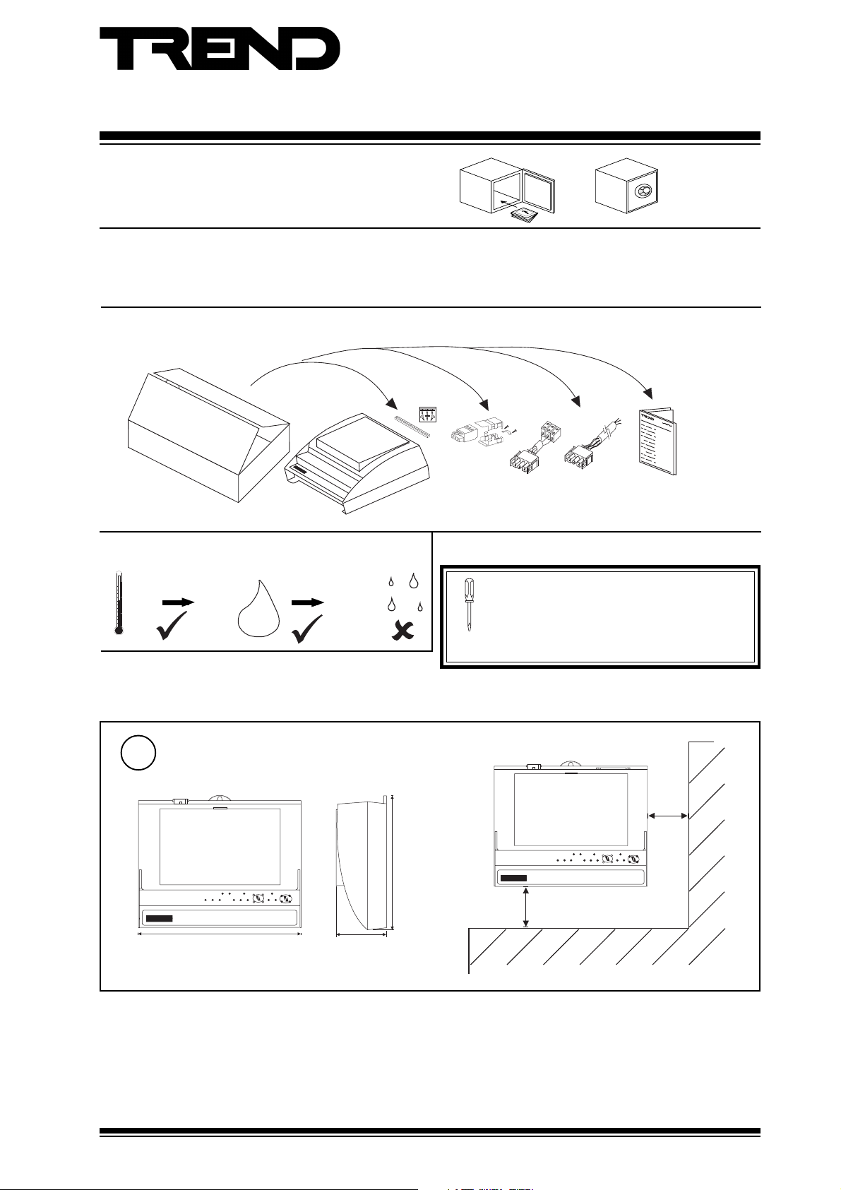
1 Unpacking
2 Storing
-10 °C
(14 °F)
+50 °C
(122°F)
H O
0
2
95 %RH
3 Installation........................................................................ 1
3.1 Installation - Mounting ..................................................... 1
3.2 Installation - Configuration.............................................. 5
4 Disposal......................................................................... 11
Installation
Instructions,
TG200220
../230 only
EJ105383
../24 only
It is recommended that the installation should
comply with the HSE Memorandum of Guidance
on Electricity at Work Regulations 1989.
For USA install equipment in accordance with
the National Electric Code.
../24/USA
only
3 Installation
3.1 Installation - Mounting
Dimensions
1
I N C 2
230 mm (9.05")
70 mm
(2.75")
181 mm (7.125")
50 mm
(2")
I N C 2
100 mm
(4")
NBOX(B)/INC2 Installation Instructions TG200220 Issue 1/E 22/11/06
1
Page 2
NBOX(B)/INC2 Installation Instructions
TX R X
LA N
LA N
1
2 3 4 5
6 7 8
9 101112
13
14
15
V
24 V
16
17
18
19
20
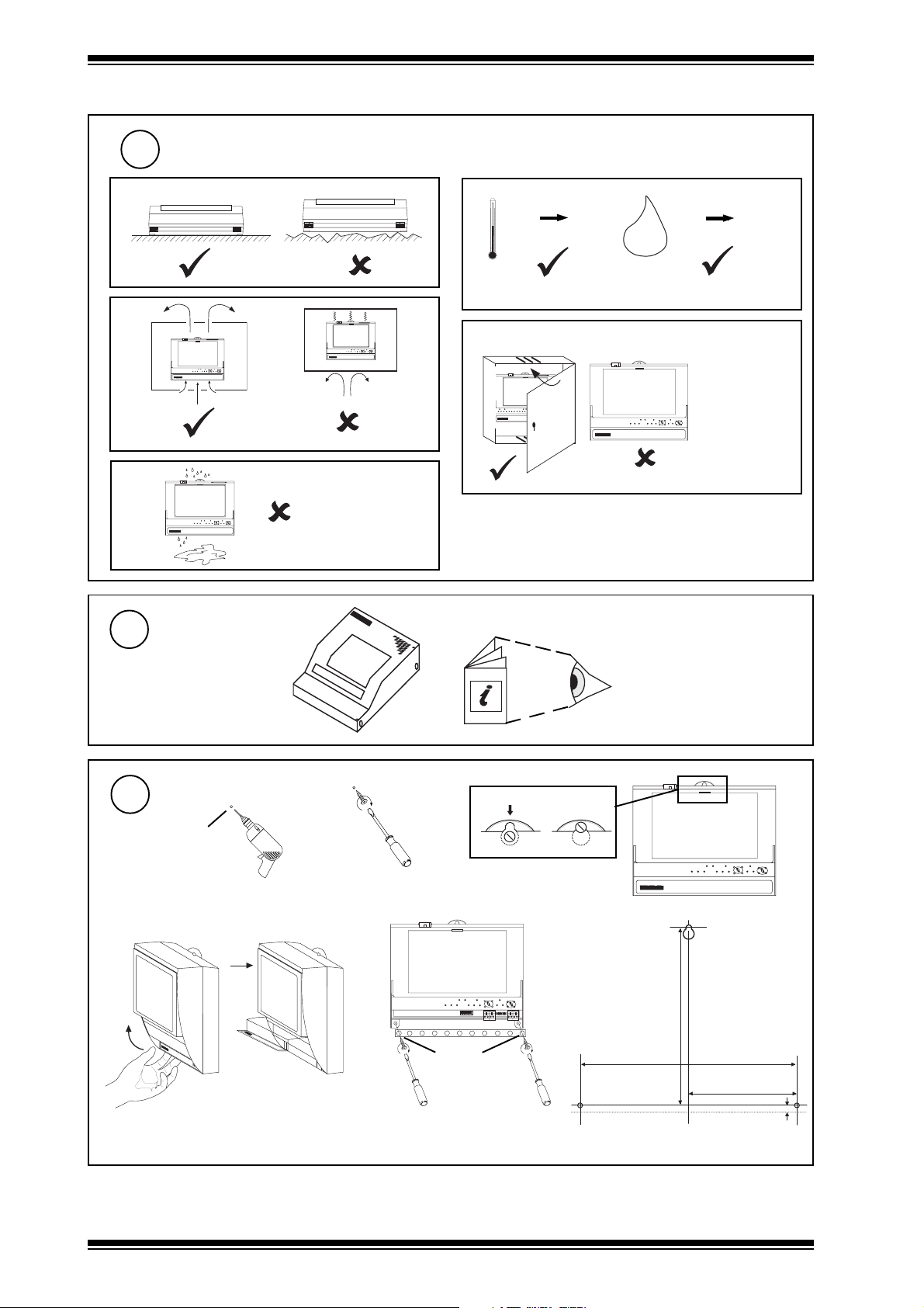
3.1 Installation - Mounting (Continued)
Requirements
2
a
b
c
3
IN C 2
IN C 2
Mount MBOX
d
0 °C
(32 °F)
+45 °C
(113 °F)
H O
2
0 %RH
95 %RH
Protection: IP30, NEMA1
e NBOX/INC2/USA only
IN C 2
The unit is UL
rate as 'UL916,
accessory to
open energy
management
I N C 2
equipment'
if using ENCLS/MBOX/IQ22x
Mounting
4
a
Ø 6 mm
(0.24")
e
ENCLS/MBOX/IQ22x
Installation Instructions
TG200203
b
c
d
I N C 2
f
172 mm (6.77")
Ø 6 mm
(0.24")
209 mm (8.23")
104.5 mm (4.11")
7 mm (0.28")
2
NBOX(B)/INC2 Installation Instructions TG200220 Issue 1/E 22/1 1/06
Page 3
Installation Instructions NBOX(B)/INC2
3.1 Installation - Mounting (Continued)
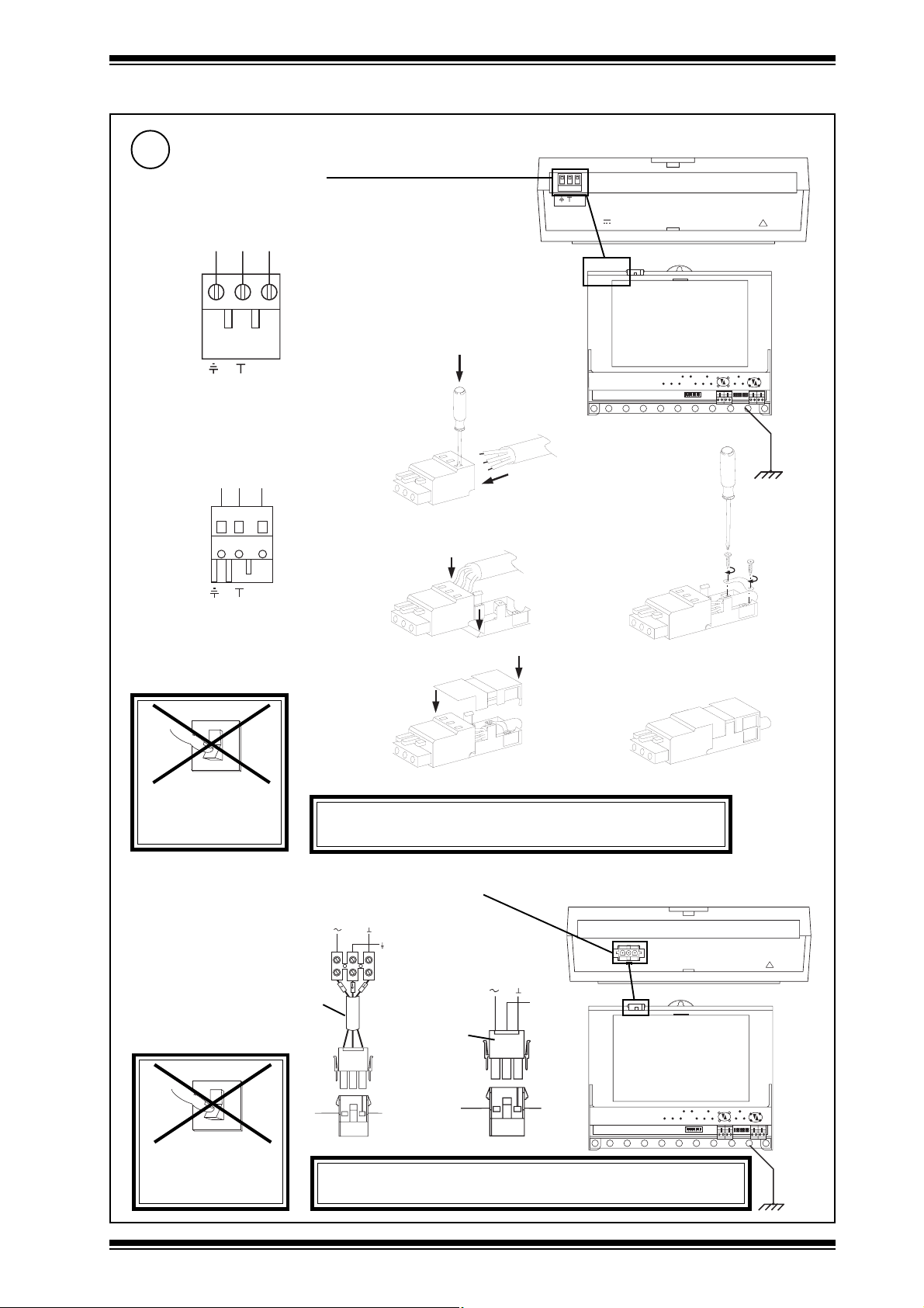
Connecting Power
5
/230 230 Vac
either screw terminal
E N L
~
E N L
Terminal size 0.5 to 2.5 mm
(14 to 20 AWG)
or shrouded plug kit
E N L
NBOX(B)/INC2/230 consumption < =7.5 VA
~
~
2 4 V
2
M O D E M
a
b
c
R D S /R S 2 3 2
!
Earth
(ground)
the bus
bar
~
E N L
O
I
DO NOT APPLY
POWER
Mat-N-Loc to terminal;
adaptor (supplied)
O
I
d
e
WARNING: This apparatus must be earthed (grounded).
(using input power earth (ground) terminal)
NBOX/INC2/24 consumption < =7.5 VA
24 V versions
+24V 0V
24 Vdc:
24 Vac:
24 Vac
EJ105383
0V
Earth
/USA only
+24V 0V
24 Vdc:
24 Vac
Yellow
Green
0V
Earth
Blue
24 Vac:
24V
2 part
2 4 V
Mat-N-Loc
connector
(supplied)
~
M O D E M
R D S /R S 2 3 2
!
DO NOT APPLY
POWER
NBOX(B)/INC2 Installation Instructions TG200220 Issue 1/E 22/1 1/06
WARNING: This apparatus must be earthed (grounded).
(using input power earth (ground) terminal)
Earth
(ground)
the bus
bar
3
Page 4
NBOX(B)/INC2 Installation Instructions
T
R
T
R
T
R
T
R
T
R
T
R
T
R
T
R
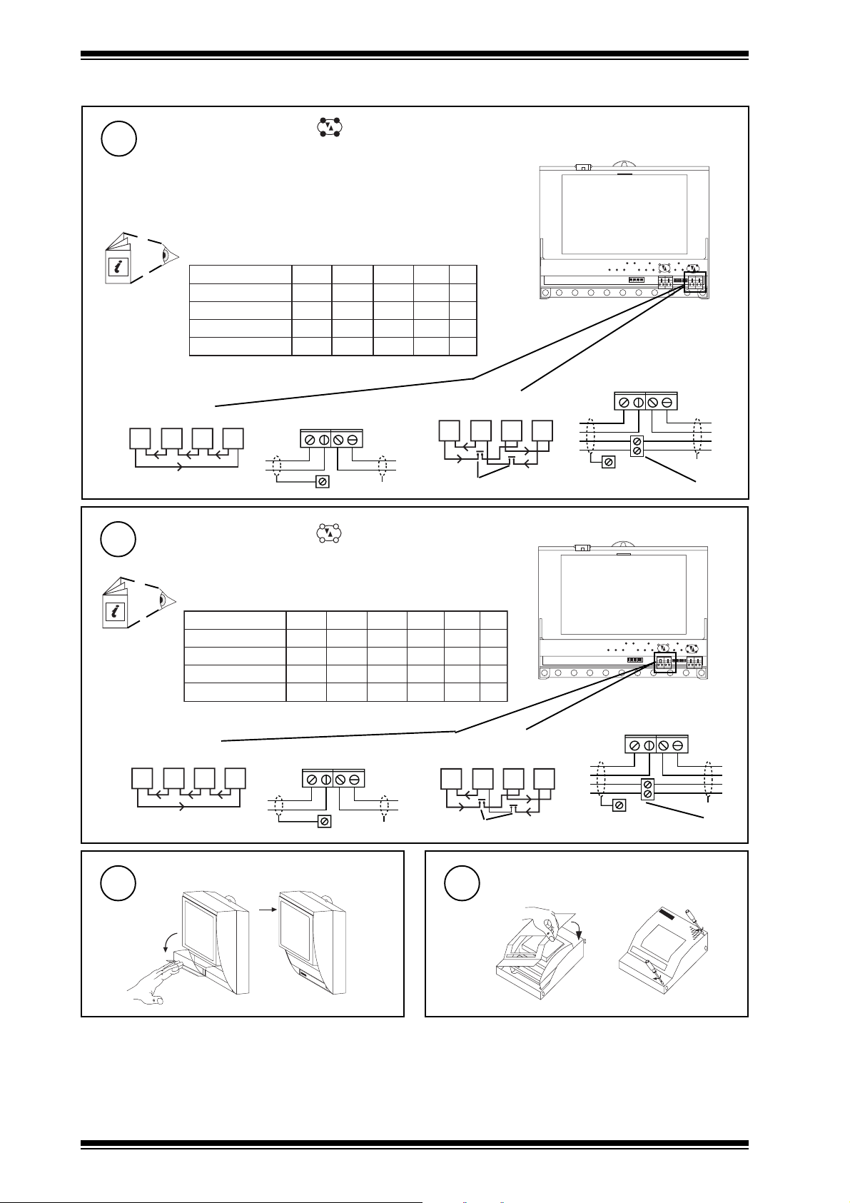
3.2 Installation - Mounting (continued)
Connect Network (Lan A)
6
(unless RS232 receiver/transmitter Device A being used e.g. leased line modem)
Normally Local Lan dumb/normal switch set to dumb, any address
dumb/normal switch set to normal, address <100
Note that EINCs, INCs LINCs cannot be on same local Lan
Internetwork segment A i f dumb/normal switch set to normal (internetwork
buffer), address >=100
Network Engineering Manual, 92-1735
2k91
elbaCduab2k1duab8k4duab6k9
2819nedleB
7029nedleB
)1678ned
leB(
)3278nedleB(
m0001
m0001
)sdy0901(
m0001
)sdy0901(
m0001
002/FH/22/1/1/PTmetysQI
002/FH/22/2/2/PTmetsysQI
)sdy0901(
m0001
)sd
y0901(
m0001
)sdy0901(
)sdy0901(
m0001
)sdy0901(
m0001
)sdy0901(
m0001
)sdy0901(
567(
m0001
)sdy0901(
m007
)sdy567(
m005
)sdy545(
fo.oN
duab
seriW
m007
2
)sdy
m005
2
)sdy545(
m053
2
)sdy083(
m052
4
)sdy072(
Polarity independent
Terminal size 0.5 to 2.55 m2 (14 to 20 AWG)
2 wire
R
R
LAN A
T-
T+
R+
R-
Earth
(ground)
bus
T R T R T R T R
T
T
X
additional terminals
Connect Network (Lan B)
7
(unless RS232 receiver/transmitter Device B being used e.g. leased line modem)
Always Internetwork
4 wire
LAN A
T-
R
R
T
T
T+
Earth (ground) bus
R+
R-
T
T
R
R
X
additional terminals
Network Engineering Manual, 92-1735
elbaCduab2k1duab8k4duab6k9
2819nedleB
7029nedleB
)1678nedleB(
)3278nedleB(
002/FH/22/1/1/PTmetsysQI
002/FH/22/2/2/PTmetsysQI
Polarity independent
Terminal size 0.5 to 2.55 m2 (14 to 20 AWG)
2 wire
LAN B IWRK
R
R
Close Flap
8
2k91
4k83
duab
m0001
m0001
)sdy0901(
m0001
m0001
m0001
)sdy0901(
m0001
)sdy0901(
)sdy0901(
m0001
)sdy0901(
)sdy0901(
m0001
)sdy0901(
)sdy0901(
m007
m0001
m0001
m007
m005
)sdy567(
)sdy0901(
m005
)sdy0901(
)sdy545(
m053
)sdy567(
)sdy083(
m052
)sdy545(
)sdy072(
fo.oN
duab
seriW
m005
2
)sdy545(
m053
2
)sdy083(
m052
2
)sdy072(
m521
4
)sdy531(
LAN B IWRK
4 wire
T-
R+
T+
R
T-
R+
T+
R-
Earth
(ground)
bus
T
T
X
T R T R T R T R
additional terminals
Close MBOX
R
T
T
Earth (ground) bus
if fitted in ENCLS/MBOX/IQ22x
R-
T
T
R
R
X
additional terminals
9
a
b
4
NBOX(B)/INC2 Installation Instructions TG200220 Issue 1/E 22/1 1/06
Page 5

Installation Instructions NBOX(B)/INC2
3.2 Installation Configuration
1
Switch off
Open Panel
2
NBOX/INC2/USA only
The unit is UL rated as 'UL916,
O
I
accessory to open energy
management equipment'
LA N
17
20
18
16
19
LA N
TX R X
V
24 V
1
6 7 8
9 101112
2 3 4 5
13
15
14
a
3
Open MBOX
if unit fitted in
ENCLS/MBOX/IQ22x
b
WARNING:
Opening the panel may expose
dangerous voltages. 417-IEC-5036
Open Flap
4
a
b
e.g.
Set Dumb/Normal switch
5
O N
A D D R E S S
D U M B
N O R M
Dumb
Sets INC mode only:
(Lan/Internetwork gateway, Lan A
always a Lan, never Internetwork)
Norm
Sets Internetwork extension or INC
mode dependent on address (see step
6 below)
Set the INC2 Internetwork Address
6
(Lan number)
e.g.
O N
A D D R E S S
Address = 2+16= 18
address
if dumb (traditional INC mode only)
address defines Lan number
on Internetwork
(Lan/Internetwork gateway)
if
normal
if address < 100, address defines
Lan number on Internetwork
(Lan/Internetwork gateway)
D U M B
N O R M
SET
NOT SET
1, 4 to 9, 11 to 114
0, 2, 3, 10 or >119
Address = D
Lan
= D
Lan
= D
/
Lan
= D
/
AB
Lan
NBOX(B)/INC2
Lan
= D
/
Inter-
INC2
network
Set Lan A Network Baud Rate
7
(or Device A RS232 baud rate if connected to RS232
receiver/transmitter)
Baud A
BAUD B BAUD A
BAUD A
e.g 9k6
move link to
set baud rate
Network Baud Rate = R1
(or RS232 to Device A)
= R1
= R1
= R1
= R1
if address = > 100, address is for
configuration only
(Internetwork extension
mode)
Inter-
network
Segment A
Inter-
AB
INC2
network
Segment B
NBOX(B)/INC2 Installation Instructions TG200220 Issue 1/E 22/1 1/06
BAUD B BAUD A
5
Page 6

NBOX(B)/INC2 Installation Instructions
3.2 Installation - Configuration (Continued)
Set Lan B Internetwork Baud Rate
8
(or Device B RS232 baud rate if connected to RS232 receiver/transmitter)
Baud B
e.g 19k2
BAUD B BAUD A
or High Baud Rate, 38k4
move link to
set baud rate
BAUD B
BAUD B BAUD A
Internetwork Baud Rate = R2
(or RS232 to Device B)
= R2
Note:
needs
= R2= R2
extra link
BAUD B BAUD A
= R2
Remove Cover
9
if Connecting to RS232 Receiver/Transmitter
a Switch off
O
I
Caution: This unit contains static sensitive devices. Suitable anti-static precautions should be taken throughout this
operation to prevent damage to the unit.
BS EN100015/1 Basic Specification: protection of electrostatic sensitive devices.
Connect to RS232 Device A
10
if Device A is a RS232 receiver/transmitter
(e.g. leased line modem)
Note: Connecting a cable to an RS232
connector disables corresponding Lan
ET 1
communications.
J1 6
D ev B
J1 5
J15
D ev A
Dev A
La n B La n A
J7
J1 3
J1 2
J9
CABLE/EJ100179A001
not supplied
Device A
Receiver/
Transmitter
b Remove Cover
11
J1 3
J1 2
Connect to RS232 Device B
if Device B is a RS232 receiver/transmitter
(e.g. leased line modem)
Note: Connecting a cable to an RS232
connector disables corresponding Lan
ET 1
communications.
J1 6
J16
D ev B
J1 5
Dev B/Modem
D ev A
La n B La n A
J7
J9
CABLE/EJ100179A001
not supplied
Device B
Receiver/
Transmitter
1
J15
10 Way, Female, Molex
links between pins 2-4, 3-5
6
Dev A
25 Way, Female,
'D type'
black sheath
1
J16
10 Way, Female, Molex
links between pins 2-4, 3-5
Dev B/
Modem
25 Way, Female,
'D type'
black sheath
NBOX(B)/INC2 Installation Instructions TG200220 Issue 1/E 22/1 1/06
Page 7

Installation Instructions NBOX(B)/INC2
O
I
3.2 Installation - Configuration (Continued)
12
14
Replace Cover
if RS232 receiver/transmitter connected
Set Battery Links On
if NBOX(B)
O N O N
13
15
J1 3
J1 2
Switch On
Close Flap
J 1 3
J 1 2
O F F O F F
Check Node Controller
16
a (power)
(green)
LEAVE POWERED FOR 16 HOURS
b (watchdog)
(red)
INC2 Faulty
Check input
power
NBOX(B)/INC2 Installation Instructions TG200220 Issue 1/E 22/1 1/06
7
Page 8

NBOX(B)/INC2 Installation Instructions
N B O X ( B ) / I N C 2
?
N B O X ( B ) / I N C 2
?
N B O X ( B ) / I N C 2
?
3.2 Installation - Configuration (Continued)
17
LAN A
T X - T X + R X - R X +
Check Lan A
Not if RS232 receiver/transmitter
connected to Dev A
OKA
INC2 Faulty
LAN A
T X - T X + R X - R X +
a RXA
(yellow)
b TXA
(yellow)
c OKA
(green)
✘
NBOX(B)/INC2
O
I
N B O X ( B ) / I N C 2
?
Network Address Invalid
0, 2, 3 or >119
OKA
Check network cabling
for short circuits with a
multimeter (NOT Megger)
Check baud rate . Power
up other nodes until faulty
node is found (OK ).
Correct fault.
18
LAN B
T X - T X + R X - R X +
Check Lan B
Not if RS232 receiver/transmitter
connected to Dev B
OKB
INC2 Faulty
LAN B
T X - T X + R X - R X +
a RXB
(yellow)
b TXB
(yellow)
c OKB
(green)
✘
NBOX(B)/INC2
O
I
Network Address Invalid
0, 2, 3 or >119
OKB
Check network cabling for
short circuits with a
multimeter (NOT Megger)
Check baud rate .Power
up other nodes until faulty
node is found (OK ).
Correct fault.
8
NBOX(B)/INC2 Installation Instructions TG200220 Issue 1/E 22/1 1/06
Page 9

Installation Instructions NBOX(B)/INC2
3.2 Installation - Configuration (Continued)
INC2
Network Engineering Manual 92-1735
IQ Configuration Manual 90-1533
19
Configure
INC2 Data Sheet TA200209
Use SET
Top Menu
Select from lanmap or set addresses as below:
• If on local Lan or autodialled Lan, set Lan = 0, address = 126.
Note address used for old INC, Lan 126, address 126, still works
•If using Internetwork or autodialled remote Lan, set Lan = switch
setting, address = 126
to eXit module having
changed parameter
Note that a PIN may be required to make changes in configuration mode. If the PIN has been forgotten the user should contact Trend Technical Support
quoting the generator number (User module) whereupon a default PIN will be supplied. This will only work during the same configuration mode session i.e.
the utility must not be exited between reading the generator and entering the default PIN. After the PIN is entered a new PIN should be set up and remembered.
X
INC2
User addRess
R
e.g.
to Quit module and
discard changes
select addRess module
Q
Settings that may be changed
20
Set up following parameters if required
retemaraPgnitteSnoitcnuFnoitidnoCetoN
smrala
noitareneg
lehtrofreifitnedIyalpsiD/srosivrepusroftessyawlA
)AnaL(na
smralaAnaLrof
gratmrala2CNIforebmunnaL
smralaAnaLrof
smralaBnaLrof
smralaBnaLrof
te
tegratmrala2CNIforebmunnaL
tenfoegaugnalstceleS
slenaP
tegratmrala2CNIfosserddaedon
tegratmrala2CNIfosserddaedon
degnahcebotegaugnalfI2
torpnu(knalbsitluafeD
.deriuqerytirucesfipu
eTotevig,ylnodaeR
NIPtluafed
sseRddareifitneDisretcarahcciremunahpla51
krowteNlacoL
otsmrala
krowtenretnI
otsmrala
resUniPrebmunnoitarugifnocnisegnahcstcetorP
sserddAot11,9ot4,1sserddaedon
ssErddaot11,9ot4,1sse
ePytegaugnalmrala
911
naletomeRot11,9ot4,1rebmunnaL
911
rddaedon
911
naL
naleTomerot11,9ot4,1rebmun
911
rotarenegrebmunNIPtluafedrofrebmunmodnar
sretcarahc*?;{(\/ton-
)stigid(9ot0krow
edom
Notes
1. If set to zero - no alarms reported
2. Language tyPe values:
0=English, 1=Spanish, 2=Finnish, 3=Swedish, 4=Norwegian, 5=Danish, 6=German, 7=Italian, 8=Portuguese, 9=French.
21
Exit Configuration
X
Æ "Exit from Utility"
detroperebotsmralaAnaLfI1
detroperebotsmralaAnaLfI1
detroperebotsmralaBnaLfI1
detroperebotsmralaBnaLfI1
teS.)detce
roferaCinhc
NBOX(B)/INC2 Installation Instructions TG200220 Issue 1/E 22/1 1/06
9
Page 10

NBOX(B)/INC2 Installation Instructions
3.2 Installation - Configuration (Continued)
Check INC2 Operation
22
If operating in INC mode
Lan/Internetwork Gateway (INC2 C or D)
If Internetwork extension mode (dumb/normal = normal
and address =>100)
Internetwork extension mode (INC2 E)
Lan
Close MBOX
23
if fitted in ENCLS/MBOX/IQ22x
a
C
Internetwork
b
INC2
C
Internetwork
Segment
A
Lan
IQINC2INC2
Lan
D
Close Panel
24
Internetwork
INC2 INC2
Segment
B
E
D
Lan
IQ
NBOX/INC2/USA only
LA N
17
20
18
16
19
LA N
TX RX
V
1
2 3 4 5
24 V
6 7 8
9 1 01112
13
15
14
The unit is UL rated as 'UL916,
accessory to open energy
management equipment'
10
NBOX(B)/INC2 Installation Instructions TG200220 Issue 1/E 22/1 1/06
Page 11

Installation Instructions NBOX(B)/INC2
4 Disposal
WEEE Directive :
At the end of their useful life the packaging,
and product should be disposed of by a suitable
Do not dispose of with normal household waste.
Do not burn.
recycling centre.
NBOX(B)/INC2 Installation Instructions TG200220 Issue 1/E 22/1 1/06
11
Page 12

NBOX(B)/INC2 Installation Instructions
This page is intentionally left blank
Manufactured for and on behalf of the Environmental and Combustion Controls Division of Honeywell Technologies Sàrl, Ecublens, Route
du Bois 37,Switzerland by its Authorized Representative, Trend Control Systems Limited.
Trend Control Systems Limited reserves the right to revise this publication from time to time and make changes to the content
hereof without obligation to notify any person of such revisions or changes.
Trend Control Systems Limited
P.O. Box 34, Horsham, West Sussex, RH12 2YF, UK. Tel:+44 (0)1403 211888 Fax:+44 (0)1403 241608 www.trend-controls.com
Trend Control Systems USA
6670 185th Avenue NE, Redmond, Washington 98052, USA. Tel: (425)897-3900, Fax: (425)869-8445 www.trend-controls.com
12
NBOX(B)/INC2 Installation Instructions TG200220 Issue 1/E 22/1 1/06
 Loading...