

Page 1
Installation Instructions - Sheet 1
TX R X
OK
DT RB
DT RA
CT SBCT SA
NBOX(B)/CNC2
Communication Node Controller
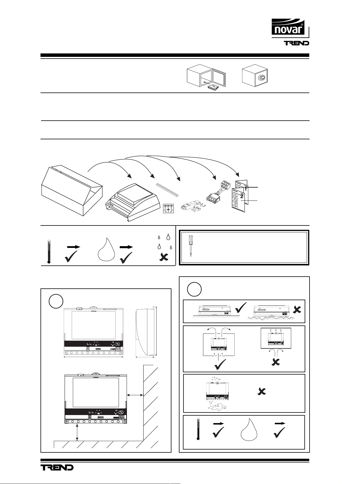
Important: Retain these instructions
CONTENTS
1.1 Unpacking 1 - 1
SHEET 1: Installation Intructions - Fixing
1.1 Unpacking
1.2 Storing
-10 °C
+50 °C
H O
0
2
95 %RH
1.2 Storage 1 - 1
1.3 Installation Instructions - Fixing 1 - 1
2. Installation Instructions - Configuration 2 - 1
1
Installation Instructions,
TG200265
Sheet 1, Fixing
Sheet 2, Configuring
../24 only
../230 only
It is recommended that the installation should
comply with the HSE Memorandum of Guidance
on Electricity at Work Regulations 1989.
1.3 Installation -Fixing
Dimensions
1
D T R B
D T R A
C T S BC T S A
D T R B
D T R A
C T S BC T S A
100 mm
Requirements
2
a
!
b
O K
T X R X
70 mm230 mm
181 mm
c
50 mm
O K
T X R X
d
0 °C
Protection : IP30
24 V
RD S /R S2 32
MO D EM
DT R A
~
DT R B
CT S BCT S A
~
23 0V
OK
TX RX
+45 °C
H O
!
RD S /R S 23 2
0 %RH
2
24 V
M OD E M
~
~
23 0V
OK
DT RB
DT RA
TX R X
CT SBCT SA
95 %RH
NBOX(B)/CNC2 Communications Node Controller Installation Instructions TG200265 Issue 1/B 20/07/04
1 - 1
Page 2
NBOX(B)/CNC2 Installation Instructions - Sheet 1
T X R X
O K
D T R B
D T R A
C T S BC T S A
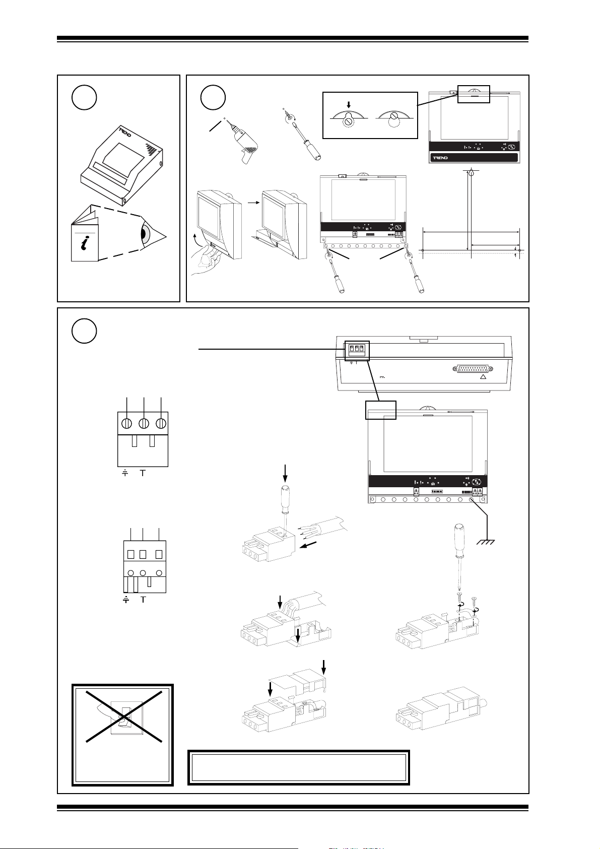
1.3 Installation - Fixing (continued)
Mount MBOX
3 4
if using ENCLS/MBOX/IQ22x
ENCLS/MBOX/IQ22x
Installation Instructions
TG200203
Connecting Power
5
/230 230 Vac
either screw terminal
E N L
Mounting
Ø 6 mm
a
b
c
d
ef
O K
D T R B
D T R A
T X RX
C T S BC T S A
Ø 6 mm
NBOX(B)/CNC2/230 consumption < =7.5 VA
2 3 0 V
~
~
2 4 V
209 mm (8.23")
M O D E M
D T R A
C T S A
(6.77")
172 mm
R D S /R S 2 3 2
O K
D T R B
T X RX
C T S B
104.5 mm
(4.11")
7 mm
(0.28")
!
C N C 2
E N L
~
or shrouded plug kit
E N L
E N L
terminal size 0.5 to 2.5 mm
DO NOT APPLY
POWER
~
0
I
a
b
2
d
WARNING: This apparatus must be earthed.
(via mains earth terminal)
Earth the
bus bar
c
e
1 - 2
NBOX(B)/CNC2 Communications Node Controller Installation Instructions TG200265 Issue 1/B 20/
07/04
Page 3
Installation Instructions - Sheet 1 NBOX(B)/CNC2
TX RX
OK
DTRB
D T R A
CTSBCTSA
1.3 Installation - Fixing (continued)
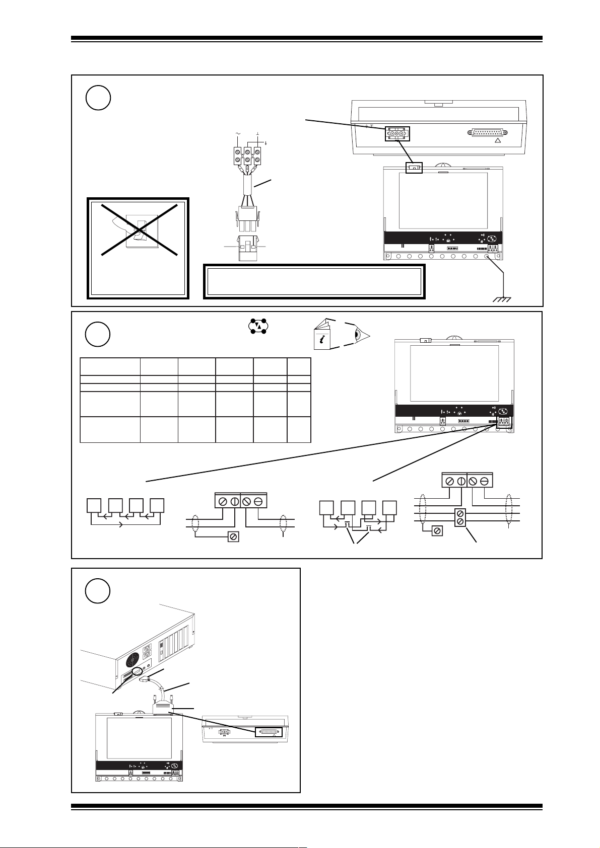
Connecting Power (continued)
5
/24 24 Vac or 24 Vdc
0
I
DO NOT APPLY
POWER
Connect Trend Lan (Lan A)
6
elbaCduab2k1duab8k4duab6k9
2819nedleBm0001m0001m0001m0072
7029nedleBm0001m0001m0001m0052
metsysQI
2/FH/22/1/1/PT
)1678nedleB(
metsysQI
)3278nedleB(
terminal size 0.5 to 2.5 mm
Network Engineering Manual, 92-1735.
00
002/FH/22/2/2/PT
m0001m0001m007m0532
m0001m0001m005m0524
24 Vdc:
24 Vac:
WARNING: This apparatus must be earthed.
Polarity independent
2
24 V versions
+24V 0V
24 Vac
0V
Earth
Mat-N-Loc to terminal
24V
adaptor (supplied)
EJ105383
(via green earth wire)
2k91
duab
NBOX/CNC2/24 consumption < =7.5 VA
2 3 0 V
~
~
2 4 V
fo.oN
seriW
M O D E M
D T R A
DTRB
CTSBCTSA
L A N A
R D S /R S 2 3 2
OK
TX RX
!
Earth the
bus bar
2 wire
T
T
R
R
T
R
T
R
Connect to Local Device
7
(RS232 Port)
e.g PC
9 Way D type, Female
PC's COM port
O K
D T R B
D T R A
T X R X
C T S BC T S A
L A N A
T -
T + R -
R +
R
R
e a r t h b u s
cable not supplied with unit
CABLE/58-0750
25 Way D type, Male
23 0 V
~
~
M O D E M
24 V
4 wire
R
R
T
R
R
T
T
T
T
X
R D S /R S 2 3 2
!
additional terminals
R
R
T
T
T
T -
e a r t h b u s
R +
T + R -
additional terminals
T
T
R
R
X
NBOX(B)/CNC2 Communications Node Controller Installation Instructions TG200265 Issue 1/B 20/07/04
1 - 3
Page 4

NBOX(B)/CNC2 Installation Instructions - Sheet 1
1.3 Installation - Fixing (continued)
Connect Auxiliary Supply Output
8
24 V
AUX
e.g. NDP
CNC2
D T R A
DTRB
CTSBCTSA
terminal size 0.5 to 2.5 mm
Close Flap
9
Configure/Commission
11
OK
TX RX
2
CNC2
24 V
I max = 150
mA
NDP
Close MBOX
10
a
if fitted in ENCLS/MBOX/IQ22x
b
2
NBOX(B)/CNC2 Installation Instructions
- Sheet 2: Configuration.
1 - 4
NBOX(B)/CNC2 Communications Node Controller Installation Instructions TG200265 Issue 1/B 20/
07/04
Page 5

Installation Instructions - Sheet 2
A D D R E S S
O N
D U M B
N O R M
NBOX(B)/CNC2
Communication Node Controller
SHEET 2: Installation Instructions - Configuration
Fix Unit
1
NBOX/CNC2 Installation
Instructions - Sheet 1: Fixing
1
Open Flap
4
a
b
2
Switch off
O
I
5
e.g.
Open MBOX
3
if unit fitted in ENCLS/MBOX/IQ22x
a
2
Set the Network Address
(Lan A)
Address = 2+16+64= 82
SET
NOT SET
b
D T R A
DTRB
CTSBCTSA
Address = D
= D
= D
/
OK
TX RX
NBOX(B)/CNC2
= D
/
Set Network Baud Rate
6
(Baud A)
Baud B Baud A
move link to
set baud rate
e.g 9k6
Baud B Baud A
D T R A
Network Baud Rate = R1
= R1
= R1
= R1
OK
DTRB
TX RX
CTSBCTSA
= R1
address
1, 4 to 9, 11 to 114
0, 2, 3, 10 or >119
Set RS232 Port to Local Device Baud
7
Rate
(Baud B)
Baud B Baud A
RS232 Port Baud Rate = R2
move link to
set baud rate
e.g 19k2
Baud B Baud A
= D
/
= R2
D T R A
= R2
DTRB
CTSBCTSA
CNC2
OK
TX RX
NBOX(B)/CNC2 Communications Node Controller Installation Instructions TG200265 Issue 1/B 20/07/04
2 - 1
Page 6

NBOX(B)/CNC2 Installation Instructions - Sheet 2
O
I
TX RX
OK
DTRB
D T R A
CTSBCTSA
Installation - Configuration (continued)
8
10
a
Switch On
Close flap
Set Battery Links On
9
if NBOXB
ON
ON
0
J 1 3
I
OFF
J 1 3
OFF
D T R A
OK
DTRB
TX RX
CTSBCTSA
Note: Batteries must be charged for
16 hours before they will support
unit during mains failure
Check Node Controller
11
b
a (power)
(green)
Check supply
12
L A N A
T - T + R - R +
Check Network
(Lan A)
D T R A
DTRB
CTSBCTSA
OK
CNC2 faulty
TX RX
OK
L A N A
T - T + R - R +
b (watchdog)
(red)
aRX
(yellow)
bTX
(yellow)
c OK
(green)
CNC2 Faulty
✘
NBOX(B)/CNC2
NBOX(B)/CNC2
?
NBOX(B)/CNC2
?
Network Address invalid
0, 2, 3 or >119
OK
Check network cabling for
short circuits with a
multimeter (NOT Megger)
Check baud rate
Power up other nodes until
faulty node is found
(OK ). Correct fault.
2 - 2
NBOX(B)/CNC2 Communications Node Controller Installation Instructions TG200265 Issue 1/B 20/07/04
Page 7

Installation Instructions - Sheet 2 NBOX(B)/CNC2
Installation - Configuration (continued)
Check System
13
T=X °C
CNC2
T=X °C
14
ab
Close MBOX
if fitted in ENCLS/MBOX/IQ22x
Lan A
temperature ?
IQ
NBOX(B)/CNC2 Communications Node Controller Installation Instructions TG200265 Issue 1/B 20/07/04
2 - 3
Page 8

NBOX(B)/CNC2 Installation Instructions - Sheet 2
This page is intentionally left blank
Trend Control Systems Ltd reserves the right to revise this publication from time to time and make changes to the content hereof
without obligation to notify any person of such revisions or changes.
Website www.trend-controls.com
Fax (UK) +44 (0)1403 241608
E-mail trendinfo@novar.com
2 - 4
P.O. Box 34, Horsham, West Sussex, RH12 2YF United Kingdom
Telephone +44 (0)1403 211888
Registered office. Novar House 24 Queens Road Weybridge Surrey KT13 9UX Registered in England No 1664519
Fax (International) +44 (0)1403 210982
NBOX(B)/CNC2 Communications Node Controller Installation Instructions TG200265 Issue 1/B 20/07/04
 Loading...