

Page 1
Outside Light Level Sensor
Important: Retain these instructions
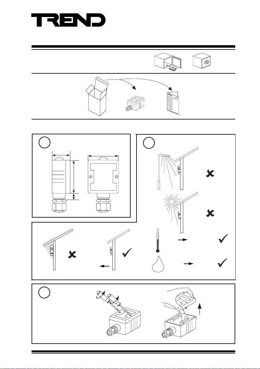
UNPACKING
Installation
Installation Instructions
LLO
LLO Installation
Instructions
TG100153A
Dimensions
1
36 mm (1.42”)
cd
Remove Lid
3
undo 2 screws
60 mm (2.4”)
65 mm (2.16”)
10 mm
(0.4”)
N
(north)
Requirements
2
a
b
e
-25 °C
-13 °F
0 %RH
H O
2
Protection :IP65 (NEMA 4)
+70 °C
+158 °F
95 %RH
LLO Installation Instructions TG100153A Issue 3/B 10/04/06
1
Page 2
LLO Installation Instructions
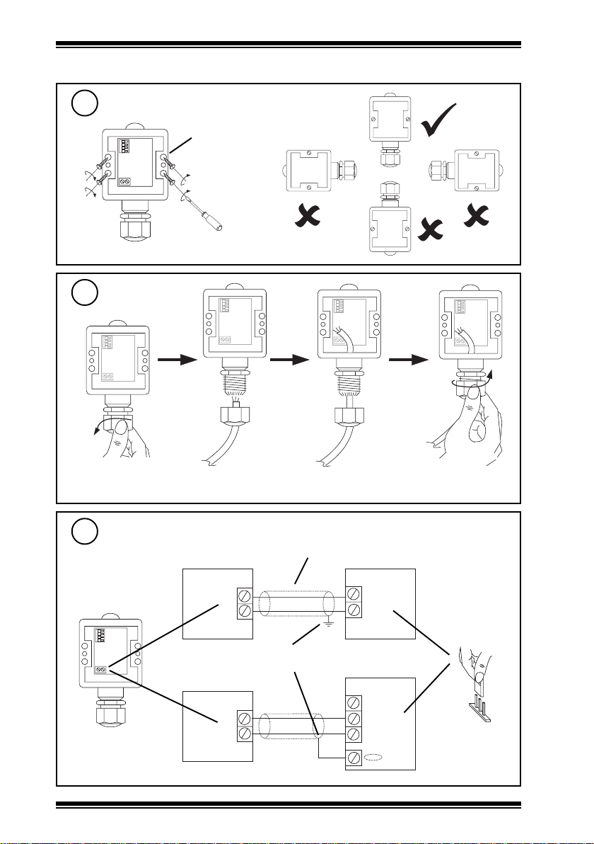
Installation (continued)
Mount on Wall
4
4 off Ø 3.5 mm
fix using 2
screws
minimum
Insert Cable
5
Note that IP65 rating is only achieved if the sensor is correctly installed with cable gland fully
tightened.
Wire to Controller
6
Cable 1.5 mm2 cross-sectional area (16 AWG) maximum
Sensor
+
-
-
+
2
Sensor, although
marked, is polarity
independent
Sensor
Terminate screen at
IQ end only
+
-
LLO Installation Instructions TG100153A Issue 3/B 10/04/06
IQ1 or IQ2
24 Vdc
IN
IQ3
0 (0 V)
N (in)
+ (24 V)
Analogue input
channel linked
for current (I)
I
Page 3

Installation Instructions LLO
Installation (continued)
Set up Range
7
(if required to change from range supplied)
1ws2ws3ws4ws)xul(egnaR
nOnOnOnO0001
-
+
8
e.g. Range 20000 lux (/20K)
Replace Lid
ffOnOnOnO0002
ffOffOnOnO0004
ffOffOffOnO0008
ffOffOffOffO00002
tighten 2 screws
Configure IQ
9
or
I Q
LLO Installation Instructions TG100153A Issue 3/B 10/04/06
I Q
IQ Configuration
Manual 90-1533
3
Page 4

LLO Installation Instructions
Installation
10
11
(continued)
Set up IQ Sensor types
It is recommended to use SET (Software Tool) for the setting of the sensor type module.
For all IQ2 series controllers with firmware verision 2.1 or greater, or IQ3 series
controllers, the following SET Unique Sensor References should be used:
2k Light I (2000 lux)
4k Light I (4000 lux)
20k Light I (20000 lux)
Alternatively (or for other ranges) enter scaling manually as defined in the table below.
For all other IQ controllers see Sensor Scaling Reference Card TB100521A.
tYpe Sensor digI/P Driver Function loGic Loop scHedule seQnc Analog
digBit Knob sWitch Time Zone Oss User addRess intcoN calarM reView Plot
calEndar
Yx<CR>
TYPE x
:
=?
S=5 (characterise)
Y=, E=, U=, L=, I1=, I2=, O1=, O2=
X <CR>
Test System
= ?
)xul(egnaR000100020004000800002
Y
E
U
L
P
x
1
2
epyttupni)tnerruc(2
tnenopxE 44555
reppU000100020004000800002
rewoL 00000
stnioP2
xIxO
4 00000
0200010
0020004000800002
Δ L
Note typical values:
15 to 20 lux dusk
IQ
2000 lux reasonable daylight
20000+ lux bright sunlight
(>20000 saturates sensor)
Disposal
WEEE Directive :
At the end of their useful life the packaging
and product should be disposed of via a
Do not dispose of with normal household waste.
Do not burn.
Manufactured for and on behalf of the Environmental and Combustion Controls Division of Honeywell Technologies Sàrl, Ecublens, Route
du Bois 37,Switzerland by its Authorized Representative, Trend Control Systems Limited.
Trend Control Systems Limited reserves the right to revise this publication from time to time and make changes to the content hereof
without obligation to notify any person of such revisions or changes.
Trend Control Systems Limited
P.O. Box 34, Horsham, West Sussex, RH12 2YF, UK. Tel:+44 (0)1403 21888 Fax:+44 (0)1403 241608 www.trend-controls.com
Trend Control Systems USA
6670 185th Avenue NE, Redmond, Washington 98052, USA. Tel: (425)869-8400, Fax: (425)869-8445 www.trend-controls.com
4
suitable recycling centre.
LLO Installation Instructions TG100153A Issue 3/B 10/04/06
 Loading...