

Page 1
Lon Internetwork Node Controller
!
Booklet on A3
if printing multiple copies ensure 'collate' checked
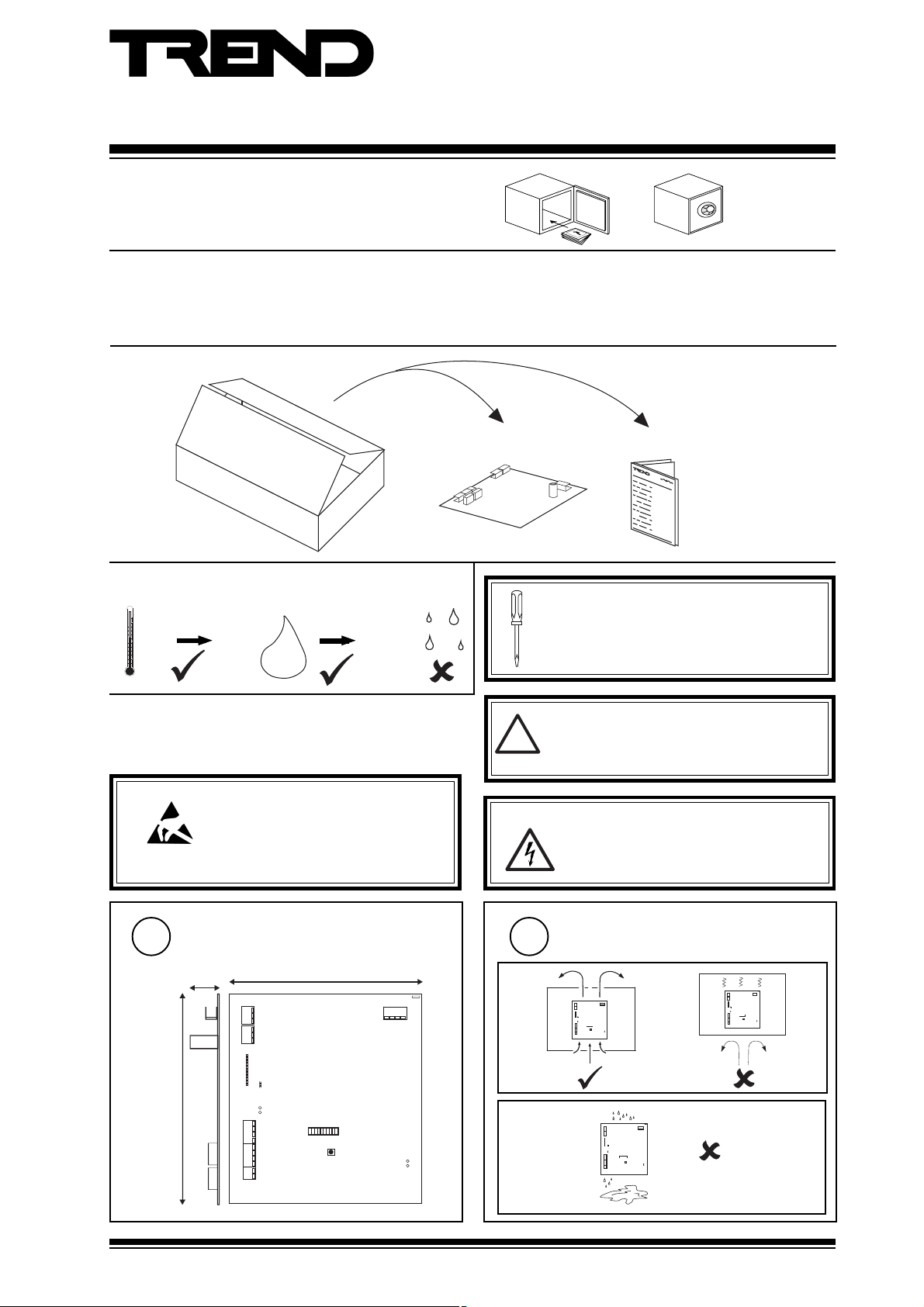
Important: Retain these instructions
Installation Instructions
LINC
CONTENTS
1 Unpacking .......................................................................... 1
2 Storage............................................................................... 1
1 UNPACKING
2 STORING
-10 °C
(14 °F)
+50 °C
(122 °F)
H O
0
2
95 %RH
3 INSTALLATION
3.1 Installation - Mounting
3 Installation......................................................................... 1
3.1 Installation - Mounting ....................................................... 1
3.2 Installation - Configuration ................................................ 5
4 Disposal ............................................................................. 8
LINC Installation
Instructions, TG103062
It is recommended that the installation should
comply with the HSE Memorandum of Guidance
on Electricity at Work Regulations 1989.
For USA install equipment in accordance with
the National Electric Code.
Note that this product may involve LonWorks
system integration as referred to in section 3.2 step
14: this procedure should only be performed by an
installer with LonWorks engineering expertise.
Caution: The LINC contains static sensitive devices.
Suitable anti-static precautions shoud be
taken throughout this operation to prevent
damage to the unit.
BS EN100015/1 Basic Specification: protection of
electrostatic sensitive devices.
Dimensions
1
35 mm
(1.38")
175 mm (6.89")
J15
J11
J4
J14
TX
RX
J12
J9
J17
160 mm (6.3")
ADDRESS
BAUD
19k2
9K6
1K2
163264
124
8
S3
SERVICE
LON OK
LAN OK
J1
D2
D3
Warning: Opening the panel may expose
dangerous voltages.
417-IEC-5036
Requirements
2
a
J1
J15
J11
J1
J15
J11
J4
J14
TX
RX
ADDRESS
BAUD
19k2
9K6
1K2
163264
J12
124
8
S3
J9
SERVICE
LON OK
D2
LAN OK
D3
J17
b
J1
J15
J11
J4
J14
TX
RX
ADDRESS
BAUD
19k2
9K6
1K2
163264
J12
124
8
S3
J9
SERVICE
LON OK
D2
LAN OK
D3
J17
J4
J14
TX
RX
BAUD
ADDRESS
19k2
9K6
1K2
163264
J12
124
8
S3
J9
SERVICE
LON OK
D2
LAN OK
D3
J17
LINC Installation Instructions TG103062 Issue 2/C 21/11/06
1
Page 2
LINC Installation Instructions
J15
J11
J4
J14
J12
J9
J17
SERVICE
S3
J1
TX
RX
LON OK
LAN OK
D2
D3
124
8
163264
19k2
9K6
1K2
BAUD
ADDRESS
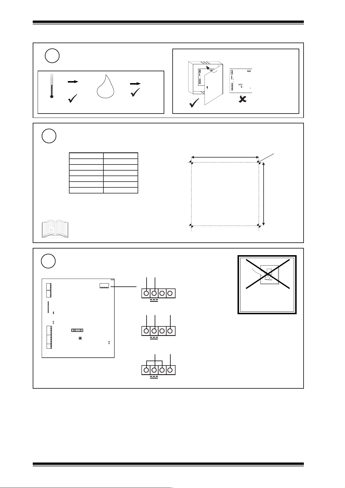
3.1 Installation - Mounting (Continued)
Requirements (Continued)
2
d
c
0 °C
(32 °F)
+45 °C
(113 °F)
H O
2
0 %RH
90 %RH
Protection: IP30
Mount the Node
3
The LINC can be fitted into enclosures and controllers as shown in the table below:
BBTEN/BTEN
+201/+101QI
+111QI
+131QI
x52QI
242/142QI
x32QI
* LINC board fits with 3 screws in normal node position or
fits in NDP position (if no NDP). Must use NDP position if
RDS fitted.
See appropriate enclosure/controller
installation instructions for more details about
node installation.
9
9
9
9
9*
9
9
J15
J11
J4
J14
TX
RX
J12
J9
J17
151 mm (5.94")
This unit is UL
J1
rated as 'UL916
ADDRESS
BAUD
19k2
9K6
1K2
163264
8
SERVICE
accessory to open
124
S3
energy
LON OK
D2
LAN OK
D3
management
equipment.'
4 off 4 mm
(0.157")
141 mm (5.55")
Connect Power LINC consumption < =6 VA
4
0V +24V
LON OK
LAN OK
J1
24 Vdc
~
~
0V
018
18
18-0-18 Vac
D2
D3
0V
~
~
18 Vac
J15
J11
J4
J14
TX
RX
J12
J9
J17
ADDRESS
BAUD
19k2
9K6
1K2
163264
124
8
S3
SERVICE
18 Vac (isolated)
~
~
0V
O
I
DO NOT SWITCH
ON
2
LINC Installation Instructions TG103062 Issue 2/C 21/11/06
Page 3

Installation Instructions LINC
J15
J11
J4
J14
J12
J9
J17
SERVICE
S3
J1
TX
RX
LON OK
LAN OK
D2
D3
124
8
163264
19k2
9K6
1K2
BAUD
ADDRESS
X
3.1 Installation - Mounting (Continued)
Connect Earth (Ground)
5
Connect Current Loop Network
6
Normally Local Lan address <100
Note that 3xtend/EINC Ls, EINCs, INCs, LINCs cannot be on same local Lan
Internetwork segment A if address >=100
elbaCduab2k1duab8k4duab6k9
2819nedleB
7029nedleB
)1678ned
leB(
)3278nedleB(
002/FH/22/1/1/PTmetysQI
m0001
m0001
m0001
m0001
002/FH/22/2/2/PTmetsysQI
y0901(
m0001
)sdy0901(
)sdy0901(
)sdy0901(
)sd
)sdy0901(
m0001
)sdy0901(
m0001
)sdy0901(
m0001
)sdy0901(
Terminal size 0.5 to 2.55 m2 (14 to 20 AWG)
Polarity independent
2 wire
T
R
T
R
R
R
LON OK
LAN OK
J1
D2
D3
J15
J11
J4
J14
TX
RX
J12
J9
J17
ADDRESS
BAUD
19k2
9K6
1K2
163264
124
8
S3
SERVICE
WARNING: This apparatus must be earthed
(grounded) using earth (ground) tag.
Note that the earth (ground) tag is internally connected to 0V
Network
Engineering
Manual,
92-1735
2k91
fo.oN
duab
m0001
)sdy0901(
567(
m0001
)sdy0901(
m007
)sdy567(
m005
)sdy545(
seriW
m007
2
)sdy
m005
2
)sdy545(
m053
2
)sdy083(
m052
4
)sdy072(
T
R
T
4 wire
TT
RR
R
T
R
T
R
T
R
T
R
TT+
RR+
TT+
internal links
RR+
X
T
T
LINC Installation Instructions TG103062 Issue 2/C 21/11/06
SCN
SCN
T
R
T
R
TT+
internal links
R-
R+
T
R
T
R
T
R
T
R
TT+
RR+
SCN
SCN
RR
TT
3
Page 4

LINC Installation Instructions
J15
J11
J4
J14
J12
J9
J17
SERVICE
S3
J1
TX
RX
LON OK
LAN OK
D2
D3
124
8
163264
19k2
9K6
1K2
BAUD
ADDRESS
3.1 Installation - Mounting (Continued)
Connect LonWorks
7
elbaChtgnelsubxaMedonotedonxaM
20158nedleBm005m005
dnerT
002/FH/61/0/1/PT
)1748nedleB(
GWA22,VIleveLLUm0
8.0x2x2Y)tS(YJm005m023
GWA42,5.taCA865AITm054m052
Normal current loop Lan cable is not recommended.
Do not use screened cable.
Terminal size 0.5 to 2.55 m2 (14 to 20 AWG)
If used with LPT-10 (powered bus), cable
lengths differ - see "Link Power Transceiver
User's Guide" (078-0105-01C)".
LonWorks - FTT (free topology)
*
T e r m in a t o r
*
T e r m in a t o r
m005m004
05m004
*
T e r m in a t o r
LonWorks
internal links
SCN
LonA
LonB
SCN
LonA
LonB
Do not allow wires to
cross on a loop
Close Panel
8
J15
J11
J4
J14
TX
RX
BAUD
9K6
1K2
J12
J9
J17
Star topology Bus topologyLoop topology
polarity independent
LonWorks
*Terminate LonWorks bus at one end only using IQLROUTER integrated LonWorks terminator
or LONTERMINATOR
LONTERMINATOR
100 mF, 50 V min
SCN
LINC
LonA
LonB LonA
SCN
Recommend terminate at
LINC or Router.
e.g. use IQLRouter integral
terminators
100 mF, 50 V min
J1
ADDRESS
19k2
163264
124
8
S3
SERVICE
LON OK
D2
LAN OK
D3
This unit is UL
rated as 'UL916
accessory to open
energy
LonB
IQLROUTER
A
6
45
7
89
IQL
T
B
10
11
y
z
x
w
SCN
LonA
Maximum 64 nodes per LonWorks segment
Maximum 40 IQLs (and LONCs) per Lan
IQLROUTER
T
A
6
45
7
89
IQL
T
B
10
11
xyzw
SCN
LonA
LONC
LonB LonA
SCN
LONC
LonB LonA
SCN
LonB
LonB
management
equipment.'
LINC Installation Instructions TG103062 Issue 2/C 21/11/06
4
Page 5

Installation Instructions LINC
ON
3.2 Installation - Configuration
Switch off
1
Set LINC Internetwork Address (Lan number)
3
ON
BAUD
1K2
9K6
19K2
64
e.g.
Address = 2 + 16 = 18
O
I
ADDRESS
16
32
Open Panel
2
WARNING: Opening the panel may expose
dangerous voltages.
417-IEC-5036
J15
J11
J4
J12
J9
J17
J1
J14
TX
RX
ADDRESS
BAUD
19k2
9K6
1K2
163264
124
8
S3
SERVICE
LON OK
D2
LAN OK
D3
Caution: This LINC contains static sensitive
devices. Suitable anti-static precautions
should be taken throughout this operation
to prevent damage to the unit.
BS EN100015/1 Basic Specification: protection of
electrostatic sensitive devices
Lan
= D
LON OK
LAN OK
J1
D2
D3
LINC
J15
J11
J4
J14
TX
RX
ADDRESS
BAUD
19k2
9K6
1K2
J12
J9
J17
4
2
1
SET
Address = D
163264
124
8
S3
SERVICE
NOT SET
Lan
= D
/
Lan
= D
/
address
1, 4 to 9, 11 to 119
0, 2, 3, 10 or >119
if address < 100, address defines Lan number on Internetwork (LonWorks internetwork)
if address = > 100, address is for configuration only (Internetwork LonWorks Extension)
Lan
Inter-
network
Segment A
Lan
= D
/
Internetwork on LonWorks
LINC
Internetwork Segment B
LINC
on LonWorks
LINC Installation Instructions TG103062 Issue 2/C 21/11/06
5
Page 6

LINC Installation Instructions
J15
J11
J4
J14
J12
J9
J17
SERVICE
S3
J1
TX
RX
LON OK
LAN OK
D2
D3
124
8
163264
19k2
9K6
1K2
BAUD
ADDRESS
ON
J15
J11
J4
J14
J12
J9
J17
SERVICE
S3
J1
TX
RX
LON OK
LAN OK
D2
D3
124
8
163264
19k2
9K6
1K2
BAUD
ADDRESS
O
I
3.2 Installation - Configuration (Continued)
Set Network Baud Rate
4
ON
5
BAUD
1K2
19K2
9K6
64
= 19k2 baud
= 9k6 baud
= 1k2 baud
Switch On
O
I
ADDRESS
16
32
Baud = C
Lan
LINC
=C
=C
Internetwork on LonWorks
LINC
4
2
1
SET
NOT SET
=C
=C
If address < 100,
baud rate of current loop Lan
If address = > 100,
baud rate of current loop Internetwork
Inter-
network
Segment A
Internetwork Segment B
LINC
on LonWorks
(Segment A)
Check Current Loop Network
6
If address < 100, current loop Lan
If address = > 100, current loop Internetwork (Segment A)
Lan OK (green)
NETB/LINC
Lan OK
Lan OK
Check network
cabling for short
circuits with a
multimeter (NOT
LINC Faulty
Megger)
Check baud rate.
Power up other nodes
X
until faulty node is
found (OK ).
Correct fault.
Check LINC on LonWorks
7
Lan
LINC
6
LINC
and
LONC
or
IQL
or
LonWorks
Lon OK (green)
Flashes every 24 s, ON after 1½ mins
(Check LonWorks, LINC, and LINC, or
LONC, or IQL)
J15
J11
J4
J14
TX
RX
ADDRESS
BAUD
19k2
9K6
1K2
163264
J12
8
J9
J17
LINC Installation Instructions TG103062 Issue 2/C 21/11/06
J1
124
S3
SERVICE
LON OK
D2
LAN OK
D3
Close Panel
8
J1
J15
J11
J4
J14
TX
RX
ADDRESS
BAUD
19k2
9K6
1K2
163264
J12
124
8
S3
J9
SERVICE
LON OK
D2
LAN OK
D3
J17
This unit is UL rated as
'UL916 accessory to open
energy management
equipment'.
Page 7

Installation Instructions LINC
3.2 Installation - Configuration (Continued)
9
Configure LINC
LonWorks
LINC
or
address 126,
local Lan
LonWorks
LINC
address 126,
Lan number
SET Manual TE200147
top menu :
set by
Lan
I/N
Lan
address
switch
e.g.
R
select addRess module
to eXit module having changed parameter X
SET
Note that the LINC can be configured across LonWorks (using
to Quit module and discard changes Q
another LINC) if TARP is set to Yes (default) in both LINCs
(see step 14)
Set up following parameters
10
Note that a PIN may be required to make changes in configuration mode. If the PIN has been forgotton the users
and neuron id (Address module) whereupon a default PIN will be supplied. This will only work during the same
configuration mode session i.e. the utility must not be exited between reading the generator and entering the default PIN.
After the PIN is entered a new PIN should be set up and remembered.
*Note that to speed up communications,TARP should be changed to No unless there is more than one LINC physically
connected by LonWorks. Installation on a LonWorks Management Tool sets TARP to Yes and it can no longer be changed
in configuration mode (see step 14).
should contact their supplier (installers contact Technical Support) quoting the generator number (User module)
edamebtsumtahtsgnitteS
retemaraPgnitteSnoitcnuFnoitidnoC
sserddAPratnoitulosersserdda
lacol
ten/tni
rddAs
smrala
smrala
naletomeRrebmunnaLmralaCNILforebmunn
EdonsserddaedonmralaCNILfosserddaedon
naleTomerrebmunnaLmralaCNILforebmunnaL
seY=tluafed,locotorp
serddaedonmralaCNILfosserddaedon
tegrat
aL
tegrat
tegrat
tegrat
lab
olgfforonosehctiwS
segassemnoitulosersserdda
noLyb
sselnuoNotegnahC*
CNILdnocesotdetcennoc
pooltnerrucdnesot
smralakrowten
pooltnerrucdnesot
smralakrowten
raladnesot
krowtenretni
krowtenretni
noLmorfsm
noLmorfsmraladnesot
Optional Settings
11
Set up the following parameters if required. The table shows setting that may be required for special circumstances
edamebyamtahtsgnitteS
retemaraPgnitteSnoitcnuFnoitidnoCetoNeeS
Note
resUniPrebmunnisegnahcstcetorP
sserddAreifitneDIciremunahpla51
skrownoledocegasseM.rebmunedoc
ezi
sreffuBretuor)setyb(ezisreffub
reViecsnartsenifedrebmun
emityrter-r skroWnoLmetsysQIeeS
tekcapretni-i
yaled
ssalcecivres-s
feD
ton-sretcarahc
sretc
arahc*?;{(^
.46=tlua
641=tluafeD
epytrev
iecsnart
)01-TTF(0=tluafeD
CNIL
llA
metsys
edomnoitarugifnoc
sihtrofreifitnedi
noreffubretuor
slenap
sLQI/sCNOL/sCNIL
edocemasesutsum
tsellamsseificeps
sliate
drof
1: If PIN is forgotton see note in step 10
2: Message code can only be changed in configuration mode if 'lonworks managed' is set to No (i.e. managed by LINC). If
the LINC is installed on LonWorks Management Tool (see step 14), 'lonworks managed' is set to YES, and Message code
cannot be changed in configuration mode.
LINC Installation Instructions TG103062 Issue 2/C 21/11/06
.)detcetorpnu(knalbsitluafeD
1
.deriuqerytirucesfiputeS
yalpsid,srosivrepusrofputeS
desugniebedocegassemfI
ebtsum-sresurehtoyb
metsysQIotevisulcxe
2
dnasCNILetarapessretuorfI
nahtrellamsezisreffubevah
tsellamsottes-setyb641
)66=muminim(.ezisreffub
0MORFEGNAHCTONOD
ediuGgnireenignEstcudorP
7
Page 8

LINC Installation Instructions
3.2 Installation - Configuration (Continued)
Note Neuron ID
12
If user wishes to install LINC using
neuron ID - see step 14 a
Exit Configuration
13
X
Æ "Exit from Utility"
addRess/ neuron chip id 00:00:00:00:00:00
Install on LonWorks Network Management Tool (LMT)
14
If a binding IQLs to LonMark Devices
or b LINCs version <3.23 straddle router
or c other devices have address conflicts with IQ system devices
See LonWorks network management tool
manual. See IQ system LonWorks
Products Engineering Guide (TE200292).
Lonworks System Integrator must have
Lonworks engineering expertise.
or d LONROUTERS used on system already installed on LMT
If one IQ system LonWorks device is installed on LMT, all must be installed
Note that if a 3xtend/EINC L is installed in the LonWorks segment, IQ system devices cannot be installed on a LMT because
3xtend/EINC L does not support installation on a LMT.
a). When installing LINC On lonworks tool
enter neuron ID from step 12 - or press
service button.
sevice button
J15
J11
J4
J14
TX
RX
J12
J9
J17
J1
b). The LINC network image can be retrieved by uploading
the XIF file from LINC to tool.
ADDRESS
BAUD
19k2
9K6
1K2
163264
124
8
S3
SERVICE
LON OK
D2
LAN OK
D3
Check LINC Operation
If LonWorks Internetwork (LINC address <100)
15
If Internetwork LonWorks Extension (LINC address =>100)
terse text comms
Lan
LINC
LINC
or or
LONC
LonWorks
4 Disposal
WEEE Directive :
At the end of their useful life the packaging
and product should be disposed of by a suitable
Do not dispose of with normal household waste.
Do not burn.
recycling centre.
IQL
Lan
I/N
LINC
LINC
terse text comms
or or
LONC
LonWorks
IQL
Manufactured for and on behalf of the Environmental and Combustion Controls Division of Honeywell Technologies Sàrl, Ecublens, Route du Bois
37,Switzerland by its Authorized Representative, Trend Control Systems Limited.
Trend Control Systems Limited reserves the right to revise this publication from time to time and make changes to the content hereof
without obligation to notify any person of such revisions or changes.
Trend Control Systems Limited
P.O. Box 34, Horsham, West Sussex, RH12 2YF, UK. Tel:+44 (0)1403 211888 Fax:+44 (0)1403 241608 www.trend-controls.com
Trend Control Systems USA
6670 185th Avenue NE, Redmond, Washington 98052, USA. Tel: (425)897-3900, Fax: (425)869-8445 www.trend-controls.com
8
LINC Installation Instructions TG103062 Issue 2/C 21/11/06
 Loading...