

Page 1
Important: Retain these instructions
Installation Instructions
3xtend/EINC L/24
Node Controller
CONTENTS
1 Installation..................................................................... 1
1.1 Unpacking ..................................................................... 1
1.2 Storing........................................................................... 1
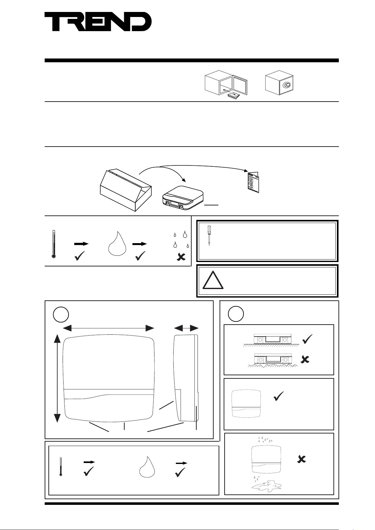
1 INSTALLATION
1.1 UNPACKING
1.2 STORING
-10 °C
(14 °F)
1.3 INSTALLATION - FIXING
+50 °C
(122 °F)
H2O
0
90 %RH
1.3 Installation - Fixing ........................................................ 1
1.4 Installation - Configuration............................................ 6
2 End User Licence Agreement .................................... 14
3 Disposal ...................................................................... 15
3xtend/EINC L/24 Installation
Instructions TG200811
3xtend/EINC L/24 Template TG200813
It is recommended that the installation should
comply with the HSE Memorandum of Guidance
on Electricity at Work Regulations 1989.
For USA install equipment in accordance with
the National Electric Code.
WARNING
Other than removing front covers, do not
!
attempt to open the unit. Failure to comply
may cause damage to the unit.
Dimensions
1
218 mm (8.58")
c
0 °C
(32 °F)
227 mm (8.94")
Bottom cable access
+45 °C
(113 °F)
H2O
60 mm (2.36")
Terminal
access
Rear cable access
0 %RH
Requirements
2
a
b
The unit is UL rated as
'UL916, open energy
management equipment'
d
80 %RH
3xtend/EINC L/24 Installation Instructions TG200811 Issue 3 3/9/08
1
Page 2
3xtend/EINC L/24 Installation Instructions
12345678910
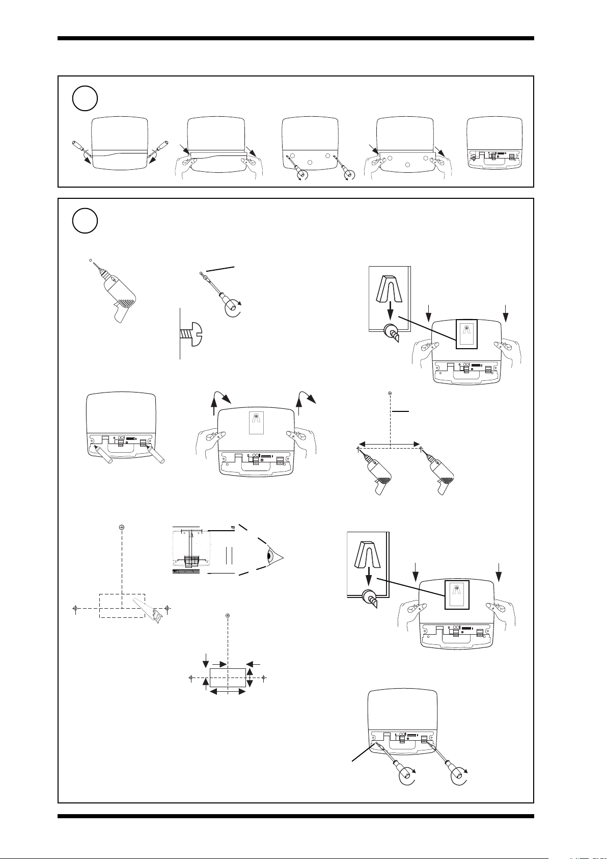
1.3 INSTALLATION - FIXING (Continued)
Remove Covers
3
abcde
12345678910
Mount Unit
4
Either via 3 screw fixing (e.g. for fixing on wall)
ab c
M4, 5, or 6 (pan or CSK)
or No 10 or 12 (CSK)
Rear
view
de
f
Length depends on screw
head projection and screw
type
12345678910
12345678910
170 mm (6.69”)
g Cut rear cable entry hole if required
LERN/24 Installation Instructions - Template
Trend Control Systems Ltd reserves the right to revise this publication from time to time and make changes to the content hereof without
obligation to notify any person of such revisions or changes.
var.com
trendinfo@no
E-mail
Installation Instructions - Template
LERN/24
XXXXXXXXXXXXXXXX
126 mm (4.96”)
88
Novar Hou
A
nternatio
Fax (I
se 24 Queen
B
196 mm (3.78”)
20 mm
(0.78”)
rear cable entry cutout
75 mm (2.95”
37.5 mm (1.48”)
1403 2109
nal) +44 (0)
s Road Weybridge Surrey KT13 9UX Registered in England No 1664519
A 3 hole fixing
A
Screw size 4 off M4 x 16
Hole/drill 5mm
or alternatively
B 3 hole fixing
(Do not use template for 3 hole fixing, see LERN../SM installation instructions, TGxxxxxx sheet 1 step x.)
NOTE: Print to size.
ions below
Check dimens
4"
80 mm (3.15”)
8 mm (0.31”)
)
Website www.trend-controls.com
82
Fax (U
10 cm
40 mm (1.57”)
B
40 mm (1.57”)
A
8
)1403 241 60
K) +44 (0
LERN/24 Installation Instructions TGxxxxxx Issue 1/A dd/mm/yy
1
A
B
170 mm (6.69”)
P.O. Box 34, Horsham, West Sussex, RH12 2YF United Kingdom
0)1403 211 8
one +44 (
Teleph
red office.
Registe
3xtend/EINC L/24 Template TG200813
h
Rear
view
12345678910
40 mm
20 mm
(1.57”)
(0.78”)
80 mm
40 mm
(1.57”)
i
(3.15”)
12345678910
2 x M4, 5, or 6
(No 10 or 12)
2
3xtend/EINC L/24 Installation Instructions TG20081 1 Issue 3 3/9/08
Page 3
Installation Instructions 3xtend/EINC L/24
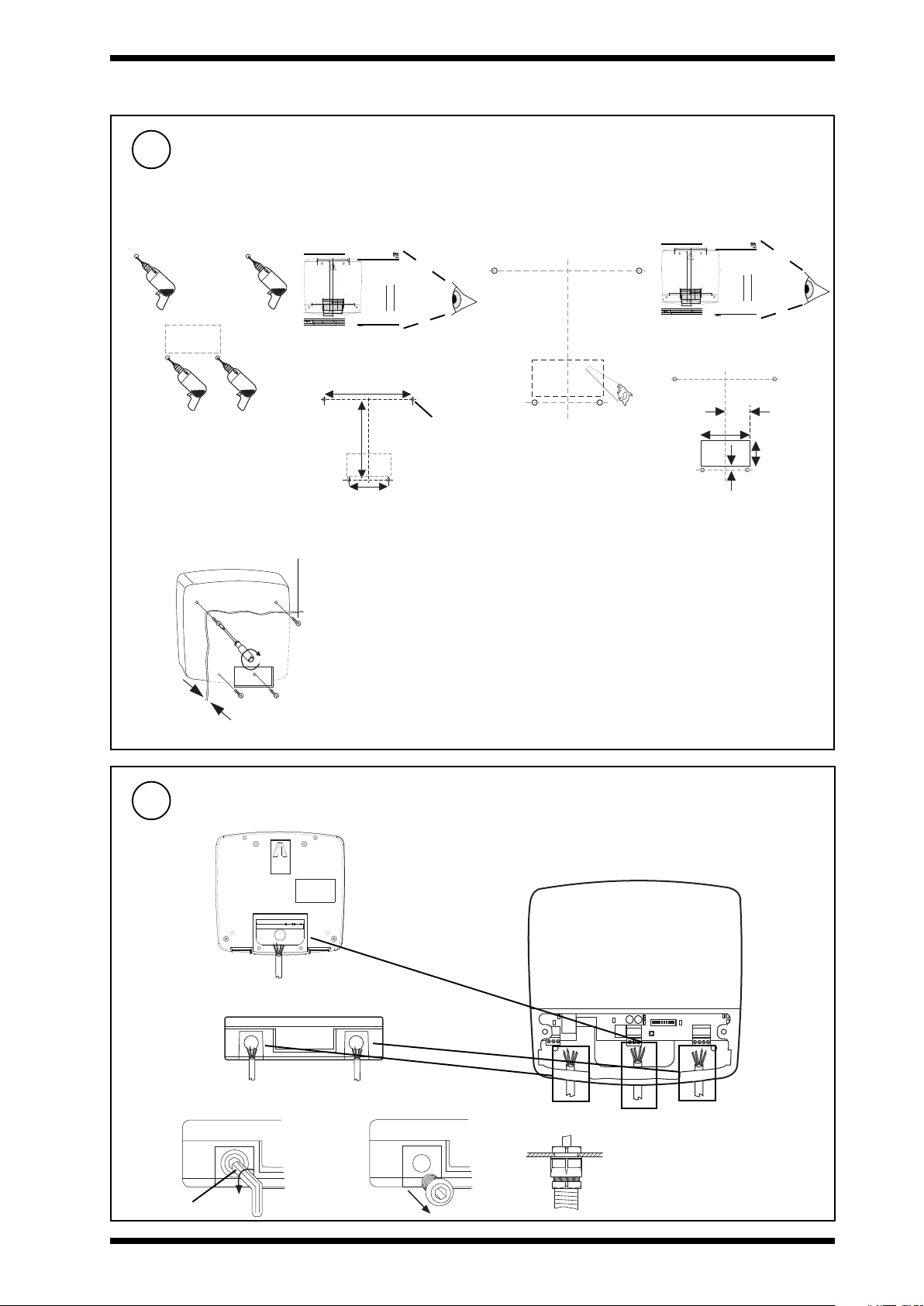
1.3 INSTALLATION - FIXING (Continued)
Mount Unit (Continued)
4
Or via 4 screw fixing (e.g. fixing on a panel)
Cut rear cable entry hole
a
LERN/24 Installation Instructions - Template
Trend Control Systems Ltd reserves the right to revise this publication from time to time and make changes to the content hereof without
o
bli
gation
to
notify any person of such revisions or changes.
E-mail trendinfo@novar.com
Installation Instructions - Template
LERN/24
XXXXXXXXXXXXXXXX
126 mm (4.96”)
A 3 hole fixing
B
A
A
Screw size 4 off M4 x 16
Hole/drill 5mm
or alternatively
B 3 hole fixing
(Do not use template for 3 hole fixing, see LERN../SM installation instructions, TGxxxxxx sheet 1 step x.)
NO
TE: P
rin
t to size.
Check dimensions below
4"
10 cm
40
mm (1
.57”
)
B
40 mm (1.57”)
A
.trend-controls.com
LERN/24 Installation Instructions TGxxxxxx Issue 1/A dd/mm/yy
1
B
170 mm (6.69”)
A
P.O
. B
ox 34
, Horsham, West Sussex, RH12 2YF United Kingdom
Fax (International) +44 (0)1403 210982
Telephone +44 (0)1403 211 888
Registered office. Novar House 24 Queens Road Weybridge Surrey KT13 9UX Registered in England No 1664519
196 mm (3.78”)
80 mm (3.15”)
20 mm
(0.78”)
rear cable entry cutout
8 mm (0.31”)
75 mm (2.95”)
37.5 mm (1.48”)
Web
sit
e www
Fax (UK) +44 (0)1403 241 608
3xtend/EINC L/24 Template TG200813
126 mm (4.96”)
4 holes Ø 5 mm
(3.78”)
196 mm
75 mm
(2.95”)
b
if required
LERN/24 Installation Instructions - Template
Trend Control Systems Ltd reserves the right to revise this publication from time to time and make changes to the content hereof without
obl
iga
tion
to
notify any person of such revisions or changes.
E-mail trendinfo@novar.com
A
B
170 mm (6.69”)
A
37.5 mm (1.48”)
P.O.
Bo
x 34,
Horsham, West Sussex, RH12 2YF United Kingdom
Fax (International) +44 (0)1403 210982
Telephone +44 (0)1403 211 888
Registered office. Novar House 24 Queens Road Weybridge Surrey KT13 9UX Registered in England No 1664519
Installation Instructions - Template
LERN/24
XXXXXXXXXXXXXXXX
126 mm (4.96”)
A 3 hole fixing
B
A
Screw size 4 off M4 x 16
Hole/drill 5mm
or alternatively
B 3 hole fixing
(Do not use template for 3 hole fixing, see LERN../SM installation instructions, TGxxxxxx sheet 1 step x.)
NOTE: Print to size.
196 mm (3.78”)
80 mm (3.15”)
40
mm
20 mm
(0.78”)
rear cable entry cutout
8 mm (0.31”)
75 mm (2.95”)
Webs
ite
www.t
Fax (UK) +44 (0)1403 241 608
Check dimensions below
4"
10
cm
(1.5
7”)
B
40 mm (1.57”)
A
rend-controls.com
LERN/24 Installation Instructions TGxxxxxx Issue 1/A dd/mm/yy
1
3xtend/EINC L/24 Template TG200813
40 mm (1.57”)
80 mm (3.15”)
40 mm
(1.57”)
8 mm
(0.31”)
c
10 mm
5
4 x M4 x 16 mm
Max
Route Cables
Rear entry
Bottom entry
Fit M20 (¾”) cable
glands
ab
c
8 mm Allen key
3xtend/EINC L/24 Installation Instructions TG200811 Issue 3 Issue 3 3/9/08
12345678910
3
Page 4
3xtend/EINC L/24 Installation Instructions
0
I
1.3 INSTALLATION - FIXING (Continued)
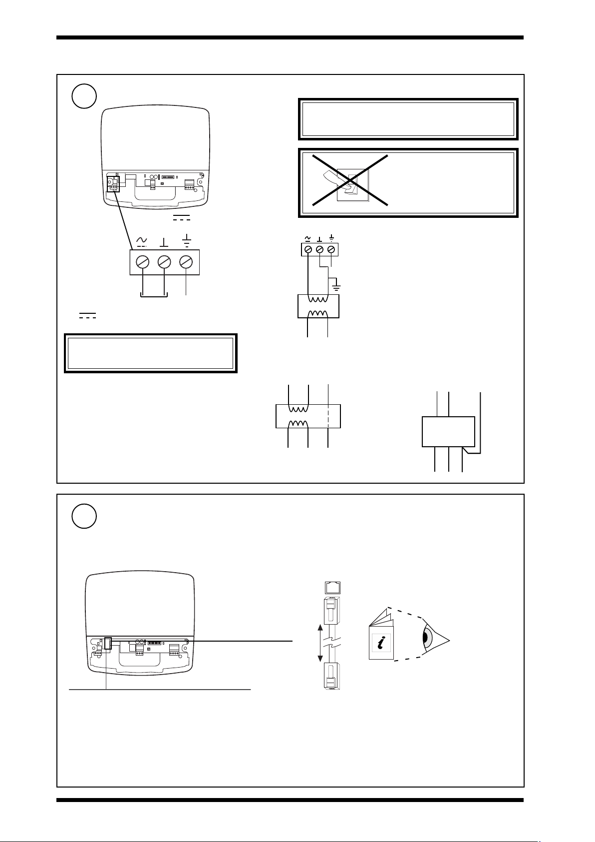
Connect Power
28 to 36 Vdc or 24 Vac ±10 %, 50/60 Hz, Consumption <= 8VA
6
12345678910
28 - 36 V
24 V ~
Terminal size 0.14 to
2.5 mm2 (25 to 14
AWG). For UL rated
units use 22 to 14
AWG cable.
24 Vac
~
28 Vdc
CAUTION: Do not apply mains power to
this connector.
24 Vac
+28V 0V
E
E
WARNING: This apparatus must be earthed (via
supply earth/ground terminal).
DO NOT
SWITCH ON
Using a 230V/24 Vac transformer
Some transformers (as in typical plant room
installions) are earthed on one side of the
secondary; therefore care must be taken to
E
ensure that the earthed side of the transformer
24Vac
LN
Using the ACC/24VAC transformer Using the PSR/230/24-2.5 power supply
secondary is connected to the middle terminal
of the power connector. If the polarity of the
connection is incorrect the unit will not power
up. If this happens you should swap the left
most and center connections over and the
unit should power up unless there is another
fault.
Connect Ethernet
7
Connect to an Ethernet hub
Use Ethernet cable.
12345678910
Maximum Cable distance
100 m (109 yds)
Ethernet
24Vac
E
ACC/24VAC
LNE
230 Vac
3xtend/EINC L
100 m (109 yds)
Ethernet hub/switch
E0V+28V
PSR/230/24-2.5
LNE
RJ45 Connector
IQ System
Products
Engineering
Guide TE200369
RJ45 Connector
4
3xtend/EINC L/24 Installation Instructions TG20081 1 Issue 3 3/9/08
Page 5
Installation Instructions 3xtend/EINC L/24
T R
T R
T R
T R
X
T
T
R
R
1 2 3 4
T- T+ R- R+
X
T
T
R
R
T
T
R
R
+
LON
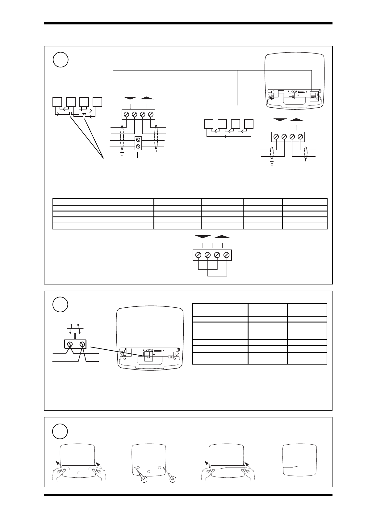
1.3 INSTALLATION - FIXING (Continued)
Connect Current Loop
8
4 wire
T- T+ R- R+
1 2 3 4
Additional terminals
Maximum Cable distance
Belden 9182 1000 m (1090 yds) 700 m (765 yds) 500 m (545 yds) 2
Belden 9207 1000 m (1090 yds) 500 m (545 yds) 350 m (380 yds) 2
IQ System TP/1/1/22/HF/200 (Belden 8761)
IQSystem TP/2/2/22/HF/200 (Belden 8723)
IMPORTANT
If the 3xtend/EINC L’s current loop is not to be connected (i.e
3xtend/EINC L is only to interface between Ethernet and
LONWORKS network) a loop back should be fitted as shown
Cable 9k6 baud 19k2 baud 38k4 baud * No. of Wires
Terminal size 0.14 to 2.5
mm2 (25 to 14 AWG). For UL
rated units use 22 to 14
AWG cable.
700 m (765 yds) 350 m (380 yds) 250 m (270 yds) 2
500 m (545 yds) 250 m (270 yds) 125 m (135 yds) 4
T R
Terminal size 0.14 to 2.5
mm2 (25 to 14 AWG). For UL
rated units use 22 to 14
AWG cable.
Note only 1 INC type node on a single Lan.
T- T+ R- R
1 2 3 4
T R
2 wire
T R T R
12345678910
Connect LONWORKS® Bus
9
1 2
12345678910
Polarity independent
Terminal size 0.14 to 2.5 mm2 (25 to 14 AWG).
For UL rated units use 22 to 14 AWG cable.
Normal current loop Lan cable is not recommended.
Do not use screened cable.
Maximum Cable distance
Recommended
Cables
Belden 85102 500 m (545 yds) 500 m (545 yds)
Trend
TP/1/0/16/HF/200
(Belden 8471)
UL Level IV, 22 AWG 500 m (545 yds) 400 m (430 yds)
JY(St) Y2 x 2 x 0.8 500 m (545 yds) 320 m (350 yds)
TIA568A Cat. 5, 24
AWG
If used with LPT-10 (powered bus), cable lengths differ - see
‘Link Power Transceiver User’s Guide (078-0105-01C)’.
Available from Echelon.
Note that the 3xtend/EINC L is not compatible with LONC.
The LONC must be bound on a LONWORKS network, and the
3xtend/EINC L cannot be bound.
Max bus length
500 m (545 yds) 400 m (430 yds)
450 m (490 yds) 250 m (270 yds)
Max node to
node
Replace Covers
10
ab c d
3xtend/EINC L/24 Installation Instructions TG200811 Issue 3 Issue 3 3/9/08
5
Page 6

3xtend/EINC L/24 Installation Instructions
12345678910
O
I
ADDRESS
O
1.4 INSTALLATION - CONFIGURATION
1
Fix Unit
1
Note that this product may involve
LONWORKS system integration. This
procedure should only be performed by
!
an installer with LONWORKS expertise.
Section 1.3
Switch off
2
Remove Covers
3
abcde
12345678910
Set Internetwork Address (Lan number)
4
address
1, 4 to 9, 11 to 119
0, 2, 3, 10 or >119
ON
N
e.g.
Address = 2 + 16 + 64 = 82
If address < 100, INC Mode If address = > 100, Internetwork Extension Mode
Internetwork
(on Ethernet)
Note that only one internetwork device is allowed on a Lan therefore ensure that the 3xtend/EINC L’s LAN number is not
used by another INC type device.
Note that it is recommended that the LONWORKS network is not used where a high level of communication traffic is expected,
e.g. joining internetworks or where there are many IQ System devices on many IQ System Lans being accessed across
an internetwork routed through the LONWORKS network. An alternative topology should be used, such as an Ethernet
internetwork.
6
3xtend/
EINC L
Lan
(on current loop)
Internetwork
(on LONWORKS)
NOT SET
SET
Address = A
Lan
= A
/
Internetwork
(on Ethernet)
3xtend/EINC L/24 Installation Instructions TG20081 1 Issue 3 3/9/08
= A
3xtend/EINC L
Lan
Lan
= A
/
Lan
= A
/
3xtend/
EINC L
Internetwork
(on current loop)
Internetwork
(on LONWORKS)
Page 7

Installation Instructions 3xtend/EINC L/24
O F F F R E E
1.4 INSTALLATION - CONFIGURATION (Continued)
Set Current Loop Baud Rate
5
5
12345678910
NOT SET
Baud Rate = C
SET
=C
38k4 baud
3xtend/EINC L
=C
19k2 baud
9k6 baud
SET LONWORKS Terminator Link
6
*
T e r m in a t o r
12345678910
Lon - FTT (free topology)
*
T e r m in a t o r
=C
=C
Note 1: 38k4 Lan not available with IQ2xx, IQ1xx, INC, LINC,
CNC, CNC2, INC2,and TMN.
Note 2: 38k4 Internetwork not available with INC, and LINC.
O F F F R E E
OFF
No terminator, LONWORKS
bus must be terminated
FREE
Use to terminate LONWORKS
bus at 3xtend/EINC L
elsewhere.
*
T e r m i n a t o r
Star topology Bus topologyLoop topology
Do not allow wires to
cross on a loop
*Terminate LONWORKS bus at one end only
Terminated using IQLRouter’s LONWORKS terminator link
IQL
IQL
IQL
y
z
x
xyzw
IQL
xyzw
xyzw
3xtend/
EINC L
SCN
Recommend terminate at 3xtend/EINC L using LONWORKS terminator link
Otherwise terminate elsewhere using LONTERMINATOR. Terminate
LONWORKS bus at one end only.
Terminator
100 mF, 50 V min
LonA
LonB
IQLROUTER
A
4
3
1
2
IQLROUTER
A
4
3
1
2
B
4
3
1
w
2
Maximum 64 nodes per LONWORKS
network segment.
Maximum 40 IQLs (and LONCs)
per virtual Lan
B
4
3
1
2
Terminated using IQLRouter’s LONWORKS terminator link
100 mF, 50 V min
3xtend/EINC L/24 Installation Instructions TG200811 Issue 3 Issue 3 3/9/08
7
Page 8

3xtend/EINC L/24 Installation Instructions
1.4 INSTALLATION - CONFIGURATION (Continued)
Install DHCP Server
7
If the IP address settings (IP address, subnet mask,
default router, and WINs server) are to be supplied by
a DHCP server install one on the same network segment.
8
Read Licence
9
Read and agree to End User
3
Licence Agreement (these
instructions Section 2).
10
The 3xtend/EINC L will attempt to obtain its
IP settings from a DHCP server if one does
not exist it will go into link/local mode.
Check Status LEDs
11
Ethernet OK LED
Power LED
Ethernet Link LED
Normal Operation Indication (shown after 2 minutes)
+ ++
Power LED Ethernet OK LED Lon OK LED Current Loop OK LED
If LEDs are not as above after 2 minutes check table below.
12345678910
Install WINS Server
If host names are to be used for IP addressing
across a router install a WINS server on the system
if one is not already installed.
Switch On
0
I
Lon OK LED
TX LED
RX LED
Current Loop OK LED
Ethernet Data LED
Note that if connecting using a
24Vac transformer and the unit
does not power up check the
polarity of the power connections
(see page 1-4 step (6)).
DELylsuounitnoCgnihsalFylsuounitnoCffO
)eulB(rewoPyhtlaeHtinUyldetaepereciwtgnihsalF
KOtenrehtE
)neerG(
KOnoL
)neerG(
)neerG(
)wolleY(
pooLtnerruC
)neerG(KO
)wolleY(XR=rekcilfthgils,KOtiucricrevieceR
)wolleY(XT.lamron-rekcilfthgilS
kniLtenrehtE
ataDtenrehtE
wtenretninoL:rofsdnoces42yrevetuobagnihsalF
.lamron
.detrohseb
tluafelbaC.deviecergniebataD ebyamelbaC(
KOtliubkro
dnuofecivedtenrehtE.)ytluafelbaC(tluaF ebyamelbaC(
snoitacinummoc
03>
KOtliubkrowtenretnitenrehtE tenrehtEoN-DELrew
rO
rO
NOWSKRO
L-s021<
NOWSKRO
L-s021>
rO
NOWSKRO
LrehtooN
rO
NOWSKRO
L
KOtliubnaL/krowtenretninoL:rofsdnoces21yrev
rO
FtiucricrevieceR
ricrettimsnarT-gnirekcilFoN
yamtiuc
etuobagnihsalF
etnihsalflliW
lbaliavatonsisserddaPI
.)erehweslestluafrofkcehC(
laerasDELneerg3llafI
oPhtiwyletanretlagnihsalF
:rofs21yrevetuobagnihsalF
iubkrowtenretnitenrehtE-s09<
.)erehweslestluafrofkcehC(
.)erehweslestluafrofkcehC(
.dnuofsecived
rehweslestluafrofkcehC(ylreporp
.deviecergniebatad-tsafsrekcil
.sgnittestenrehtEgniniatbO-s003<
sgnittestenrehtEniatbootelbanU-s0
.gnidl
rebmuntropPDUemastasecivedrehtooN
.
.tluafadepolevedsahrotcennoC/elbaC
.gnidliubkrowtenretni
yltcerrocdetanimrettonkrowten
.)e
.)sDELXRdnaXTkcehC(detcennoctoN
.dettimsnartgniebsiatad-tsafsrekcilF
tenrehtEoneblliwereht,e
.sDELrehtokcehctluafasahtinuyldetaepergnihsalF
.sserddadilavni-gnihsalfos
.).rotcennocro/dnaelbackcehC(.dnuofnoitcennoc
ylreporpgnidliubtonkrowtenretnitenrehtE-s09>
ylreporpgnidliubtonkrowtenretni
.gnidliubnaL/krowtenretnipooLtnerruC-s06<
gnidliubtonkrowtenretni/naLpooLtnerruC-s06>
.gnitacinummocsitinuehtnehwyltnettimr
.detcennocsidtiucricrettimsnarT-s21yrevetuobasehsalF
tluaFrewoP
ytluaFtinU
ytluaFtinU
ytluaFtinU
ytluaFtinU
nekorb/detcennocsid
ytluaFtinU
ytluaFtinU
detrohsseriwrevieceR
.dnuofecivedtenrehtEoN
)ytluafrodetcennocsid
.dnuofecivedtenrehtEoN
)ytluafrodetcennocsid
8
3xtend/EINC L/24 Installation Instructions TG20081 1 Issue 3 3/9/08
Page 9

Installation Instructions 3xtend/EINC L/24
1.4 INSTALLATION - CONFIGURATION (Continued)
Connect to 3xtend/EINC L with IP Tool
12
Either over Ethernet or Local PC Ethernet Connection
XCITE/XA crossover adaptor
order separately (XCITE/XA/5 pack
of 5)
Router
3xtend/
EINC L
Initially access EINC L via its MAC address (written on label)
Router
SET v6
(including IP Tool)
Local PC (Ethernet) connection can be either to adjacent Ethernet
hub using standard cable only, or directly to EINC L using
standard cable and crossover adaptor, XCITE/XA.
SET Manual TE200147
IP Tool Manual TE200638
Configure Addressing Details with IP Tool
13
3xtend/EINC L Data Sheet TA200800
IP Tool Manual TE200638
The 3xtend/EINC L’s addressing information can be set up automatically (automatic addressing) or manually (manual
addressing). When set up automatically the addressing details are obtained from a DHCP server, if a DHCP server is not being
used or fails the 3xtend/EINC L enters link/local mode where it autonegotiates its IP address with other devices on its Ethernet
segment. Alternatively the settings can be specified manually. When automatic addressing is used the 3xtend/EINC L’s IP
address may vary, with manual addressing the IP address is fixed. The addressing details can be viewed or configured using
IPTool. The table below describes the options that must be set up for each addressing mode.
Addressing Method
Automatic Manual
DHCP Link/Local
DHCP Server Required Ye s Must not be i nsta lle d No
WINS Server Required Yes No if all devices on same
DHCP Set to Yes. This is the default. Set to Yes. This is the default. Set to No using IPTool
IP Address Set by DHCP server Autonegotiated with other
Subnet Mask Set by DHCP server Uses 255.255.0.0 Must be specified using IPTool
Default Router Set by DHCP server N/A Must be specified using IPTool
WINS Server Set by DHCP server N/A Must be specified using IPTool
HostName De fa ult value us ed . Ca n be
specified using IPTool.
UDP Port De fa ult value us ed . Ca n be
specified using IPTool.
Identifier D efa ult value us ed . Ca n be
specified using IPTool.
Internetwork Across Routers S e t up hos t nam e a nd sub ne t
mask of remote devi ces using
IPTool.
Virtual CNCs Required Set C NC ad dress and port
number of required vCNCs with
IPTool. For vCNCs in alarm
mode also set up the host name
of devi ce to which alarms are to
be sent.
subnet, otherwise requi red.
devices on same subnet.
Default value used. Can be
specified using IPTool.
Default value used. Can be
specified using IPTool.
Default value used. Can be
specified using IPTool.
Not available Set up host name/IP address,
Set C NC address and port
number of required vCNCs with
IPTo ol. For vC NCs in alarm
mode als o set up the h ost name
of device to which alarms are to
be sent.
Only required if connection to
de vi ce s i s to b e ma d e usi ng
host na mes.
Must be specified using IPTool.
It is possible to use a fixed IP
address on a DHCP system
providing the DHCP server is
set not to allocate the address.
Default value used. Can be
specified using IPTool.
Default value used. Can be
specified using IPTool.
Default value used. Can be
specified using IPTool.
and subnet mask of remote
devices using IPTool.
Set CNC address and port
number of required vCNCs with
IPTool. For vCNCs in alarm
mode al so set u p t h e I P add ress
of host name of device to which
alarms are to be sent
3xtend/EINC L/24 Installation Instructions TG200811 Issue 3 Issue 3 3/9/08
9
Page 10

3xtend/EINC L/24 Installation Instructions
1.4 INSTALLATION - CONFIGURATION (Continued)
Configure Addressing Details with IP Tool (Continued)
13
3xtend/EINC L Data Sheet TA200800
IP Tool Manual TE200638
The table below describes the addressing parameters that need to be set up.
retemaraPnoitpircseD egnahcotnehW
sserddA
eludoM
--renrehtE
pi
eludoM
reifitnedI otstluafedtI.naLehtyfitnediotdesulebalretcarahc
retuoRtluafeD ehtfitneserasegassem
PCHD .desusignisserddalaunamrocitamotuarehtehwseificepS
emantsoH emankrowtenehthtiwderetsigersitahtgnirtsretcar
*sserddAPI ehtnoecivedhcaerofsserddaPIeht,sserddaPIehT)etirw/daer(
revreSSNIW.revreSSNIWehtfosserddaPIehtseificepS)etirw/daer(
*ksaMtenbuS tonsecivedllarofemasehtebtsumtiksamtenbusehT)etirw/daer(
troPPDU otdesutrop)locotorPmargataDresU(P
-04A
ehtni.sserddaCAM
=egnaRsretcarahc*?;{(\/ton
pseb
.0.0.0.0otstluafedti
.0.0=egnaR
ortluafed
toehthtiwdetaitogenotua
alaunamfI
=egnaR
ahc-51A)ylno/daer(
x_DNERTotstluafedtI
ehtnisrebmunfo.sserddaCAM
=egnaRsretcarahc*?;{(\/ton-sretcarahcciremunahpla51
.0.0.0.0otstluafedti
.0.0.0.0otstluafedti
yehttahtserusne
ehtfI.revres
.0.552.552.552otstluafedti
DUehT)etirw/daer(
.21675ot
53556ot0=egnaR
srebmunfospuorg3tsalehterazzdna,yy,xxerehW.zz_yy_xx_DNERT
-sretcarahcciremunahpla04
hcihwotretuorehtfosserddaPIehT
E/dnetx3ehtsatenbusemasehtnoretuorafosserdda
.retuorafoedisrehtoehttenbustenrehtE
552.552.552.552ot0.0
0.0.552.552ottessiksamtenbus
trehtaremanybgnitcennocrofrevresserddaPInah
aoteuqinuebtsumkrowtentenrehtE
.tenbusemasehtnoseivedrehtohtiw
amebtsumtidetcelessignisserddalaunamfI
552.552.552.552ot0.0.0.0=egnaR
ficepssignisserddacitamotuanehW
mtidetcelessignisserddalaunamfI
552.552.552.552ot0.0.0.0=egnaR
.tenbusemasehtnoera
52.552.552.552ot0.0.0.0=egnaR
5
owtenretninaetaercotdesusecivedllA
eniatbositideificepssignisserddacitamotuanehW
.seY=tluafeD,desuPCHD=seY,oNroseY
.sehsalcsserddadiov
tignitarepotonsitirorevresPCHDonerehtfI.revres
.testonsitirorevresPCHDonerehtfI.revres
.0.0.0.0ottessitirevresPCHDoner
PIehtottesebdluohstI.tenbuslacolehtnotonsisserddanoitanitsed
tsumtI.LCNI
,sretuorsnapstahtkrowtenretninadliubotsiLCNIEehtfideifice
naotdetcennocCPaybdesuebotsisCNClautrivehtfoenofiro
PCHDamorfd
.testonsitignitarepotonsitirorevresPCHDonerehtfI.revres
sacsihtni,denifedyllaunamebtsumtidetcelessignisserddalaunamfI
e
,ksam
tenbus,sserddaPIehtdeificepssignisserddacitamotuanehW
PCHDamorfdeniatboerasretemaraprevresSNIWdna,retu
sisserddaPIehtgnitarepotonsitirorevresPCHDonerehtfI.revres
PIehtdna,tenbusemasehtnosecivedreh
,ksamtenbus,sserddaPIs'LCNIEehtdetcelessignisserdd
.denifedyllaunamebtsumsretemaraprevresSNIWdna,retuortluafed
spuorg3tsalehterazzdna,yy,xxerehW.zz_yy_x
PCHDamorfdeniatbositideificepssignisserddacitamotuanehW
detaitogenotuasi
esacsihtni,denifedyllaun
hW
PCHDamorfdeniatbositidei
esacsihtni,denifedyllaunamebtsu
sihT.krowtenretninarosnaLdliuboteratahtsretuorybdetarapes
PCHDamorfdeniatbositideificepssignisserddacitamotuanehW
esacsihtni,denifedyllaunamebtsumtidetcelessignisserddalaunamfI
.krowtentenrehtEehtrevosecivedmetsysQIrehtohtiwetacinummoc
stluafeD.tropemasesutsumkr
.desugnieb
.degnahceb
revres
aunamnehW
.desugnieb
.deriuqer
.desugnieb
pg.e
.elbatiustonsitluafednehW
signisserddalaunamnehW
otsiedomgnisserddanehW
ebnacgnisserddalaunaM
ahtiwmetsysanodesu
ehtgedivorprevresPCHD
edi
stuosisserddas'LCNIE
ehtybdengissaegnareht
stonsitluafednehW
.elbatiu
signisserddal
signisserddalaunamne
otnoitcennocdna,desugnieb
sisemantsohgnisusecived
signisserddalaunamnehW
elbatiustonsitluafednehW
rodesugniebydaerlatro
)setis(skrowtenretnielpitlum
.tenbusemasehtnoderiuqer
*Note that when setting up the Ethernet addressing ensure that there is only one subnet on a network segment.
10
3xtend/EINC L/24 Installation Instructions TG20081 1 Issue 3 3/9/08
Page 11

Installation Instructions 3xtend/EINC L/24
1.4 INSTALLATION - CONFIGURATION (Continued)
Configure Addressing Details with IP Tool (Continued)
13
Para me te r Des c r ip tio n When to cha nge
Remote
EINC
Modules
Virtual
CNC
Modules
I P Address (read/write) T he IP address/host n ame of th e r emote dev ice on Eth ern et.
Subnet mask (read/write) The subnet mask for the remote device.Range = 0.0.0.0 to
At least two devices from each each subnet should be specifed. For increased reliabili ty details of additio nal devi ces
sho uld be specified . If automatic ad dr e ss ing is bein g used th e de vices must be specified u sing hostnames, and if manual
addressing is being used the li st should contai n the devices with the lowest IP addresses. The table must be placed in
all devices on the network.
Alarm IP
Address
CNC Address The device address of the virtual CNC on EINC L’s Lan. It is set to
Port Address The TCP port used by the virtual CNC. It is set unused by default and
The host name or IP address of the remote device on Ethernet.
Range = 0.0.0.0 to 255.255.255.255. Default=0.0.0.0
255.255.255.255 Default=0.0.0.0
The host name or IP address of the alarm target supervisor that is
connected to the Ethernet network if operating in alarm mode. Setting
this u p switch es the v irtu al CNC into alar m mode, an d preven ts th e virt ual
CNC being used as a CNC by a supervisor . 0 w ill sw itch t h e virtu al CNC
back into supervi s or mode. Default=Unus ed
unused by default, and the virtual CNC will not operate until its address
is set up. It can be set to any valid address (1 to 119 excluding
addresses 2, 3, and 10). 0 will disable the vi rtual CNC.
then defaults to 10000 plus the cnc address when the cnc address is
set up, but can subsequently be changed.Range = 1 to 32767.
If internetwo rk is to be bui lt
across routers.
If the virtual CNC is to be u sed
to send alarms to a supervisor
over Ethernet.
I f the virt u al CNC is t o be u s ed.
I f the virt u al CNC is t o be u s ed.
Configure Optional Settings Using SET
14
Parameter Description
Address
Module
Remote
Devices
Enter configuration mode using SET. The top level
a
prompt will be displayed as below.
Lan Alarm
Address
Lan Alarm
Lan
Alarm
Language
Internetwork
Alarm
Address
Internetwork
Alarm Lan
Disable
vCNC A live
Alarms
Send
Remote
Broadcasts
The alarm target device address for alarms generated by the current loop network when it is operating
as a Lan. It can be set to any valid address (1 to 119 excluding addresses 2, 3, and 10). 0 stops the
alarms being transmitted.
The target Lan number for alarms generated by the current loop network when it is operating as a Lan.
It can be set to any valid address (1 to 1 19 excluding addr esses 2, 3, and 10). 0 stops the alarms being
transmitted.
The langu age used for the networ k al ar m s. 0 =English, 1= S pa nish, 2= Fin nish, 3=Sw edish, 4= N or w egian,
5=Danish, 6=German, 7=Italian, 8=Portuguese, 9=French.
The alarm target device address for internetwork alarms. It can be set to any valid address (1 to 119
excluding addresses 2, 3, and 10). 0 stops the alarms being transmitted.
Th e al ar m t arget Lan n u m ber f or in ter n etw ork al arms . It can be set to an y v al id address (1 t o 1 19 ex c luding
addresses 2, 3, and 10). 0 stops the alarms being transmitted.
Enabl es/ disabl es device on- l in e, an d dev ice dead al ar ms generated by virtual CNCs. R an ge= Yes or N o,
Yes = alarms disabled. Default = No.
Specif ies w hether r em ot e br oadc ast m ess ages or dir ect ed m ess ages a re used to buil d t he int er network
across routers.
If set to use broadcast messages (Yes) the messages used to build the internetwork across routers
will be sent to the default router requesting a broadcast message to all devices on the remote
device’s subnet as well as the remote device specified in the module.
If set not to use broadcast messages (No) the messages used to build the i nternetwork across routers
will only be sent (by di rect messaging) to the device specified in the module.
Thi s option should only be turned off if the routers have remote broadcast messaging disabled.
I f broadcasting is turned off , details of as m any dev ice’s as poss ibl e f r om ea ch su bnet should be entered
in the remote devices table to enable the internetwork to be built in the event of a failure.
SET Manual TE200147
3xtend/EINC L Data Sheet TA200800
b
Note that it may be necessary to set up a virtual CNC in the
3xtend/EINC L if one is not available elsewhere on the network.
Configure the optional settings the relevant upper
case letter and pressing ENTER. If a value has been
changed X+ENTER will confirm it and return to the
top menu, whereas Q+ENTER will quit and return
with the value unchanged. The table below describes
the settings.
3xtend/EINC L/24 Installation Instructions TG200811 Issue 3 Issue 3 3/9/08
11
Page 12

3xtend/EINC L/24 Installation Instructions
XTEND -400007096
3 X t r e a m
L A N
M A C A d d r
00.10.70.00.UD.BB
O / S
S/No:
I P A d d r
Location
M A C A d d r
00.10.70.00.UD.BB
S/No:
Q3B____X73010003
I P A d d r
3
3
SET, or 963
963
1.4 INSTALLATION - CONFIGURATION (Continued)
Configure Optional Settings Using SET (Continued)
14
retemaraPnoitpircseD
pi-tenrehtE
eludom
klatnoL
eludom
etadpU
etomeR
seciveD
gnikrowteN
delbasiD
klatnoL
delbanE
ruoyypoC
CNIEetomer
rehtoottsil
)N/Y(sCNIE
resU
NIP aybtnesebtsumro,yalpsidamorfnogolot
seludoM
Note that if required the parameters configured using IP Tool can also be configured in the same way.
lliwecivedehtrehtehwseificepS
Ls'ecivedehtselbasid/selbanE
NO
W
SKRO
.snoitacinummoc
iwstenbuslladnatenbuslacolottsilscniEetomerehtseipoC
.krowtentenrehtEehtnoseciveddnerTrehtorofhcraes
tsilniCNIEdnasLCNIE/dnetx3ht
resuehtybderetneebtsumtahtrebmuntigid-4ehT
.egnahcaesirohtuaotrosivrepus/loot
Tear off Label Strip
M A C A d d r
00.10.70.00.UD.BB
IP A d d r
S/No:
Location
Q3B____X73010003
15
Write on Label
M A C A d d r
00.10.70.00.UD.BB
I P A d d r
3 X t r e a m
XTND -400007096
M A C A d d r
00.10.70.00.UD.BB
I P A d d r
S/No:
Q3B____X7301000
Location
S/No:
Q3B____X7301000
L A N
O / S
e.g. location/identifier
recommended
S/No:
M A C A d d r
00.10.70.00.UD.BB
Q3B____X73010003
Location
IP A d d r
S/No:
3X tre a m
XTND -400007096
Q3B____X73010003
LA N
O /S
M A C A d d r
00.10.70.00.UD.BB
IP A d d r
16
IP Address, Location, Lan, address
Replace Covers
17
ab c d
Check Virtual CNCs
Virtual CNCs in Alarm Mode
18
Virtual CNCs in Supervisor Mode
using temporary
connection
12
CNC in
Supervisor mode
EINC L
using permanent
connection
E t h e r n e t
CNCA
CNCB
CNCFCNCE
CNCDCNCC
CNCHCNCG
EINC L
3xtend/EINC L/24 Installation Instructions TG20081 1 Issue 3 3/9/08
E t h e r n e t
CNCA
CNCFCNCE
CNC in
Alarm mode
CNCB
Alarm from system sent to VCNC
CNCDCNCC
CNCHCNCG
Page 13

Installation Instructions 3xtend/EINC L/24
EINC
456
2
789
3
101112
4
131415
5
161718
6
192021
7
222324
8
252627
9
282930
10
+ 0
+ 0
+ 0
+ 0
+ 0
+ 0
+ 0
+ 0
+ 0
123
1
+ 0
343536
12
373839
13
404142
14
A
313233
P
11
434445
15
464748
16
100-240V
OKRX
P0
P0
P0
P0
P0
P0
EINC
45 6
2
78 9
3
101112
4
131415
5
161718
6
192021
7
222324
8
252627
9
282930
10
+ 0
+ 0
+ 0
+ 0
+ 0
+ 0
+ 0
+ 0
+ 0
12 3
1
+ 0
343536
12
373839
13
404142
14
A
313233
P
11
434445
15
464748
16
100-240V
OKRX
P0
P0
P0
P0
P0
P0
EINC
456
2
789
3
101112
4
131415
5
161718
6
192021
7
222324
8
252627
9
282930
10
+ 0
+ 0
+ 0
+ 0
+ 0
+ 0
+ 0
+ 0
+ 0
123
1
+ 0
343536
12
373839
13
404142
14
A
313233
P
11
434445
15
464748
16
100-240V
OKRX
P0
P0
P0
P0
P0
P0
EINC
456
2
789
3
101112
4
131415
5
161718
6
192021
7
222324
8
252627
9
282930
10
+ 0
+ 0
+ 0
+ 0
+ 0
+ 0
+ 0
+ 0
+ 0
123
1
+ 0
343536
12
373839
13
404142
14
A
313233
P
11
434445
15
464748
16
100-240V
OKRX
P0
P0
P0
P0
P0
P0
EINC
45 6
2
78 9
3
101112
4
131415
5
161718
6
192021
7
222324
8
252627
9
282930
10
+ 0
+ 0
+ 0
+ 0
+ 0
+ 0
+ 0
+ 0
+ 0
12 3
1
343536
12
373839
13
404142
14
A
313233
P
11
434445
15
464748
16
100-240V
OKRX
P0
P0
P0
P0
P0
P0
EINC
45 6
2
78 9
3
101112
4
131415
5
161718
6
192021
7
222324
8
252627
9
282930
10
+ 0
+ 0
+ 0
+ 0
+ 0
+ 0
+ 0
+ 0
+ 0
12 3
1
+ 0
343536
12
373839
13
404142
14
A
313233
P
11
434445
15
464748
16
100-240V
OKRX
P0
P0
P0
P0
P0
P0
1.4 INSTALLATION - CONFIGURATION (Continued)
Check Communications
19
If address <100
Lan
(on current loop)
EINC
Internetwork
(on Ethernet)
161718
456
131415
192021
123
252627
222324
101112
282930
789
+0
+0
+0
+0
+0
+0
+0
+0
+0
+0
100-240V
OKRX
343536
313233
373839
434445
464748
404142
24V
24V
0V
OK
Tx
Rx
24VAC24VAC24V
24V
230V
12345
6
7
AC
91011
8
345
If address =>100
Lan
(on current loop)
Internetwork
(on Ethernet)
EINC
161718
456
131415
192021
123
252627
222324
101112
282930
789
+0
+0
+0
+0
+0
+0
+0
+0
+0
+0
100-240V
OKRX
343536
313233
373839
434445
464748
404142
24V
24V
0V
OK
Tx
Rx
24VAC24VAC24V
24V
230V
12345
7
6
AC
91011
8
345
EINC L
Lan
(on current loop)
EINC L
Internetwork
(on current loop)
INC
Lan
(on current loop)
IQL
Internetwork
(on L W
ON ORKS
network)
IQL
Internetwork
(on L W
ON ORKS
network)
Internetwork
(on Ethernet)
Internetwork
(on Ethernet)
(on current loop)
456
131415
123
101112
789
+0
+0
+0
+0
+0
100-240V
OKRX
(on current loop)
161718
456
131415
123
101112
789
+0
+0
+0
+0
+0
100-240V
OKRX
24V
0V
Lan
EINC
EINC L
161718
192021
252627
222324
282930
+0
+0
+0
+0
+0
343536
313233
373839
434445
464748
404142
24V
24V
0V
Tx
24VAC24VAC24V
24V
230V
12345
6
7
AC
91011
8
345
OK
Rx
Lan
(on current loop)
Internetwork
(on L W
ON ORKS
network)
IQL
Internetwork
(on Ethernet)
Lan
EINC
EINC L
192021
252627
222324
282930
+0
+0
+0
+0
343536
313233
373839
434445
464748
404142
24V
Internetwork
(on current loop)
IQL
Internetwork
ON ORKS
(on L W
network)
Internetwork
(on Ethernet)
INC
OK
Tx
Rx
24VAC24VAC24V
24V
230V
12345
7
6
91011
8
AC
345
Lan
(on current loop)
(on current loop)
161718
456
131415
123
101112
789
+0
+0
+0
+0
+0
+0
100-240V
OKRX
(on current loop)
161718
456
131415
192021
123
101112
789
+0
+0
+0
+0
+0
+0
+0
100-240V
V
V
V
OKRX
313233
24
24
0
12345
Lan
EINC
EINC L
192021
252627
222324
282930
+0
+0
+0
+0
343536
313233
373839
434445
464748
404142
24V
24V
0V
OK
Tx
24VAC24VAC24V
24V
230V
12345
7
6
AC
91011
8
345
Rx
Lan
(on current loop)
IQL
Internetwork
(on L W
ON ORKS
network)
Lan
EINC
IQL
EINC L
252627
222324
282930
+0
+0
+0
343536
373839
434445
464748
404142
Internetwork
(on current loop)
Internetwork
(on L W
ON ORKS
network)
INC
OK
Tx
Rx
24VAC24VAC24V
24V
230V
7
6
AC
91011
8
345
Lan
(on current loop)
3xtend/EINC L/24 Installation Instructions TG200811 Issue 3 Issue 3 3/9/08
13
Page 14

3xtend/EINC L/24 Installation Instructions
2 END USER LICENCE AGREEMENT
EULA Terms
• You have acquired a 3xtend/EINC L (“Device”) that includes software licensed by Trend Control Systems Ltd from one or more
software licensors (“Trend Control Systems Ltd Software Suppliers”). Such software products, as well as associated media
printed materials and “online” or electronic documentation (“SOFTWARE”) are protected by international intellectual property
laws and treaties. The SOFTWARE is licensed, not sold. All rights reserved.”
• IF YOU DO NOT AGREE TO THIS END USER LICENSE AGREEMENT (“EULA”), DO NOT USE THE DEVICE OR COPY THE
SOFTWARE. INSTEAD, PROMPTLY CONTACT TREND CONTROL SYSTEMS LTD FOR INSTRUCTIONS ON RETURN OF THE
UNUSED DEVICE(S) FOR A REFUND. ANY USE OF THE SOFTWARE INCLUDING BUT NOT LIMITED TO USE ON THE DEVICE
WILL CONSTITUTE YOUR AGREEMENT TO THE EULA (OR RATIFICATION OF ANY PREVIOUS CONSENT).
• GRANT OF SOFTWARE LICENSE. This EULA grants you the following license:
• You may use the SOFTWARE only on the DEVICE
• NOT FAULT TOLERANT. THE SOFTWARE IS NOT FAULT TOLERANT. TREND CONTROL SYSTEMS LTD HAS
INDEPENDENTLY DETERMINED HOW TO USE THE SOFTWARE IN THE DEVICE, AND TREND CONTROL SYSTEMS LTD’S
SOFTWARE SUPPLIERS HAS RELIED UPON TREND CONTROL SYSTEMS LTD TO CONDUCT SUFFICIENT TESTING TO
DETERMINE THAT THE SOFTWARE IS SUITABLE FOR SUCH USE.
• NO WARRANTIES FOR THE SOFTWARE. THE SOFTWARE is provided “AS IS” and with all faults. THE ENTIRE RISK
AS TO SATISFACTORY QUALITY, PERFORMANCE, ACCURACY, AND EFFORT (INCLUDING LACK OF NEGLIGENCE)
IS WITH YOU. ALSO, THERE IS NO WARRANTY AGAINST INTERFERENCE WITH YOUR ENJOYMENT OF THE SOFTWARE
OR AGAINST INFRINGEMENT. IF YOU HAVE RECEIVED ANY WARRANTIES REGARDING THE DEVICE OR THE SOFTWARE,
THOSE WARRANTIES DO NOT ORIGINATE FROM, AND ARE NOT BINDING ON, TREND CONTROL SYSTEMS LTD’S
SOFTWARE SUPPLIERS.
• Note on Java Support. The SOFTWARE may contain support for programs written in Java. Java technology is not fault
tolerant and is not designed, manufactured, or intended for use or resale as online control equipment in hazardous
environments requiring fail-safe performance, such as in the operation of nuclear facilities, aircraft navigation or
communication systems, air traffic control, direct life support machines, or weapons systems, in which the failure of Java
technology could lead directly to death, personal injury, or severe physical or environmental damage. Sun Microsystems,
Inc. has contractually obligated Trend Control Systems Ltd’s software suppliers to make this disclaimer.
• No Liability for Certain Damages. EXCEPT AS PROHIBITED BY LAW, TREND CONTROL SYSTEMS LTD’S SOFTWARE
SUPPLIERS SHALL HAVE NO LIABILITY FOR ANY INDIRECT, SPECIAL, CONSEQUENTIAL OR INCIDENTAL DAMAGES
ARISING FROM OR IN CONNECTION WITH THE USE OR PERFORMANCE OF THE SOFTWARE. THIS LIMITATION SHALL
APPLY EVEN IF ANY REMEDY FAILS OF ITS ESSENTIAL PURPOSE. IN NO EVENT SHALL TREND CONTROL SYSTEMS
LTD’S SOFTWARE SUPPLIERS BE LIABLE FOR ANY AMOUNT IN EXCESS OF U.S. TWO HUNDRED FIFTY DOLLARS
(U.S.$250.00).
• Limitations on Reverse Engineering, Decompilation, and Disassembly. You may not reverse engineer, decompile,
or disassemble the SOFTWARE, except and only to the extent that such activity is expressly permitted by applicable law
notwithstanding this limitation.
• SOFTWARE TRANSFER ALLOWED BUT WITH RESTRICTIONS. You may permanently transfer rights under this EULA
only as part of a permanent sale or transfer of the Device, and only if the recipient agrees to this EULA. If the SOFTWARE
is an upgrade, any transfer must also include all prior versions of the SOFTWARE.
14
3xtend/EINC L/24 Installation Instructions TG20081 1 Issue 3 3/9/08
Page 15

Installation Instructions 3xtend/EINC L/24
3 DISPOSAL
WEEE Directive :
At the end of their useful life the packaging and
product should be disposed of via a suitable
Do not dispose of with normal household waste. Do not burn.
recycling centre.
3xtend/EINC L/24 Installation Instructions TG200811 Issue 3 Issue 3 3/9/08
15
Page 16

3xtend/EINC L/24 Installation Instructions
Please send any comments about this or any other Trend technical publication to techpubs@trendcontrols.com
© 2008 Honeywell Technologies Sàrl, ECC Division. All rights reserved. Manufactured for and on behalf of the Environmental and Combustion Controls
Division of Honeywell Technologies Sàrl, Ecublens, Route du Bois 3, Switzerland by its Authorized Representative, Trend Control Systems Limited.
Trend Control Systems Limited reserves the right to revise this publication from time to time and make changes to the content hereof without
obligation to notify any person of such revisions or changes.
Trend Control Systems Limited
P.O. Box 34, Horsham, West Sussex, RH12 2YF, UK. Tel:+44 (0)1403 211888 Fax:+44 (0)1403 241608 www. trend-controls.com
Trend Controls Systems USA
6670 185th Avenue NE, Redmond, Washington 98052, USA. Tel: (425)897-3900, Fax: (425)869-8445 www. trend-controls.com
16
3xtend/EINC L/24 Installation Instructions TG200811 Issue 3 3/9/08
 Loading...