

Page 1
Important: Retain these instructions
Installation Instructions
3xtend/EINC L/230
Node Controller
CONTENTS
1 Installation .................................................................... 1
1.1 Unpacking ..................................................................... 1
1.2 Storing........................................................................... 1
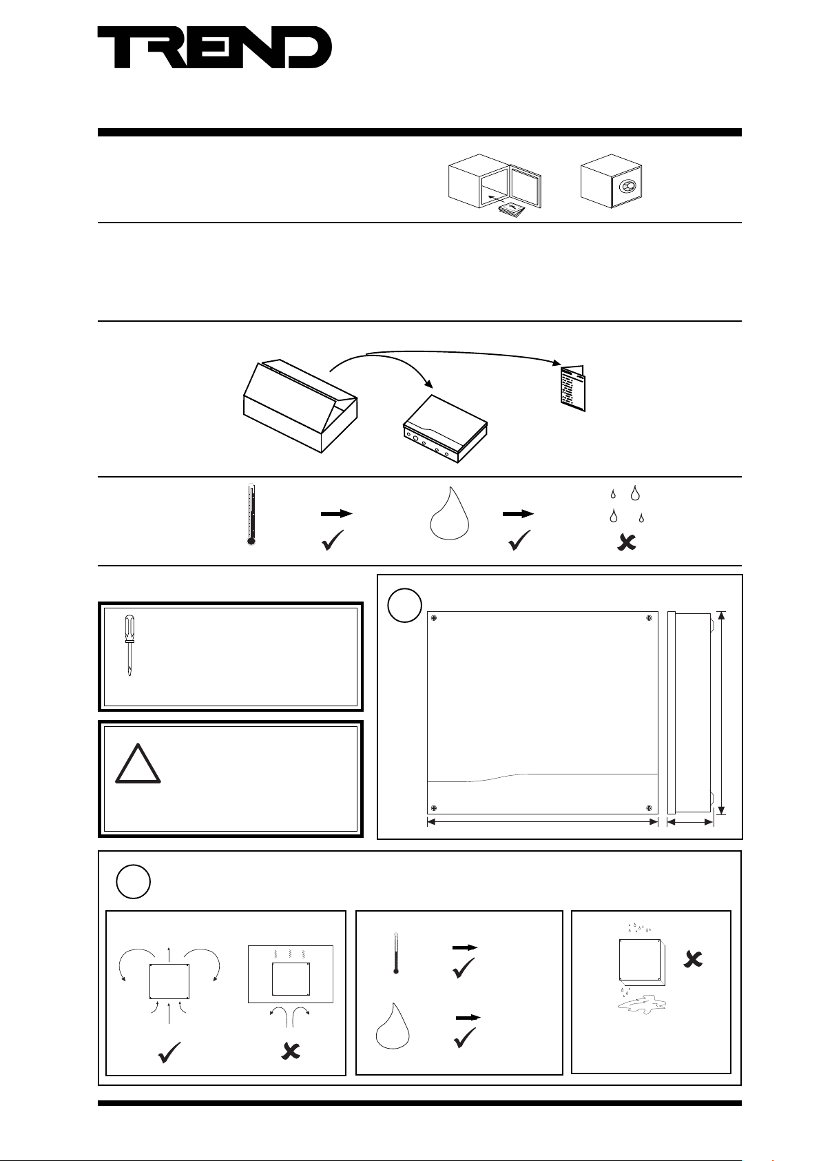
1 INSTALLATION
1.1 UNPACKING
1.2 STORING
-10 °C
(14 °F)
1.3 INSTALLATION - FIXING
It is recommended that the installation
should comply with the HSE Memorandum
of Guidance on Electricity at Work
Regulations 1989.
For USA install equipment in accordance
with the National Electric Code.
+50 °C
(122 °F)
1
1.3 Installation - Fixing........................................................ 1
1.4 Installation - Configuration............................................ 5
2 Replacing a Fuse........................................................ 13
3 End User Licence Agreement .................................... 15
4 Disposal ...................................................................... 16
3xtend/EINC L/230 Installation
Instructions TG200812
0
90 %RH
H2O
Dimensions
WARNING
Other than removing front covers,
do not attempt to open the unit.
!
Failure to comply may cause
damage to the unit.
Requirements
2
a
3xtend/EINC L/230 Installation Instructions TG200812 Issue 3 3/9/08
b
0 °C
(32 °F)
0 %RH
H2O
266 mm (10.47”)
302 mm (11.89”) 60 mm (2.36”)
c
+45 °C
(113 °F)
80 %RH
1
Page 2
3xtend/EINC L/230 Installation Instructions
12345678910
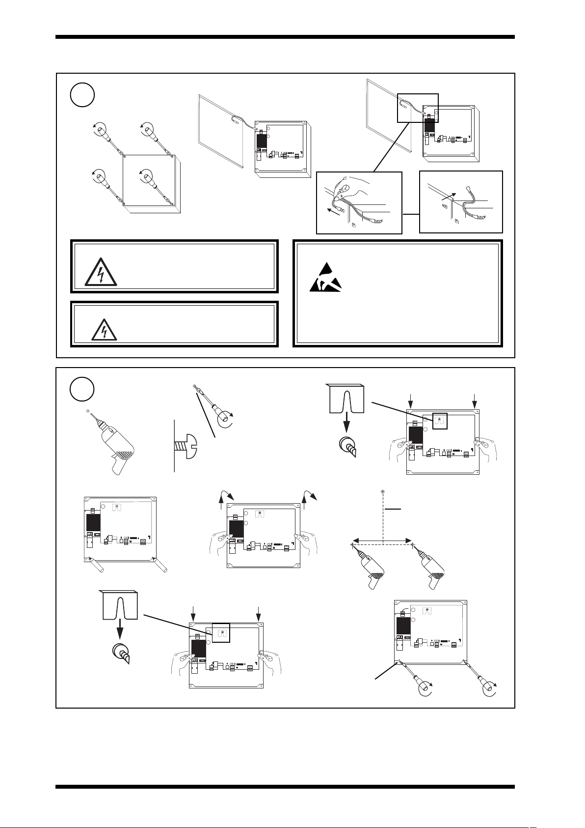
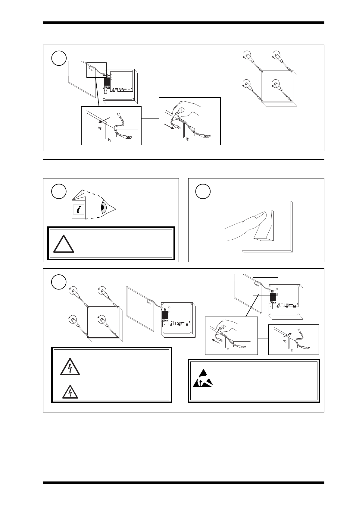
1.3 INSTALLATION - FIXING (Continued)
Remove Cover
3
a
WARNING: Opening the panel may expose
dangerous voltages.
417-IEC-5036
WARNING: The connecting leads may be
connected to supplies. Isolate
before touching.
b
c
12345678910
Caution: This unit contains static sensitive
devices. Suitable anti-static
precautions should be taken
throughout this operation to prevent
damage to the units.
BS EN100015/1 Basic Specification: protection of
electrostatic sensitive devices.
4
a
d
h
Mounting
12 34 567 89 10
b
M4, 5, or 6 (pan or CSK)
or No 10 or 12 (CSK)
e f
12 34 567 89 10
Rear view
12 34 567 89 10
Rear view
c
12 34 567 89 10
Length depends on screw
head projection and screw
type
255 mm (10”)
i
12 34 567 89 10
2 x M4, 5, or 6
(No 10 or 12)
2
3xtend/EINC L/230 Installation Instructions TG200812 Issue 3 3/9/08
Page 3
Installation Instructions 3xtend/EINC L/230
~
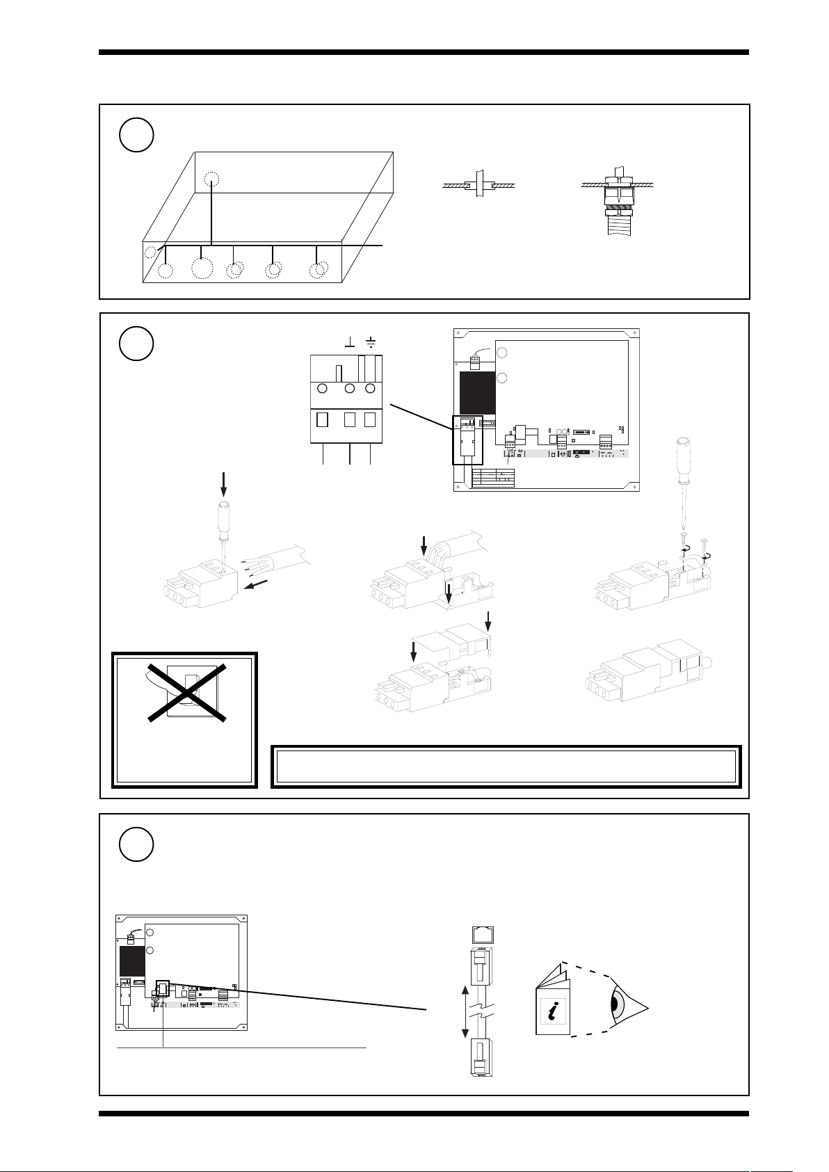
1.3 INSTALLATION - FIXING (Continued)
Route Cables
5
Pushouts
Either or
use M20 grommet
use M20 Copex glands
Connect Power
6
Use shrouded plug
0.5 to 2.5 mm2 (20 to 14
AWG)
a
0
I
L N E
L N E
b
d
1 23 4 5 67 8 9 10
O K
28 -3 6 V
24 V
S/ No :
M AC A d dr
00 .1 0. 70 .0 0. UD .B B
Q 3B __ _ _X 73 0 10 00 3
Lo ca tio n
IP A dd r
S/ No :
3X tr ea m
X TN D -4 00 0 07 09 6
Q 3B __ _ _X 73 0 10 00 3
LA N
O /S
M AC A d dr
00 .1 0. 70 .0 0. UD .B B
IP A d dr
R S2 3 2
ET H ER NE T
LI NK DA T A
T RE N D L AN
L ON
LO N
RxTx
O K
T- T+ R - R +
AD D RE SS - BA UD
LO N
SR V PI N
TE R M
1 2
O K
1 2 3 4
c
e
DO NOT APPLY
POWER
WARNING: This apparatus must be earthed (via mains supply cable).
Connect Ethernet
7
Connect to an Ethernet hub
Use Ethernet cable.
12 34 5 67 89 10
OK
28 -36 V
ET HE RNE T
24 V
LIN K DA TA
Maximum Cable distance
100 m (109 yds)
3xtend/EINC L/230 Installation Instructions TG200812 Issue 3 3/9/08
TR EN D LA N
LO N
LO N
RS 23 2
1 2
RxT x
OK
T- T + R- R +
AD DR ESS - B AU D
LO N
OK
1 2 3 4
SR V P IN
TE RM
E t h e r n e t
3xtend/EINC L
RJ45 Connector
100 m (109 yds)
RJ45 Connector
Ethernet hub/switch
IQ System
Products
Engineering
Guide TE200369
3
Page 4
3xtend/EINC L/230 Installation Instructions
T R
T R
T R
T R
X
T
T
R
R
4 5 6 7
T- T+ R- R+
X
T
T
R
R
T
T
R
R
+
LON
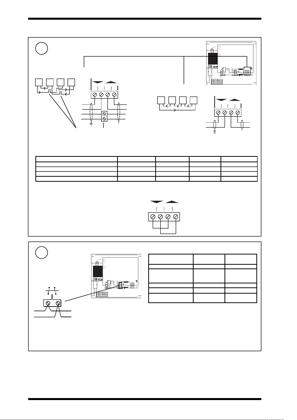
1.3 INSTALLATION - FIXING (Continued)
Connect Current Loop
8
4 wire
T- T+ R- R+
4 5 6 7
Terminal size 0.14 to 2.5
mm2 (25 to 14 AWG).
T R
T R
2 wire
T R T R
OK
28 -36 V
ET HE RN ET
24 V
LIN K DA TA
S/ No:
M AC Ad dr
00 .10 .70 .00 .U D.B B
Q3 B_ __ _X 730 10 00 3
Lo cat ion
IP Ad dr
S/ No:
3X tre am
XT ND -4 00 00 709 6
Q3 B_ __ _X 730 10 00 3
LA N
O/ S
M AC Ad dr
00 .10 .70 .00 .U D.B B
IP A ddr
Terminal size 0.14 to 2.5
mm2 (25 to 14 AWG).
Additional terminals
Note only 1 INC type node on a single Lan.
Maximum Cable distance
Cable 9k6 baud 19k2 baud 38k4 baud * No. of Wires
Belden 9182 1000 m (1090 yds) 700 m (765 yds) 500 m (545 yds) 2
Belden 9207 1000 m (1090 yds) 500 m (545 yds) 350 m (380 yds) 2
IQ System TP/1/1/22/HF/200 (Belden 8761)
IQSystem TP/2/2/22/HF/200 (Belden 8723)
700 m (765 yds) 350 m (380 yds) 250 m (270 yds) 2
500 m (545 yds) 250 m (270 yds) 125 m (135 yds) 4
IMPORTANT
If the 3xtend/EINC L’s current loop is not to be connected (i.e
3xtend/EINC L is only to interface between Ethernet and
T- T+ R- R
1 2 3 4
LONWORKS network) a loop back should be fitted. as shown
12 3 45 67 89 10
TR E ND LA N
LO N
LO N
RS 23 2
1 2
RxT x
OK
T- T + R - R+
AD DR ESS - B AU D
LO N
OK
1 2 3 4
SR V P IN
TE RM
Connect LONWORKS® Bus
9
OK
28 -36 V
ET HE RN ET
24 V
LIN K DA TA
S/ No:
M AC Ad dr
00 .10 .70 .00 .U D.B B
Q3 B_ __ _X 730 10 00 3
Lo cat ion
IP Ad dr
S/ No:
3X tre am
XT ND -4 00 00 709 6
Q3 B_ __ _X 730 10 00 3
LA N
O/ S
M AC Ad dr
00 .10 .70 .00 .U D.B B
1 2
Polarity independent
Terminal size 0.14 to 2.5 mm
(25 to 14 AWG).
Normal current loop Lan cable is not recommended.
Do not use screened cable.
4
IP A ddr
2
Maximum Cable distance
Recommended
Cables
Max bus length
Max node to
node
Belden 85102 500 m (545 yds) 500 m (545 yds)
Trend
TP/1/0/16/HF/200
12 3 45 67 89 10
TR E ND LA N
LO N
LO N
RS 23 2
OK
T- T + R - R+
AD DR ESS - B AU D
LO N
1 2 3 4
SR V P IN
TE RM
1 2
(Belden 8471)
UL Level IV, 22 AWG 500 m (545 yds) 400 m (430 yds)
RxT x
OK
JY(S t ) Y2 x 2 x 0.8 500 m (5 45 yds) 320 m (350 yds)
TIA568A Cat. 5, 24
AWG
500 m (545 yds) 400 m (430 yds)
450 m (490 yds) 250 m (270 yds)
Note that the 3xtend/EINC L is not compatible with LONC.
The LONC must be bound on a LONWORKS network, and the
3xtend/EINC L cannot be bound.
3xtend/EINC L/230 Installation Instructions TG200812 Issue 3 3/9/08
Page 5
Installation Instructions 3xtend/EINC L/230
O
I
12345678910
1.3 INSTALLATION - FIXING (Continued)
Replace Cover
10
a
12345678910
1.4 INSTALLATION - CONFIGURATION
Fix Unit
1
1
3xtend/EINC L/24
Installation Instructions
section 1.3
b
Switch off
2
Note that this product may involve
LONWORKS system integration. This
procedure should only be performed by
!
an installer with LONWORKS expertise.
Remove Cover
3
b
a
WARNING: Opening the panel may expose
dangerous voltages.
417-IEC-5036
WARNING: The connecting leads may be
connected to supplies. Isolate before
touching.
c
12345678910
Caution: This unit contains static sensitive devices.
Suitable anti-static precautions should be
taken throughout this operation to prevent
damage to the units.
BS EN100015/1 Basic Specification: protection of electrostatic
sensitive devices.
3xtend/EINC L/230 Installation Instructions TG200812 Issue 3 3/9/08
5
Page 6

3xtend/EINC L/230 Installation Instructions
1 2 3 4
RS 23 2
RxT x
OK
OK
LO N
1 2
28 -36 V
24 V
ET HE RN ET
TR E ND LA N
T- T + R - R+
LIN K DA TA
LO N
OK
LO N
TE RM
AD DR ESS - B AU D
SR V P IN
12 3 45 67 89 10
LA N
M AC Ad dr
00 .10 .70 .00 .U D.B B
O/ S
S/ No:
Q3 B_ __ _X 730 10 00 3
IP Ad dr
Lo cat ion
M AC Ad dr
00 .10 .70 .00 .U D.B B
S/ No:
Q3 B_ __ _X 730 10 00 3
XT ND -4 00 00 709 6
IP Ad dr
3X tre am
ADDRESS
O
1.4 INSTALLATION - CONFIGURATION (Continued)
Set Internetwork Address (Lan number)
4
address
1, 4 to 9, 11 to 119
0, 2, 3, 10 or >119
e.g.
ON
Address = A
N
NOT SET
Lan
= A
/
Lan
= A
3xtend/EINC L
Lan
= A
/
SET
Address = 2 + 16 + 64 = 82
If address < 100, INC Mode If address = > 100, Internetwork Extension Mode
Internetwork
(on Ethernet)
3xtend/
EINC L
Internetwork
(on LONWORKS)
Internetwork
(on Ethernet)
Lan
(on current loop)
Lan
= A
/
3xtend/
EINC L
Internetwork
(on current loop)
Internetwork
(on LONWORKS)
Note that only one internetwork device is allowed on a Lan therefore ensure that the 3xtend/EINC L’s LAN number is not used
by another INC type device.
Note that it is recommended that the LONWORKS network is not used where a high level of communication traffic is expected,
e.g. joining internetworks or where there are many IQ System devices on many IQ System Lans being accessed across
an internetwork routed through the LONWORKS network. An alternative topology should be used, such as an Ethernet
internetwork.
5
38k4 baud
19k2 baud
9k6 baud
6
Set Current Loop Baud Rate
NOT SET
SET
SET LONWORKS Bus Terminator Link
OK
28 -36 V
ET HE RN ET
24 V
LIN K DA TA
S/ No:
M AC Ad dr
00 .10 .70 .00 .U D.B B
Q3 B_ __ _X 730 10 00 3
Lo cat ion
IP Ad dr
S/ No:
3X tre am
XT ND -4 00 00 709 6
Q3 B_ __ _X 730 10 00 3
LA N
O/ S
M AC Ad dr
00 .10 .70 .00 .U D.B B
IP Ad dr
12 3 45 67 89 10
TR E ND LA N
LO N
LO N
RS 23 2
OK
T- T + R - R+
AD DR ESS - B AU D
LO N
1 2 3 4
SR V P IN
TE RM
1 2
OK
28 -36 V
ET HE RN ET
24 V
LIN K DA TA
S/ No:
M AC Ad dr
00 .10 .70 .00 .U D.B B
Q3 B_ __ _X 730 10 00 3
Lo cat ion
IP Ad dr
S/ No:
3X tre am
XT ND -4 00 00 709 6
Q3 B_ __ _X 730 10 00 3
LA N
O/ S
M AC Ad dr
00 .10 .70 .00 .U D.B B
IP A ddr
Baud Rate = C
3xtend/EINC L
=C
=C
=C
=C
Note 1: 38k4 Lan not available with IQ2xx, IQ1xx, INC, LINC,
CNC, CNC2, INC2,and TMN.
Note 2: 38k4 Internetwork not available with INC, and LINC.
O F F F R E E
OFF
No terminator, LONWORKS
bus must be terminated
RxT x
OK
elsewhere.
O F F F R E E
FREE
Use to terminate LONWORKS
bus at 3xtend/EINC L
12 3 45 67 89 10
TR E ND LA N
LO N
LO N
RS 23 2
1 2
RxT x
OK
T- T + R - R+
AD DR ESS - B AU D
LO N
OK
1 2 3 4
SR V P IN
TE RM
6
3xtend/EINC L/230 Installation Instructions TG200812 Issue 3 3/9/08
Page 7

Installation Instructions 3xtend/EINC L/230
1.4 INSTALLATION - CONFIGURATION (Continued)
SET LONWORKS Bus Terminator Link (Continued)
6
*
T e r m i n a t o r
Loop topology
*Terminate LONWORKS bus at one end only
Recommend terminate at 3xtend/EINC L using LONWORKS terminator link
Otherwise terminate elsewhere using LONTERMINATOR. Terminate
LONWORKS network at one end only.
Terminator
Lon - FTT (free topology)
*
T e r m i n a t o r
Star topology
100 mF, 50 V min
*
T e r m i n a t o r
Bus topology
Do not allow wires to
cross on a loop
Terminated using IQLRouter’s LONWORKS terminator link
SCN
3xtend/
EINC L
LonA
LonB
IQLROUTER
A
4
1
3
2
IQL
B
4
3
1
w
2
IQL
y
z
x
xyzw
Maximum 64 nodes per LONWORKS
segment
Maximum 40 IQLs (and LONCs)
per virtual Lan
IQLROUTER
A
4
3
1
2
IQL
B
4
3
1
2
IQL
xyzw
xyzw
100 mF, 50 V min
Install DHCP Server
If the IP address settings (IP address, subnet
7
mask, default router, and WINs server) are to be
supplied by a DHCP server install one on the
system if one is not already installed.
9
3
Read and agree to End User
Licence Agreement (these
instructions Section 2).
Check Status LEDs
11
Ethernet OK LED
Power LED
M AC Ad dr
IP Ad dr
Ethernet Link LED
Normal Operation Indication (shown after 2 minutes)
3X tre am
M AC Ad dr
IP A ddr
Terminated using IQLRouter’s LONWORKS terminator link
Install WINS Server
If host names are to be used to connect to the
8
3xtend/EINC L install a WINS server on the system
if one is not already installed.
Switch OnRead Licence
10
The 3xtend/EINC L will attempt
to obtain its IP address settings
from a DHCP server if one does not exist
it will go into link/local mode.
Lon OK LED
TX LED
OK
28 -36 V
ET HE RN ET
24 V
LIN K DA TA
S/ No:
00 .10 .70 .00 .U D.B B
Q3 B_ __ _X 730 10 00 3
Lo cat ion
S/ No:
XT ND -4 00 00 709 6
Q3 B_ __ _X 730 10 00 3
LA N
O/ S
00 .10 .70 .00 .U D.B B
12 3 45 67 89 10
TR E ND LA N
LO N
LO N
RS 23 2
1 2
RxT x
OK
T- T + R - R+
AD DR ESS - B AU D
LO N
OK
1 2 3 4
SR V P IN
TE RM
RX LED
Current Loop OK LED
Ethernet Data LED
0
I
Power LED Ethernet OK LED Lon OK LED Current Loop OK LED
+ ++
If LEDs are not as above after 2 minutes check table below.
LED Continuously Flashing Off Continuously
Power (Blue) Unit Healthy Flashing twice repeatedly
IP address is not available, t here will be no Ethernet
communications
< 300 s - Obtaining Ethernet settings.
> 300 s - Unable to obtain Ethernet settings
(Check for faults elsewhere).
Flashing repeatedly unit has a fault check other
LEDs.
If all 3 green LEDs are also flashing-invalid address.
3xtend/EINC L/230 Installation Instructions TG200812 Issue 3 3/9/08
Power Fault
Unit Faulty
7
Page 8

3xtend/EINC L/230 Installation Instructions
1.4 INSTALLATION - CONFIGURATION (Continued)
Check Status LEDs (Continued)
11
DELylsuounitnoCgnihsalFylsuounitnoCffO
)neerG(
KOnoL
)neerG(
)neerG(
)wolleY(
KOtenrehtE
pooLtnerruC
)neerG(KO
)wolleY(XRthgils,KOtiucricrevieceR
)wolleY(XT.lamron-rekcilfthgilS
kniLtenrehtE
ataDtenrehtE
KOtliubkrowtenretnitenrehtE tenrehtEoN-DELrewoPhti
wyletanretlagnihsalF
:rofs21yrevetuobagnihsalF
owtenretnitenrehtE-s09<
.gnidliubkr
.)erehweslestluafrofkcehC(
rO
ntropPDUemastasecivedrehtooN
.rebmu
rO
.tluafadepolevedsahrotcennoC/elbaC
etninoL:rofsdnoces42yrevetuobagnihsalF
KOtliubkrowtenr
NO
W
L-s021<
SKRO
NO
W
L-s021>
SKRO
.)erehweslestluafrofkcehC(ylreporp
rO
NO
W
LrehtooN
SKRO
.dnuofsecived
rO
NO
W
L
KOtliubnaL/krowtenretninoL:rofsdnoces21yrev
SKRO
etuobagnihsalF
yltcerrocdetanimrettonkrowten
rehweslestluafrofkcehC(ylreporp
.)e
rO
.)sDELXRdnaXTkcehC(detcennoctoN
ihsalflliW
.deviecergniebatad-tsafsrekcilFtiu
.lamron=rekcilf
T-gnirekcilFoN
rettimsnar
.detrohsebyamtiucric
.detcennocsid
ebsiatad-tsafsrekcilF
.dettimsnartgni
dnuofecivedtenrehtE.)ytluafelbaC(tluaFecivedtenrehtEo
tluafelbaC.deviecergniebataDecivedtenrehtEoN
.).rotcennocro/dnaelbackcehC(.dnuofnoitcennoc
ylreporpgnidliubtonkrowtenretnitenrehtE-s09>
.gnidliubkrowtenretni
gnidliubtonkrowtenretni
.gnidliubnaL/krowtenretnipooLtnerruC-s06<
gnidliubtonkrowtenretni/naLpooLtnerruC-s06>
.gnitacinummocsitinunehwyltnettimretn
tiucricrettimsnarT-s21yrevetuobasehsalF
N
ytluaFtinU
ytluaFtinU
ytluaFtinU
cricrevieceR
nekorb/detcennocsid
ytluaFtinU
detrohsseriwrevieceR
ytluaFtinU
ebyamelbaC(.dnuof
)ytluafrodetcennocsid
ebyamelbaC(.dnuof
)ytluafrodetcennocsid
Connect to 3xtend/EINC L with IP Tool
12
Either over Ethernet
Router
3xtend/EINC L
Initially access 3xtend/EINC L via its MAC address (written on
label)
8
SET v6
(including IP Tool
or Local PC Ethernet Connection
XCITE/XA crossover adaptor
order separately (XCITE/XA/5
pack of 5)
SET v6
(including IP Tool)
12 345 67 891 0
OK
28 -36 V
ETH ERN ET
24 V
LIN K DA TA
TR EN D LA N
LO N
LO N
RS 232
RxTx
OK
T- T+ R - R +
AD DRES S - B AUD
LO N
OK
1 2 3 4
SR V PIN
TER M
1 2
Local PC (Ethernet) connection can be either to adjacent
Ethernet hub using standard cable only, or directly to EINC
using standard cable and crossover adaptor, XCITE/XA.
SET Manual TE200147
IP Tool Manual TE200638
3xtend/EINC L/230 Installation Instructions TG200812 Issue 3 3/9/08
Page 9

Installation Instructions 3xtend/EINC L/230
1.4 INSTALLATION - CONFIGURATION (Continued)
Configure Addressing Details with IP Tool
13
The 3xtend/EINC L’s addressing information can be set up automatically (automatic addressing) or manually (manual addressing).
When set up automatically the addressing details are obtained from a DHCP server, if a DHCP server is not being used or fails
the 3xtend/EINC L enters link/local mode where it autonegotiates its IP address with other devices on its Ethernet segment.
Alternatively the settings can be specified manually. When automatic addressing is used the 3xtend/EINC L’s IP address may
vary, with manual addressing the IP address is fixed. The addressing details can be viewed or configured using IPTool. The
table below describes the options that must be set up for each addressing mode.
Addressing Method
Automatic Manual
DHCP Link/Local
DHCP Server Required Yes Must not be installed No
WINS Server Required Yes No i f all devices on same
DHCP Set to Yes. This is the d e fa ult. Set to Yes. This is the default. Set to No usi ng IPTool
IP Addre ss Set by DHCP server Autonegotiated with other
Subnet Mask Set by DHCP server Uses 255.255.0.0 Must be specified using IPTool
Defa u lt Router Set by DHCP server N/A Must be specified using IPTool
WINS Server Set by DHCP server N/A Must be specified using IPTool
HostName Default value used. Can be
specified using IPTool.
UDP Port Default value used. Can be
specified using IPTool.
Identifier Default value used. Can be
specified using IPTool.
Internetwork Across Routers Se t up ho st na me and sub net
mask of remote de vices using
IPTool.
Virtual CNCs Required Set CNC ad dress and port
number of required vCNCs with
IP Tool. For vCNCs in alarm
mode also set up the host name
of device to which alarms are to
be sent.
subnet, otherwise required.
devices on same subnet.
Default value used. Can be
specified using IPTool.
Default value used. Can be
specified using IPTool.
Default value used. Can be
specified using IPTool.
Not available Set up host name/IP ad dress,
Set CNC address and port
number of required vCNCs with
IP Tool. For vCNCs in alarm
mode also set up the host name
of device to which alar ms are to
be sent.
3xtend/EINC L Data Sheet TA200800
IP Tool Manual TE200638
Only required if connection to
de vi ce s is t o be ma d e usi ng
hos t names .
Must be specified using IPTool.
It is possible to use a fixed IP
address on a DHCP system
providing the DHCP server is
set not to a llo c a te the a d dress.
Default value used. Can be
specified using IPTool.
Default value used. Can be
specified using IPTool.
Default value used. Can be
specified using IPTool.
and subnet mask of remote
devices using IP Tool.
Set CNC address and port
number of required vCNCs with
IPTool. For vC NCs in alarm
mode al so set u p th e IP addr ess
of host name of device to which
alarms are to be sent
The table below describes the addressing parameters that need to be set up.
retemaraPnoitpircseD egnahcotnehW
sserddA
eludoM
--tenrehtE
pi
eludoM
3xtend/EINC L/230 Installation Instructions TG200812 Issue 3 3/9/08
reifitnedI .zz_yy_xx_DNERTotstluafedtI.naLehtyfitnediotdes
=egnaRsretcarahc*?;{(\/ton
retuoRtluafeD sserddanoitanitsedeh
.0.0.0.0ot
naR
ulebalretcarahc-04A
-sretcarahcciremunahpla04
acolehtnotonsi
.retuorafoedisrehtoehttenbustenrehtEnaot
552.552.552.552ot0.0.0.0=eg
ehtnisrebmunfospuorg3tsalehterazzdna,yy,xxerehW.sserddaCAM
tfitneserasegassemhcihwotretuorehtfosserddaPIehT
otsisCNClautrivehtfoenofiro,sretuorsnapstaht
DamorfdeniatbositideificepssignisserddacitamotuanehW
.testonsitignitarepotonsitirorevresPCHDon
emasehtnoretuorafosserddaPIehtottesebdluohstI.tenbusl
krowtenretninadliubotsiLCNIEehtfideificepsebtsumtI.LCNIEehtsatenbus
detcennocCPaybdesueb
erehtfI.revresPCH
stluafed
tiesacsihtni,denifedyllaunamebtsumtidetcelessignisserddalaunamfI
.elbatius
.desu
tonsitluafednehW
launamnehW
gniebsignisserdda
9
Page 10

3xtend/EINC L/230 Installation Instructions
1.4 INSTALLATION - CONFIGURATION (Continued)
Configure Addressing Details with IP Tool (Continued)
13
retemaraPnoitpircseD egnahcotnehW
-tenrehtE
pi
eludoM
CNIE
lautriV
CNC
PCHD .desusignisserddalaunamrocitamotuarehtehwseificep
etomeR
PI .tenrehtEnoecivedetomerehtfoemantsoh/sserddaPIehT)etirw/daer(
seludoM
PImralA
seludoM
sserddA
troPPDU otdesutrop)l
S
nbus,sserdda
asisserddaPIehtgnitarepo
tdetcelessignisserddalaunamfI
desuPCHD=seY,oNroseY=egnaR
emaNtsoH emankrowtenehthtiwderetsig
=egnaRsretcarahc*?;{(\/ton-sretcarahcci
sserddAPI* ehtnoecivedhcaerofsserddaPIeht,sserddaPIehT)etirw/daer
(
nehW
revreSSNIW.revreSSNIWehtfosserddaPIehtseificepS)etirw/daer(
ksaMtenbuS* tonsecivedl
es
sserddA
ksamtenbuS ot0.0.0.0=egnaR.ecivedetomerehtrofksamtenbu
sserddACNC tessitI.naLs’LCNIE/dnetx3noCNClautrivehtfosserddaecivedehT
essi
sserddAtroP dnatluafedybde
ehtnisrebmunfo.sserddaCAM
remunahpla51
0=egnaR
.21675ot
.krowtenehtnosecivedlla
etcennoc
.0.0.0.0otstluafedti
.0.0.0.0otstluafedti
.0.552
.552.552otstluafedti
53556ot0=egnaR
oemantsohehT
sehT)etirw/daer(
ersitahtgnirtsretcarahc-51A)ylno/daer(
trehtaremanybgnitcennocrofrevresserddaPInah
a,yy,xxerehW.zz_yy_xx_DNERTotstluafedtI
.tenbusemasehtnoseivedrehtohtiw
552.552.552.552ot0.0.0.
.testonsitirorevresPCHDonerehtfI.revres
552.552.552.552ot0.0.0.0=egnaR
.tenbusemasehtnoerayehttahtserusne
tessitirevresPCHDonerehtfI.revres
552.552.552.552ot0.0.0.0=egnaR
0.0.0.0=tluafeD552.552.552.552
epsebdluohstenbushcaehcaemorfsecivedowttsaeltA
gniebsignisserddacitamotuafI.deificepsebdluohs
htniatnocdluohstsilehtdesugniebsignisserdda
epusaybCNCasadesugniebCNC
desunU=tluafeD.edomrosivrepusotnikcab
0.0.552.552ottessiksamtenbusPIehtdna,tenbusemas
.seY=tluafeD,
.sehsalcsserddadiovaoteuqinuebtsumkrowtentenrehtE
amorfdeniatbositideificepssignisserddacitamotuanehW
denifedyllaunamebtsumtidetcelessignisserddalaunamfI
larofemasehtebtsumti,ksamtenbusehT)etirw/daer(
.0.0.0.0ot
ocotorPmargataDresU(PDUehT)etirw/daer(
0.0.0.0=tluafeD.552.552.552.552ot0.0.0.0=egnaR
sunutessitI.CNClautrivehtybdesutropPCTehT
.tenrehtEnoecivedetomerehtfosserddaPIr
ilitnuetarepotonlliwCNClautrivehtdna,tluafedybdesunuot
.CNClautrivehtelbasidlliw0.)01dna,3,2sesserdda
.7672
3ot1=egnaR.degnahcebyltneuqesbusnactub,putes
3xtend/EINC L Data Sheet
TA200800
IP Tool Manual TE200638
PIs'LCNIE/dnetx3ehtdeificepssignisserddacitamotuanehW
erasretemaraprevresSNIWdna,retuortluafed,ksamte
tonsitirorevresPCHDonerehtfI.revresPCHDamorfdeniatbo
ehtnosecivedrehtoehthtiwdetaitogenotu
,ksamtenbus,sserddaPIs'LCNIEeh
revres
.denifedyllaunamebtsumsretemaraprevresSNIWdna,retuortluafed
spuorg3tsalehterazzdn
PCHDamorfdeniatbositideificepssignisserddacitamotua
detaitogenotuasitignitarepotonsitirorevresPCHDonerehtfI.revres
esac
sihtni,denifedyllaunamebtsumtidetcelessignisserddalaunamfI
PCHD
esacsihtni,
sihT.krowtenretninarosnaLdliuboteratahtsretuorybdetarap
PCHDamorfdeniatbositideificepssignisserddacitamotuanehW
esacsihtni,denifedyllaunamebtsumtidetcelessignisserddalaunamfI
.krowtentenrehtEehtrevosecivedmetsysQIrehtohtiwetacinummoc
stlua
feD.tropemasesutsumkrowtenretninaetaercotdesusecivedllA
sita
htrosivrepustegratmralaehtfosserddaPIroemantsohehT
gnitteS.edommralanignitarepofikrowtentenrehtEehtotd
lautrivehtstneverpdna,edommralaotniCNClautrivehtsehctiwspusiht
CNClautrivehthctiwslliw0.rosivr
sserddast
gnidulcxe911ot1(sserddadilavynaottesebnactI.put
sisserddacncehtnehwsserddacncehtsulp00001otstluafedneht
.deriuqer
.degnahceb
.desugnieb
.desugnieb
mraladnesot
.tenrehtErevo
*Note that when setting up the Ethernet addressing ensure that there is only one subnet on a network segment.
otsiedomgnisserddanehW
ebnacgnisserddalaunaM
ahtiwmetsysanodesu
edivorprevresPCHD
ehtg
edistuosisserddas'LCNIE
ehtybdengissaegnareht
.elbatiustonsitluafednehW
signisserddalaunamnehW
signisserddalaunamnehW
otnoitcennocdna,desugnieb
sisemantsohgnisusecived
signisserddalaunamnehW
elbatiustonsitluafednehW
rodesugniebydaerlatropg.e
)setis(skrowtenretnielpitlum
.tenbusemasehtnoderiuqer
tliubebotsikrowtenretnifI
owttsaeltA.sretuorssorca
hcaehcaemorfsecived
.deficepsebdluohstenbus
secivedlanoitiddafosliatedytilibailerdesaercniroF.defic
launamfidna,semantsohgnisudeificepsebtsumsecivedehtdesu
nidecalpebtsumelbatehT.sesserddaPItsewolehthtiwsecivede
desuebotsiCNClautrivehtfI
rosivrepusaots
.desuebotsiCNClautrivehtfI
.desuebotsiCNClautrivehtfI
10
3xtend/EINC L/230 Installation Instructions TG200812 Issue 3 3/9/08
Page 11

Installation Instructions 3xtend/EINC L/230
3
3
1.4 INSTALLATION - CONFIGURATION (Continued)
Configure Optional Settings Using SET
a
14
Enter configuration mode using SET. The top level
prompt will be displayed as below.
retemaraPnoitpircseD
sserddA
eludoM
etomeR
seciveD
pi-tenrehtE
eludom
klatnoL
eludoM
etadpU
etomeR
seciveD
resU
seludoM
etadpU
tsiL
mralAnaL
sserddA
sagnitareposi
mralAnaL
naL
mralA
egaugnaL
N=4
emaNtsoH emanybgnitcennocrofrevresemankrowtenehthtiwderetsigersitahtgnirtsretcarahc51A)etirw/daer(
krowtenretnI
mralA
sserddA
kro
wtenretnI
naLmralA
elbasiD
evilACNCv
=seY
smralA
dneS
etomeR
stsacdaorB
.sretuorssorca
acdaorbesuottesfI
gnikrowteN
delbasiD
klatnoL
elbanE
delbasid
ruoyypoC
CNIEetomer
rehtoottsil
)N/Y(sCNIE
NIP tnesebtsumro,yalpsidamorfnogolotres
ruo
yypoC
CNIEetomer
rehtoottsil
)N/Y(sCNIE
b
Note that it may be necessary to set up a virtual CNC in the
3xtend/EINC L if one is not available elsewhere on the network.
ecivedtegratmralaehT)etirw/daer(
.dettimsnartgniebsmralaehtspots
aottesebnactI.naLasa
.dettimsnartgniebsmrala
.
sserddaPInahtrehtar
ivedtegratmralaehT)etirw/daer(
.oN=tluafeD.delbasidsmrala
etomerrehtehwseificepS
t)oN(segassemtsacdaorbesuottontesfI
enretniehtelbaneotelbatsecivedetomerehtni
Ls'ecivedehtselbasid/s
NO
W
SKRO
.egnahcaesirohtuaotrosivrepus/lootayb
SET Manual TE200147
3xtend/EINC L Data Sheet TA200800
Configure the optional settings the relevant upper case
letter and pressing ENTER. If a value has been changed
X+ENTER will confirm it and return to the top menu, whereas
Q+ENTER will quit and return with the value unchanged.
The table on the next page describes the settings.
negsmralarofrebmunnaLtegratehT)etirw/daer(
lakrowtenehtrofdesuegaugnalehT)etirw/daer(
.hcnerF=9,eseugutroP=8,nailatI=7,namreG=6,hsinaD=5,naigewro
.dettimsnartgniebsmralaehtspots0.)01dna,3,2sesserddagnidulcxe911ot1(
.dettimsnartgniebsmralaehtspots0.)01dna,3,2sesserddagnidulcxe911ot
naR.sCNClautrivybdetarenegsmraladaedeciveddna,enil-noecivedselbasid/selbanE
etomerehtnosecivedllaotegassemtsacdaorbagnitseuqerretuortluafedehtottneseblliw
mehtnideificepsecivedetomerehtsallewsatenbuss’ecived
.eludo
.eludomehtnideificepsecivedehtot)gnigassemtceridyb(tnesebylnolliw
delbasidgnigassemtsacdaorbetomerevahsretuorehtfiffodenrutebylnodluohsnoitposihT
.
caemorfelbissopsas’ecivedynamsafosliated,ffodenrutsignitsacdaorbfI
.eruliafafotneveehtnitliubebotkrowt
veddnerTrehtorofhcraeslliwecivedehtrehtehwseificepS
.krowtentenrehtEehtnoseci
.snoitacinummoc
iwstenbuslladnatenbuslacolottsilscniEetomerehtseipoC
tsilniCNIEdnasLCNIE/dnetx3ht
uehtybderetneebtsumtahtrebmuntigid-4ehT)etirw/daer(
tsilniCNIEdnasL/CNIEhtiwstenbuslladnatenbuslacolottsilscniEetomerehtseipoC
tinehwkrowtenpooltnerrucehtybdetarenegsmralarofsserdda
0.)01dna,3,2sesserddagnidulcxe911ot1(sserddadilavynaottesebnactI.naLa
gnitarepositinehwkrowtenpooltnerrucehtybdetare
ehtspots0.)01dna,3,2sesserddagnidulcxe911ot1(sserddadilavyn
,hsidewS=3,hsinniF=2,hsinapS=1,hsilgnE=0.smra
sserddadilavynaottesebnactI.smralakrowtenretnirofsserddaec
1(sserddadilavynaottesebnactI.smralakrowtenretnirofrebmunnaLtegratmralaehT)etirw/daer(
,oNroseY=eg
krowtenretniehtdliubotdesuerasegassemdetceridrosegassemtsacdaorb
sretuorssorcakrowtenretniehtdliubotdesusegassemeht)seY(segassemts
sretuorssorcakrowtenretniehtdliubotdesusegassemeh
deretneebdluohstenbush
Note that if required the parameters configured using IP Tool can also be configured in the same way.
S/No:
Q3B____X7301000
Location
S/No:
Q3B____X7301000
L A N
O / S
e.g. location/identifier
recommended
15
Write on Label
M A C A d d r
I P A d d r
3 X t r e a m
M A C A d d r
I P A d d r
00.10.70.00.UD.BB
XTND -400007096
00.10.70.00.UD.BB
IP Address, Location, Lan, address
3xtend/EINC L/230 Installation Instructions TG200812 Issue 3 3/9/08
12 34 56 78 910
OK
28 -36 V
ET HER NET
24 V
LIN K D ATA
S/N o:
MA C A dd r
00 .10. 70. 00.U D.B B
Q3 B_ ___ X73 010 003
Lo catio n
IP Add r
S/N o:
3X trea m
XT ND -40 000 709 6
Q3 B_ ___ X73 010 003
LA N
O/ S
MA C A dd r
00 .10. 70. 00.U D.B B
IP Add r
TR EN D L AN
LO N
LO N
RS 23 2
RxTx
OK
T- T+ R- R+
AD DRE SS - BA UD
LO N
OK
1 2 3 4
SR V PI N
TE RM
1 2
11
Page 12

3xtend/EINC L/230 Installation Instructions
12345678910
EINC
456
2
789
3
101112
4
131415
5
161718
6
192021
7
222324
8
252627
9
282930
10
+ 0
+ 0
+ 0
+ 0
+ 0
+ 0
+ 0
+ 0
+ 0
123
1
+ 0
343536
12
373839
13
404142
14
A
313233
P
11
434445
15
464748
16
100-240V
OKRX
P0
P0
P0
P0
P0
P0
EINC
456
2
789
3
101112
4
131415
5
161718
6
192021
7
222324
8
252627
9
282930
10
+ 0
+ 0
+ 0
+ 0
+ 0
+ 0
+ 0
+ 0
+ 0
123
1
+ 0
343536
12
373839
13
404142
14
A
313233
P
11
434445
15
464748
16
100-240V
OKRX
P0
P0
P0
P0
P0
P0
XTEND -400007096
3 X t r e a m
L A N
M A C A d d r
00.10.70.00.UD.BB
O / S
S/No:
I P A d d r
Location
M A C A d d r
00.10.70.00.UD.BB
S/No:
Q3B____X73010003
I P A d d r
Lan
(on current loop)
Lan
(on current loop)
Internetwork
(on Ethernet)
Internetwork
(on L W
Network)
ON ORKS
EINC
EINC
4564 56
2
7897 89
3
1011121011 12
4
1314151314 15
5
1617181617 18
6
1920211920 21
7
2223242223 24
8
2526272526 27
9
2829302829 30
10
+0+ 0
+0+
0
+0+
0
+0+
0
+0+
0
+0+
0
+0+
0
+0+
0
+0+
0
1231 23
1
+0+ 0
0V
24V
24V
3435363435 36
12
3738393738 39
13
4041424041 42
14
A
3132333132 33
P
11
4344454344 45
15
4647484647 48
16
100-240V100-240V
OKRXOK RX
P0
P0
P0
P0
P0
P0
OK
Tx
Rx
230V
12345
6
8
345
7
91011
24V
24VAC24VAC24V
AC
IQL
3xtend/EINC L
EINC
456
2
789
3
101112
4
131415
5
161718
6
192021
7
222324
8
252627
9
282930
10
+ 0
+ 0
+ 0
+ 0
+ 0
+ 0
+ 0
+ 0
+ 0
123
1
+ 0
343536
12
373839
13
404142
14
A
313233
P
11
434445
15
464748
16
100-240V
OKRX
P0
P0
P0
P0
P0
P0
EINC
45 6
2
78 9
3
101112
4
131415
5
161718
6
192021
7
222324
8
252627
9
282930
10
+ 0
+ 0
+ 0
+ 0
+ 0
+ 0
+ 0
+ 0
+ 0
12 3
1
+ 0
343536
12
373839
13
404142
14
A
313233
P
11
434445
15
464748
16
100-240V
OKRX
P0
P0
P0
P0
P0
P0
EINC
45 6
2
78 9
3
101112
4
131415
5
161718
6
192021
7
222324
8
252627
9
282930
10
+ 0
+ 0
+ 0
+ 0
+ 0
+ 0
+ 0
+ 0
+ 0
12 3
1
+ 0
343536
12
373839
13
404142
14
A
313233
P
11
434445
15
464748
16
100-240V
OKRX
P0
P0
P0
P0
P0
P0
SET, or 963
963
1.4 INSTALLATION - CONFIGURATION (Continued)
Tear off Label Strip
16
Check Communications
18
If address <100
Internetwork
(on Ethernet)
(on current loop)
161718
456
131415
192021
123
101112
789
+0
+0
+0
+0
+0
+0
+0
100-240V
OKRX
313233
24V
24V
0V
343536
EINC
222324
+0
373839
12345
Replace Cover
17
a
b
S/No:
M A C A d dr
00.10.70.00.UD.BB
Q3B____X73010003
Location
IP A d d r
Lan
3xtend/EINC L
EINC
252627
282930
+0
+0
434445
464748
404142
24VAC24VAC24V
24V
230V
7
6
AC
91011
8
345
OK
Tx
Rx
Lan
(on current loop)
IQL
Internetwork
(on L W
ON ORKS
Network)
Internetwork
(on Ethernet)
(on current loop)
161718
456
131415
123
101112
789
+0
+0
+0
+0
+0
+0
100-240V
OKRX
24V
0V
Lan
EINC
192021
222324
+0
+0
343536
313233
373839
24V
12345
3xtend/EINC L
252627
282930
+0
+0
434445
464748
404142
OK
Tx
Rx
24VAC24VAC24V
24V
230V
7
6
AC
91011
8
345
Lan
(on current loop)
IQL
Internetwork
(on L W
ON ORKS
Network)
If address
=>100
19
CNC in
Supervisor mode
EINC L
12
Lan
(on current loop)
EINC
Internetwork
(on Ethernet)
161718
456
131415
192021
123
222324
101112
789
+0
+0
+0
+0
+0
+0
+0
+0
100-240V
OKRX
343536
313233
24V
24V
0V
3xtend/EINC L
252627
282930
+0
+0
373839
434445
464748
404142
Internetwork
(on current loop)
INC
OK
Tx
Rx
24VAC24VAC24V
24V
230V
12345
7
6
AC
91011
8
345
Lan
(on current loop)
Check Virtual CNCs
Virtual CNCs in Supervisor Mode
using permanent
connection
E t h e r n e t
CNCA
CNCB
CNCFCNCE
IQL
Internetwork
(on L W
ON ORKS
Network)
Internetwork
(on Ethernet)
(on current loop)
161718
456
131415
123
101112
789
+0
+0
+0
+0
+0
+0
100-240V
OKRX
Lan
EINC
192021
222324
+0
+0
343536
313233
373839
24V
24V
0V
3xtend/EINC L
252627
282930
+0
+0
434445
464748
404142
Internetwork
(on current loop)
IQL
Internetwork
ON ORKS
(on L W
Network)
Internetwork
(on Ethernet)
INC
OK
Tx
Rx
24VAC24VAC24V
24V
230V
12345
7
6
AC
91011
8
345
Lan
(on current loop)
(on current loop)
161718
456
131415
123
101112
789
+0
+0
+0
+0
+0
+0
100-240V
OKRX
313233
24V
24V
0V
12345
Lan
EINC
192021
222324
+0
+0
343536
373839
3xtend/EINC L
252627
282930
+0
+0
434445
464748
404142
Internetwork
(on current loop)
INC
OK
Tx
Rx
24VAC24VAC24V
24V
230V
7
6
AC
91011
8
345
Lan
(on current loop)
Virtual CNCs in Alarm Mode
using temporary
connection
E t h e r n e t
CNCA
CNCDCNCC
EINC L
CNCFCNCE
CNCHCNCG
CNC in
Alarm mode
CNCB
Alarm from system sent to VCNC
3xtend/EINC L/230 Installation Instructions TG200812 Issue 3 3/9/08
IQL
Internetwork
ON ORKS
(on L W
Network)
CNCDCNCC
CNCHCNCG
Page 13

Installation Instructions 3xtend/EINC L/230
12345678910
2 REPLACING A FUSE
Switch Off
1
Disconnect from mains
b
a
WARNING: Opening the panel may expose
dangerous voltages.
417-IEC-5036
WARNING: The connecting leads may be
connected to supplies. Isolate before
touching.
Remove Cover
O
I
2
Caution: This unit contains static sensitive devices.
Suitable anti-static precautions should be
taken throughout this operation to prevent
damage to the units.
BS EN100015/1 Basic Specification: protection of electrostatic
sensitive devices.
c
12345678910
Unplug Power Connector
3
O K
28 -3 6 V
ET H ER N ET
24 V
LI NK D AT A
a
Replace Mains Supply Fuse
4
1 23 4 5 6 78 9 10
T RE N D L AN
L ON
R S2 3 2
LO N
RxTx
O K
T- T+ R - R +
AD D RE SS - BA UD
LO N
SR V PI N
TE R M
1 2
O K
1 2 3 4
O K
28 -3 6 V
ET H ER N ET
24 V
LI NK D AT A
b
1 23 4 5 6 78 9 10
T RE N D L AN
L ON
R S2 3 2
LO N
R xTx
O K
T- T+ R - R +
A D D RE SS - BA U D
LO N
SR V PI N
TE R M
1 2
O K
1 2 3 4
c
125 mA
20 mm anti-surge
3xtend/EINC L/230 Installation Instructions TG200812 Issue 3 3/9/08
13
Page 14

3xtend/EINC L/230 Installation Instructions
12345678910
2 REPLACING A FUSE (Continued)
Reconnect Power Connector
5
7
Switch On
O K
28 -3 6 V
ET H ER N ET
24 V
LI NK D AT A
L ON
R S2 3 2
1 2
Replace Cover
6
a
1 23 4 5 6 78 9 10
T RE N D L AN
LO N
R xTx
O K
T- T+ R - R +
A D D RE SS - BA U D
LO N
SR V PI N
TE R M
O K
1 2 3 4
b
0
I
14
3xtend/EINC L/230 Installation Instructions TG200812 Issue 3 3/9/08
Page 15

Installation Instructions 3xtend/EINC L/230
3 END USER LICENCE AGREEMENT
EULA Terms
• You have acquired a 3xtend/EINC L (“Device”) that includes software licensed by Trend Control Systems Ltd from one or more
software licensors (“Trend Control Systems Ltd Software Suppliers”). Such software products, as well as associated media
printed materials and “online” or electronic documentation (“SOFTWARE”) are protected by international intellectual property
laws and treaties. The SOFTWARE is licensed, not sold. All rights reserved.”
• IF YOU DO NOT AGREE TO THIS END USER LICENSE AGREEMENT (“EULA”), DO NOT USE THE DEVICE OR COPY THE
SOFTWARE. INSTEAD, PROMPTLY CONTACT TREND CONTROL SYSTEMS LTD FOR INSTRUCTIONS ON RETURN OF
THE UNUSED DEVICE(S) FOR A REFUND. ANY USE OF THE SOFTWARE INCLUDING BUT NOT LIMITED TO USE ON THE
DEVICE WILL CONSTITUTE YOUR AGREEMENT TO THE EULA (OR RATIFICATION OF ANY PREVIOUS CONSENT).
• GRANT OF SOFTWARE LICENSE. This EULA grants you the following license:
• You may use the SOFTWARE only on the DEVICE
• NOT FAULT TOLERANT. THE SOFTWARE IS NOT FAULT TOLERANT. TREND CONTROL SYSTEMS LTD HAS
INDEPENDENTLY DETERMINED HOW TO USE THE SOFTWARE IN THE DEVICE, AND TREND CONTROL SYSTEMS
LTD’S SOFTWARE SUPPLIERS HAS RELIED UPON TREND CONTROL SYSTEMS LTD TO CONDUCT SUFFICIENT
TESTING TO DETERMINE THAT THE SOFTWARE IS SUITABLE FOR SUCH USE.
• NO WARRANTIES FOR THE SOFTWARE. THE SOFTWARE is provided “AS IS” and with all faults. THE ENTIRE RISK
AS TO SATISFACTORY QUALITY, PERFORMANCE, ACCURACY, AND EFFORT (INCLUDING LACK OF NEGLIGENCE)
IS WITH YOU. ALSO, THERE IS NO WARRANTY AGAINST INTERFERENCE WITH YOUR ENJOYMENT OF THE
SOFTWARE OR AGAINST INFRINGEMENT. IF YOU HAVE RECEIVED ANY WARRANTIES REGARDING THE DEVICE
OR THE SOFTWARE, THOSE WARRANTIES DO NOT ORIGINATE FROM, AND ARE NOT BINDING ON, TREND
CONTROL SYSTEMS LTD’S SOFTWARE SUPPLIERS.
• Note on Java Support. The SOFTWARE may contain support for programs written in Java. Java technology is not fault
tolerant and is not designed, manufactured, or intended for use or resale as online control equipment in hazardous
environments requiring fail-safe performance, such as in the operation of nuclear facilities, aircraft navigation or communication
systems, air traffic control, direct life support machines, or weapons systems, in which the failure of Java technology could
lead directly to death, personal injury, or severe physical or environmental damage. Sun Microsystems, Inc. has contractually
obligated Trend Control Systems Ltd’s software suppliers to make this disclaimer.
• No Liability for Certain Damages. EXCEPT AS PROHIBITED BY LAW, TREND CONTROL SYSTEMS LTD’S SOFTWARE
SUPPLIERS SHALL HAVE NO LIABILITY FOR ANY INDIRECT, SPECIAL, CONSEQUENTIAL OR INCIDENTAL
DAMAGES ARISING FROM OR IN CONNECTION WITH THE USE OR PERFORMANCE OF THE SOFTWARE. THIS
LIMITATION SHALL APPLY EVEN IF ANY REMEDY FAILS OF ITS ESSENTIAL PURPOSE. IN NO EVENT SHALL
TREND CONTROL SYSTEMS LTD’S SOFTWARE SUPPLIERS BE LIABLE FOR ANY AMOUNT IN EXCESS OF U.S.
TWO HUNDRED FIFTY DOLLARS (U.S.$250.00).
• Limitations on Reverse Engineering, Decompilation, and Disassembly. You may not reverse engineer, decompile,
or disassemble the SOFTWARE, except and only to the extent that such activity is expressly permitted by applicable law
notwithstanding this limitation.
• SOFTWARE TRANSFER ALLOWED BUT WITH RESTRICTIONS. You may permanently transfer rights under this EULA
only as part of a permanent sale or transfer of the Device, and only if the recipient agrees to this EULA. If the SOFTWARE
is an upgrade, any transfer must also include all prior versions of the SOFTWARE.
3xtend/EINC L/230 Installation Instructions TG200812 Issue 3 3/9/08
15
Page 16

3xtend/EINC L/230 Installation Instructions
4 DISPOSAL
WEEE Directive :
At the end of their useful life the packaging
and product should be disposed of via a
suitable recycling centre.
Do not dispose of with normal household waste.
Do not burn.
Please send any comments about this or any other Trend technical publication to techpubs@trendcontrols.com
© 2008 Honeywell Technologies Sàrl, ECC Division. All rights reserved. Manufactured for and on behalf of the Environmental and Combustion Controls
Division of Honeywell Technologies Sàrl, Ecublens, Route du Bois 3, Switzerland by its Authorized Representative, Trend Control Systems Limited.
Trend Control Systems Limited reserves the right to revise this publication from time to time and make changes to the content hereof without
obligation to notify any person of such revisions or changes.
Trend Control Systems Limited
P.O. Box 34, Horsham, West Sussex, RH12 2YF, UK. Tel:+44 (0)1403 211888 Fax:+44 (0)1403 241608 www. trend-controls.com
Trend Control Systems USA
6670 185th Avenue NE, Redmond, Washington 98052, USA. Tel: (425) 897 3900, Fax: (425)869-8445 www. trend-controls.com
16
3xtend/EINC L/230 Installation Instructions TG200812 Issue 3 3/9/08
 Loading...