

TREND IQ3-XNC User Manual
Important: Retain these instructions
4 5 6
2
7 8 9
3
10 11 12
4
13 14 15
5
16 17 18
6
19 20 21
7
22 23 24
8
25 26 27
9
28 29 30
10
+ 0
+ 0
+ 0
+ 0
+ 0
+ 0
+ 0
+ 0
+ 0
1 2 3
1
+ 0
34 35 36
12
37 38 39
13
40 41 42
14
A
31 32 33
P
11
43 44 45
15
46 47 48
16
100-240V
OK RX
P 0
P 0
P 0
P 0
P 0
P 0
1
2
3
4
5
6
7
8
9
RX
TX
GND
RTS
CTS
(held high)
1
2
3
4
5
6
RX
TX
GND
RTS
CTS
Installation Instructions
IQ3.../.../XNC/...
Controller/Interface
CONTENTS
1 Installation - Mounting ....................................................... 1
1 Installation - Mounting
Install
1
IQ3xact Installation Instructions TG200766
IQ3xcite Installation Instructions TG200626
either RS485 2 wire, RS485 4 wire, or RS422
2 part connector with 5 screw terminals fo 0.5 to 2.5 mm2 cross
section area (14 to 20 AWG) cable
Install according to IQ3xact or
IQ3xcite installation instructions
section 3 steps 1 to 11
4 5 6
1 2 3
7 8 9
+ 0
RS485
24V
0V
TX
RX
RTS/TXEN
CTS/RXEN
RS232
24V
2 Installation - Configuration ................................................ 4
3 Insertion/Replacement of battery ..................................... 7
4 Disposal ............................................................................. 8
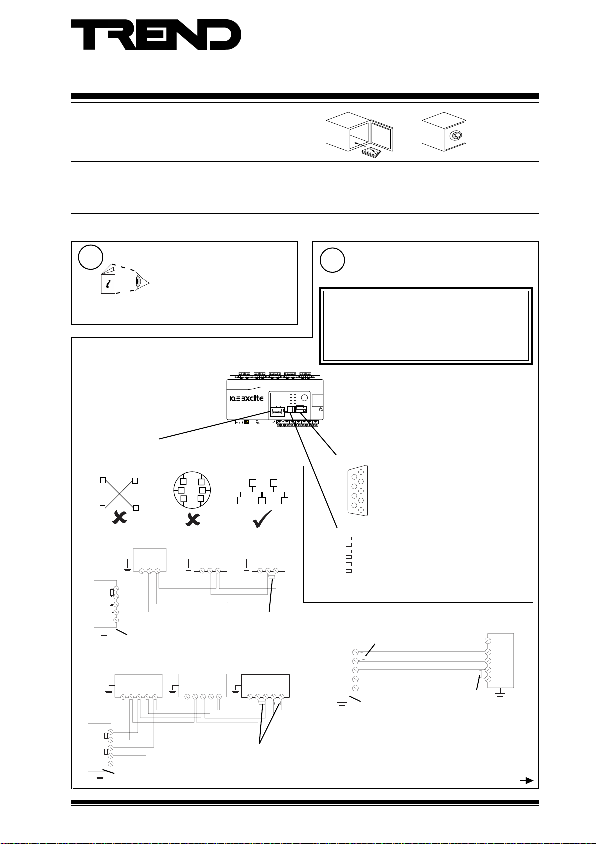
Connect Serial Interface
2
If /SER/.., serial interface auxiliary board, fitted
Note that only one of the RS232 or RS485 connectors can have
a cable connected at any one time in order to comply with Class
B EMC emission standard (EN61000-6-3, residential, commercial,
and light industrial environments).
WARNING: Failure to comply with this requirement will reduce
the unit to Class A (industrial environments); in a domestic
environment the unit may cause radio interference, in which
case the user may be required to take adequate measures.
or RS232
either 9 way D type plug
Note pins 1,6,9 - no connection
If RS485 2 wire
32 devices maximum
0V
0V
AB
AB
0V
AB
IQ3../.../SER/XNC/...
RB
RA
T
B
T
A
0V
120 ohm
terminator
Terminator switch ON
If RS485 4 wire
32 devices maximum
0V
TA TB RA
RB
0V
TA TB RA
RB
0V
TA TB RA
RB
IQ3../.../SER/XNC/...
RB
RA
T
B
T
A
0V
120 ohm
terminators
If the IQ3/XNC/SER controller and its slave units are in the same
cabinet using the same power supply, each device should have
a good physical earth (ground) connection.
Terminator switch ON
IQ3../.../XNC/... Controller/Interface Installation Instructions TG200911 Issue 1/D 03/09/07
or RJ11 socket
Note pin 2 - no connection
Note that only one of the two RS232 connectors can be used at a time
If RS422
IQ3../.../SER/XNC/...
external 100 ohm
terminator
RB
RA
T
B
T
A
0V
Terminator switch OFF
0V
TA
TB
RA
RB
100 ohm
terminator
Step 2 continued over page
1
IQ3../.../XNC/... Installation Instructions
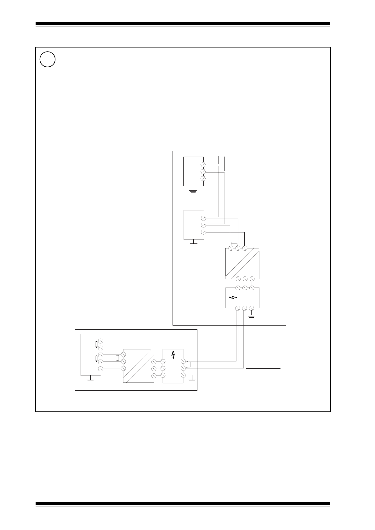
1 Installation - Mounting (continued)
Connect Serial Interface (continued)
2
RS485 2 wire, RS485 4 wire, or RS422 (continued)
If the IQ3/XNC/SER controller and its slave units are in different cabinets or use different power supplies (e.g. different
UPSs), the cabinets should be isolated from each other. If the bus is likely to suffer from surge and grounding problems,
surge protection should be added. The isolator should be connected to the earth (ground) of the nearest device, the 0V
of the isolator and the surge protector should be connected together, and earth (ground) of the surge protector’s exposed
side (e.g. backbone bus) should be connected as directly as possible to the surge ground or earth bond.
Multiple Cabinets
terminate at farend
AB
0V
T
T
0V
AB
0V
0V
B
A
Isolating
Repeater
0V
B
A
0V
AB
B
A
0V
Surge Ground
or Earth Bond
Cabinet B
Surge
Protection
Cabinet A
RB
RA
B
A
Isolating
Repeater
A
B
0V
Surge Ground or Earth Bond
Surge
Protection
A
B
0V
A
A
B
B
0V
0V
Backbone Bus
to more cabinets
terminate at far end
2
IQ3../.../XNC/... Controller/Interface Installation Instructions TG200911 Issue 1/D 03/09/07
Installation Instructions IQ3../.../XNC/...
4 5 6
2
7 8 9
3
10 11 12
4
13 14 15
5
16 17 18
6
19 20 21
7
22 23 24
8
25 26 27
9
28 29 30
10
+ 0
+ 0
+ 0
+ 0
+ 0
+ 0
+ 0
+ 0
+ 0
1 2 3
1
+ 0
34 35 36
12
37 38 39
13
40 41 42
14
A
31 32 33
P
11
43 44 45
15
46 47 48
16
100-240V
OK RX
P 0
P 0
P 0
P 0
P 0
P 0
25 26 27
N
+ 0
1 2 3 4
IQ LAN
T- T+ R- R+
1 2 3 4
T- T+ R- R+
25 26 27
N
+ 0
1 2 3 4
IQ LAN
T- T+ R- R+
1 2 3 4
T- T+ R- R+
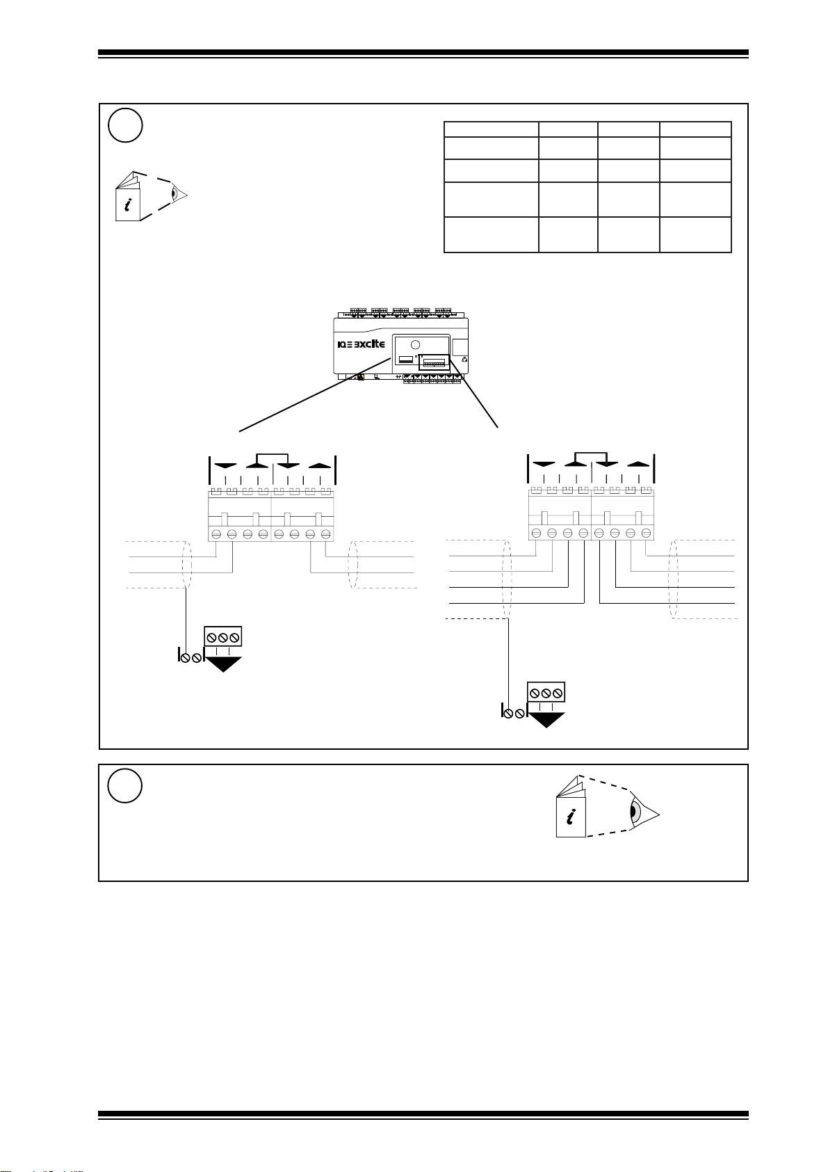
1 Installation - Mounting (continued)
Connect IQ System Current Loop Network
3
If /LAN/.., IQ system current loop Lan auxiliary board,
fitted
Network Engineering Manual, 92-1735
2 off 2 part connectors with 4 screw terminals for 0.5 to 2.5 mm2 cross
section area (14 to 20 AWG) cable
polarity independent
4 5 6
1 2 3
+ 0
Using 2 wire method
T- T+ R- R+
1234
IQ LAN
T- T+ R- R+
1234
+ 0
RX
TX
OK
P 0
24V
24V
0V
Using 4 wire method
elbaCduab6k9duab2k91seriWfo.oN
2819nedleB
7029nedleB
dnerT
002/FH/22/1/1/PT
)1678nedleB(
dnerT
002/FH/22/2/2/PT
)3278nedleB(
T- T+ R- R+
1234
m0001
)sdy0901(
m0001
)sdy0901(
m007
)sdy567(
m005
5(
)sdy54
IQ LAN
T- T+ R- R+
1234
m007
)sdy567(
m005
)sdy545(
m053
)sdy083(
m052
)sdy072(
2
2
2
4
INOUT
earth (ground) screen
to convenient input
channel screen terminal
Continue Installation
4
Install according to IQ3xact installation instructions section 4 step 1 to step 19,
or IQ3xcite installation instructions from section 3 step 12 to section 4 step 20.
INOUT
earth (ground) screen to convenient
input channel screen terminal
IQ3xact Installation Instructions TG200766
IQ3xcite Installation Instructions TG200626
IQ3../.../XNC/... Controller/Interface Installation Instructions TG200911 Issue 1/D 03/09/07
3
 Loading...