

Page 1
Important: Retain these instructions
CONTENTS
Installation Instructions
IQ3xcite
Web Enabled Controller
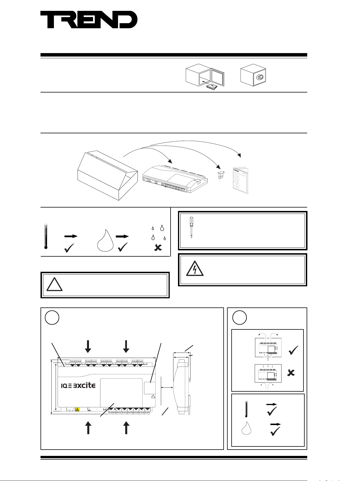
1 Unpacking.......................................................................... 1
2 Storing ................................................................................ 1
3 Installation - Mounting ....................................................... 1
1 Unpacking
2 Storing
-10 °C
(14 °F)
+50 °C
(122 °C)
H2O
0
90 %RH
3 Installation - Mounting
WARNING. If the unit is used in a manner other
than that specified in these instructions, the
!
protection provided by the unit may be impaired.
4 Installation - Configuration ................................................ 7
5 Replacing the Battery ..................................................... 15
6 Disposal ........................................................................... 16
IQ3xcite Installation
Instructions TG200626
It is recommended that the installation should
comply with the HSE Memorandum of Guidance
on Electricity at Work Regulations 1989.
For USA install equipment in accordance with
National Electric Code
DANGER high voltage. No serviceable parts
inside. Other than removing terminal cover,
auxiliary board cover, and lifting I/O bus flap,
DO NOT OPEN UNIT.
1
Dimensions
I/O bus flap
(I/O bus terminator
fitted inside)
28 29 30
10
50 mm
(1.97")
16
P 0
P 0
43 44 451546 47 48
access for cover, auxiliary board
46 mm (1.81")
42 mm (1.65")
terminal cover
150 mm (5.9")
130 mm (5.12")
100-240 V
auxiliary board cover
access for connections
263 mm (10.35")
4 5 6
1 2 3
1
2
+ 0
+ 0
13 14 15
10 11 12
7 8 9
3
4
+ 0
+ 0
+ 0
OK RX
16 17 18
19 20 21
22 23 24
5
6
+ 0
P
24 V
24 V
0 V
8
7
+ 0 + 0 + 0
+ 0
11
12
P 0
P 0
34 35 36
31 32 33
P 0
37 38 39
25 26 27
9
13
14A
P 0
40 41 42
option, and I/O bus flap
access for connections
IQ3xcite Web Enabled Controller Installation Instructions TG200626 Issue 2 21/04/08
2
Requirements
a
4 5 6
16 17 18
13 14 15
19 20 21
1 2 3
25 26 27
22 23 24
10 11 12
7 8 9
28 29 30
3
5
6
8
10
9
1
2
4
7
+ 0
+ 0
+ 0 + 0+ 0
+ 0
+ 0
+ 0
+ 0
+ 0
A
100-240 V
16
15
13
11
12
14A
P 0
P 0
P 0
P 0
P 0
P 0
OK RX
34 35 36
31 32 33
37 38 39
43 44 45
46 47 48
40 41 42
P
24 V
24 V
0 V
4 5 6
16 17 18
13 14 15
19 20 21
1 2 3
22 23 24
25 26 27
10 11 12
7 8 9
28 29 30
3
5
6
8
9
10
1
2
4
7
+ 0
+ 0
+ 0
+ 0
+ 0
+ 0
+ 0
+ 0
+ 0
+ 0
A
100-240 V
16
13
11
12
14A
P 0
P 0
P 0
P 0
P 0
P 0
OK RX
34 35 36
31 32 33
37 38 39
43 44 451546 47 48
40 41 42
P
24 V
24 V
0 V
b
0 °C
(32 °F)
0 %RH
H2O
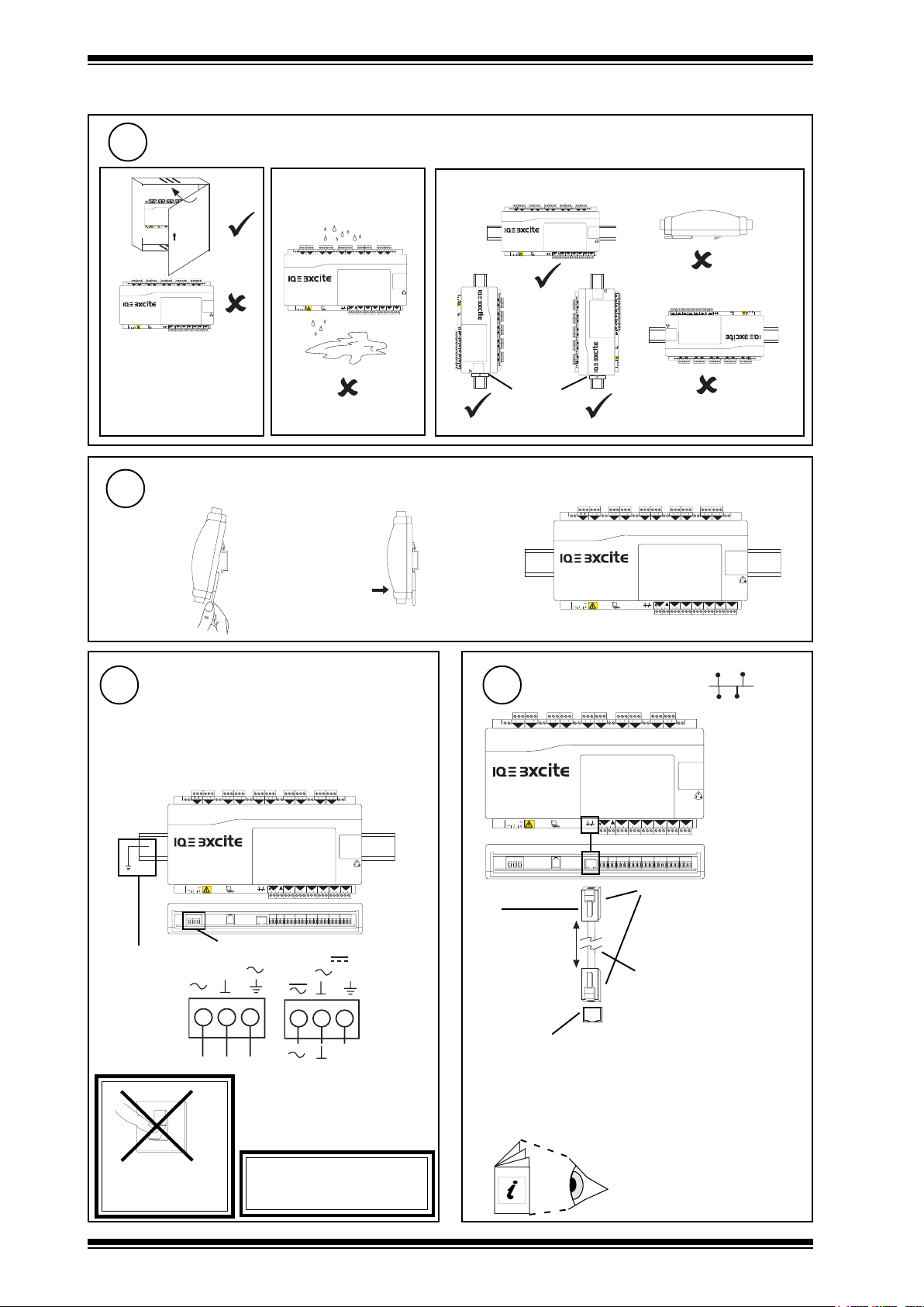
Protection IP20, NEMA1
+45 °C
(113 °F)
90 %RH
1
Page 2
IQ3xcite Installation Instructions
0
3 Installation - Mounting (continued)
2
Requirements (continued)
c
4 5 6
16 17 18
1 2 3
13 14 15
19 20 21
22 23 24
25 26 27
10 11 12
7 8 9
28 29 30
3
5
6
8
9
10
1
2
4
7
+ 0
+ 0
+ 0 + 0+ 0
+ 0
+ 0
+ 0
+ 0
+ 0
A
100-240 V
16
13
11
12
14A
P 0
P 0
P 0
P 0
P 0
P 0
OK RX
34 35 36
37 38 39
31 32 33
43 44 451546 47 48
40 41 42
P
24 V
24 V
0 V
4 5 6
16 17 18
13 14 15
19 20 21
1 2 3
1
+ 0
100-240 V
22 23 24
25 26 27
10 11 12
7 8 9
3
2
+ 0
+ 0
28 29 30
5
6
10
8
9
4
7
+ 0
+ 0 + 0+ 0
+ 0
+ 0
+ 0
16
15
13
11
12
14A
P 0
P 0
P 0
P 0
P 0
P 0
OK RX
34 35 36
31 32 33
37 38 39
43 44 45
46 47 48
40 41 42
P
24 V
24 V
0 V
IQ3XCITE/.../USA/UL/../24 is
UL rated as ‘UL916 listed
open energy management
equipment’.
Mounting
3
a
d
4 5 6
16 17 18
13 14 15
1 2 3
1
2
+ 0
+ 0
100-240 V
19 20 21
22 23 24
10 11 12
7 8 9
3
4
+ 0
+ 0
25 26 27
28 29 30
5
6
8
9
10
7
+ 0
+ 0 + 0 + 0
+ 0
+ 0
16
13
11
12
14A
P 0
P 0
P 0
P 0
P 0
OK RX
P 0
34 35 36
31 32 33
37 38 39
43 44 451546 47 48
40 41 42
P
24 V
24 V
0 V
e
4 5 6
16 17 18
13 14 15
19 20 21
1 2 3
1
+ 0
100-240 V
100-240 V
+ 0
1 2 3
1
4 5 6
+ 0
2
+ 0
7 8 9
3
10 11 12
+ 0
4
13 14 15
+ 0
RX OK
5
16 17 18
+ 0
6
24 V
0 V
24 V
P
31 32 33
P 0
19 20 21
+ 0
11
7
34 35 36
P 0
22 23 24
+ 0 + 0+ 0
12
8
37 38 39
P 0
13
25 26 27
40 41 42
P 0
9
14A
28 29 30
43 44 45
P 0
10
15
46 47 48
P 0
16
22 23 24
25 26 27
10 11 12
7 8 9
3
2
+ 0
+ 0
28 29 30
5
6
8
9
10
4
7
+ 0 + 0+ 0
+ 0
+ 0
+ 0
+ 0
16
13
11
12
14A
P 0
P 0
P 0
P 0
P 0
P 0
OK RX
34 35 36
31 32 33
37 38 39
43 44 451546 47 48
40 41 42
P
24 V
24 V
0 V
16
P 0
46 47 48
15
10
P 0
43 44 45
28 29 30
14A
9
P 0
40 41 42
25 26 27
13
P 0
37 38 39
8
12
+ 0 + 0+ 0
22 23 24
P 0
34 35 36
7
11
+ 0
19 20 21
P 0
31 32 33
P
24 V
0 V
24 V
6
+ 0
16 17 18
5
RX OK
+ 0
13 14 15
4
+ 0
10 11 12
3
7 8 9
+ 0
2
+ 0
4 5 6
1
+ 0
1 2 3
100-240 V
16
P 0
40 41 42
43 44 451546 47 48
P 0
P 0
14A
9
10
28 29 30
25 26 27
0 V
24 V
24 V
P
37 38 39
31 32 33
34 35 36
OK RX
P 0
P 0
P 0
12
11
13
+ 0
+ 0 + 0+ 0
7
8
22 23 24
19 20 21
100-240 V
+ 0
+ 0
+ 0
+ 0
+ 0
+ 0
2
4
1
3
5
6
7 8 9
10 11 12
1 2 3
13 14 15
4 5 6
16 17 18
DIN rail
end stop
4 5 6
1 2 3
1
2
+ 0
b
c
+ 0
16 17 18
13 14 15
19 20 21
22 23 24
6
7
+ 0 + 0 + 0
+ 0
25 26 27
28 29 30
8
9
10
10 11 12
7 8 9
3
5
4
+ 0
+ 0
+ 0
+ 0
4
/100-240 100 to 240 Vac ±10% 50/60 Hz at 56 VA max
(A 240 Vac, 1 A, switch or circuit breaker must be included in the supply
Connect Power
to the unit and be in close proximity to it, and must be clearly marked
as the disconnecting device for the unit.)
/24 24 to 60 Vdc (36 Vdc maximum for /UL
versions), 24 Vac 50/60 Hz, at 40 VA max.
ensure DIN rail is
earthed (grounded)
4 5 6
1 2 3
1
2
+ 0
+ 0
100-240 V
/100-240
100-240 V
16 17 18
13 14 15
19 20 21
22 23 24
6
24 V
P
24 V
0 V
8
7
+ 0 + 0 + 0
+ 0
11
12
P 0
P 0
34 35 36
31 32 33
/24
24-60 V
24 V
25 26 27
28 29 30
9
10
16
13
14A
P 0
P 0
P 0
P 0
37 38 39
43 44 451546 47 48
40 41 42
10 11 12
7 8 9
3
5
4
+ 0
+ 0
+ 0
+ 0
OK RX
(36 Vdc
maximum
for /UL)
E
24 Vac
24 to 36 Vdc
Terminal size 0.5 to 2.5 mm
V
2
(14 to 20 AWG)
O
I
EN61010:2001
INSTALLATION CATEGORY III
(fixed installations)
5
Connect to Ethernet
If required
4 5 6
1 2 3
10 11 12
7 8 9
3
1
2
+ 0
+ 0
+ 0
+ 0
100-240 V
Standard Ethernet
100-240 V
16 17 18
13 14 15
19 20 21
5
6
4
7
+ 0
+ 0
+ 0
11
P 0
OK RX
31 32 33
P
24 V
24 V
0 V
OK RX
24 V
0 V
22 23 24
25 26 27
8
9
+ 0 + 0 + 0
13
12
14A
P 0
P 0
P 0
34 35 36
37 38 39
40 41 42
11
P 0
P 0
34 35 36
31 32 33
P
24 V
28 29 30
10
15
P 0
P 0
43 44 45
46 47 48
RJ45
16
13
12
14A
P 0
P 0
P 0
P 0
37 38 39
43 44 451546 47 48
40 41 42
16
cable
100 m
(max)
Cat 5e twisted pair
Ethernet hub or switch
e.g EDS205 5 port unmanaged switch (available from
IQ system supplier)
Note that a single device may be connected directly to the IQ3
from Ethernet using the standard Ethernet cable plus an XCITE/XA
crossover adaptor, see section 4 step13
DO NOT APPLY
POWER
2
This apparatus must be earthed
(grounded) (through power connector)
WARNING:
IQ3xcite Web Enabled Controller Installation Instructions TG200626 Issue 2 21/04/08
IQ System Ethernet Products
Engineering Guide TE200369
Page 3
Installation Instructions IQ3xcite
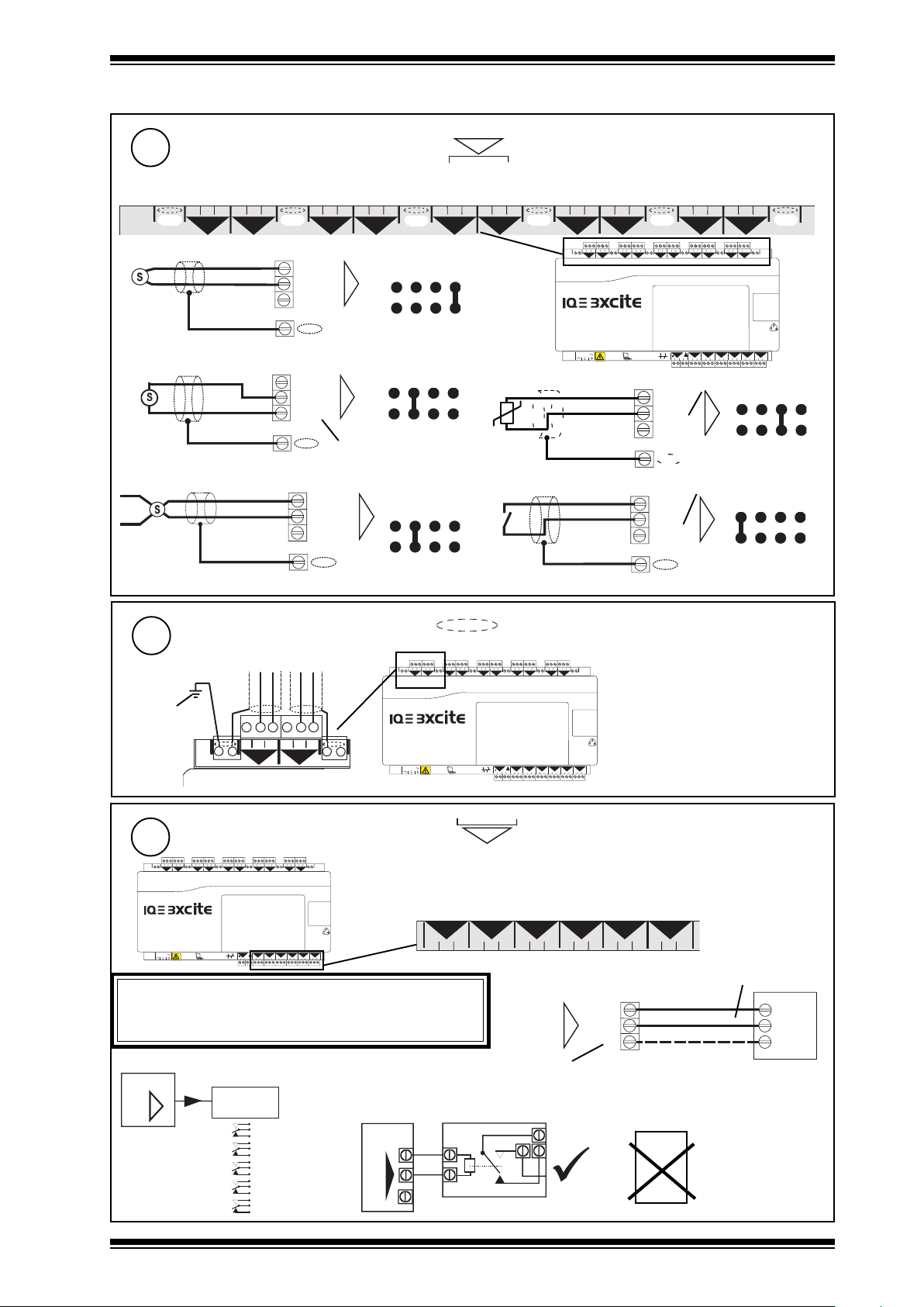
V
3 Installation - Mounting (continued)
6
Connect Inputs (channels 1 to 10)
N
EN61010:2001 MEASUREMENT CATEGORY 1. Separate from 230 Vac input power supply by double or reinforced insulation
TP/1/1/22/HF/200 (Belden 8761) cable recommended for all inputs. Cable size 0.5 to 2.5 mm2 (14 to 20 AWG), Cu only
1 2 3
+ 0
4 5 6
1
2
+ 0
7 8 9
+ 0
Voltage input
0 (0 V)
N (in)
(0 to 10V)
+ (+24V)
Current input (loop powered)
®
(0 to 20 mA)
SIG
1
0 (0 V)
N (in)
+ (+24V)
Current input (external powered)
0V
SIG
®1 (0 to 20 mA)
0 (0 V)
N (in)
+ (+24V)
10 11 12
3
+ 0
N
N
(20 to 36 V)
N
4
linking
linking
I
linking
I
13 14 15
5
+ 0
V
16 17 18
6
+ 0
Thermistor input
0V
Digital input
19 20 21
7
+ 0
100-240 V
22 23 24
8
+ 0 + 0 + 0
4 5 6
1 2 3
+ 0
10 11 12
7 8 9
3
1
2
+ 0
+ 0
+ 0
25 26 27
9
16 17 18
13 14 15
19 20 21
22 23 24
5
6
4
7
+ 0
+ 0 + 0 + 0
+ 0
+ 0
11
P 0
P 0
OK RX
34 35 36
31 32 33
P
24 V
24 V
0 V
5 V bridge supply
0 (0 V)
N (in)
+ (+24V)
5 V supply
0 (0 V)
N (in)
N
+ (+24V)
28 29 30
10
25 26 27
28 29 30
10
8
9
16
15
13
12
14A
P 0
P 0
P 0
P 0
37 38 39
43 44 45
46 47 48
40 41 42
linking
N
T
linking
D
Note that setting input links is described in Installation Instructions - section 4 step 6
Segregate Screen Earth (Ground)
7
separate
earth (ground)
connection
8
If external supply is used to supply P input terminal, note whether
P bus is 24 Vac or 24 Vdc and only connect appropriate
output devices to P output terminals
Additional Relay Modules
IQ3
if required to segregate screen earth (ground) from controller input power supply earth (ground)
4 5 6
1 2 3
1
2
+ 0
+ 0
4 5 6
1 2 3
+ 0
2
1
+ 0
100-240 V
Connect Outputs (channels 11 to 16)
4 5 6
1 2 3
1
2
+ 0
+ 0
100-240 V
16 17 18
13 14 15
19 20 21
22 23 24
10 11 12
7 8 9
3
5
4
+ 0
+ 0
+ 0
+ 0
OK RX
25 26 27
7
+ 0
11
P 0
31 32 33
P
8
9
+ 0 + 0 + 0
13
12
14A
P 0
P 0
P 0
34 35 36
37 38 39
40 41 42
28 29 30
6
24 V
24 V
0 V
WARNING
Relay
N
SRMV =
2SRM =
2RM =
3RM =
6RM =
Module
nRM
x 1
x 2
x 2
x 3
x 6
(R/L, H/L)
(HCM/TRM)
EN61010:2001 MEASUREMENT CATEGORY 1. Separate from 230 Vac input power
10
supply by double or reinforced insulation
TP/1/1/22/HF/200 (Belden 8761) cable recommended for voltage outputs
If screened cable is used, terminate screen to earth (ground) at one end
P 0
16
15
P 0
P 0
43 44 45
46 47 48
31 32 33
Cable size 0.5 to 2.5 mm2 (14 to 20 AWG), Cu only
e.g.
IQ3
0
P
10 11 12
7 8 9
3
+ 0
+ 0
11
SRMV
16 17 18
13 14 15
19 20 21
22 23 24
25 26 27
5
6
4
+ 0
+ 0
8
7
+ 0 + 0 + 0
+ 0
28 29 30
10
9
Note that screen earth (ground) link must
be cut (see section 4 step 7)
16
15
13
11
12
14A
P 0
P 0
P 0
P 0
P 0
OK RX
34 35 36
31 32 33
P
24 V
24 V
0 V
P 0
37 38 39
43 44 45
46 47 48
40 41 42
N
13
12
P 0
34 35 36
P 0
37 38 39
14
P 0
40 41 42
N
(out) N
P 0
43 44 451546 47 48
0
(0 to 10 Vdc, <=20 mA)
P
If P terminal used, P input terminal must be
connected as in step 9 below
SRMAC
16
P 0
optional
(0 V)
(+24 V)
Analogue
outputs are
not suitable
for ac
relays
I<=20 mA
LOAD
IQ3xcite Web Enabled Controller Installation Instructions TG200626 Issue 2 21/04/08
3
Page 4
IQ3xcite Installation Instructions
A
A
31 32 33
P
11
P 0
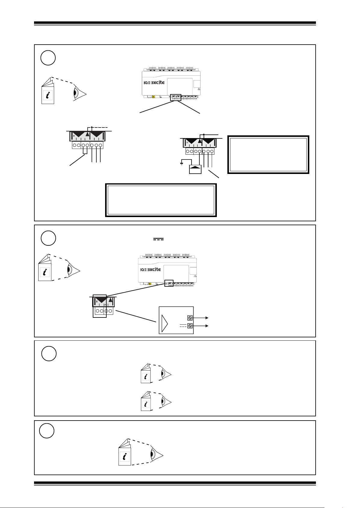
3 Installation - Mounting (continued)
9
either use IQ3xcite 24 Vdc auxiliary supply
Fit external link
if P terminal used (see step 8 above)
Check IQ3xcite 24 Vdc
combined and auxiliary
output current availability:
IQ3 Configuration
Manual TE200768
A
11
A
P 0
31 32 33
P
24 V
24 V
0 V
If external supply is used, note whether P bus
is 24 Vac or 24 Vdc and only connect appropriate
output devices to P output terminals
Connect Output Power (P)
4 5 6
1 2 3
10 11 12
7 8 9
3
1
2
+ 0
+ 0
+ 0
+ 0
100-240 V
WARNING
16 17 18
13 14 15
19 20 21
22 23 24
25 26 27
5
4
+ 0
+ 0
28 29 30
6
10
8
9
7
+ 0 + 0+ 0
+ 0
terminal size 0.5 to 2.5 mm2 (14 to 20 AWG)
EN61010:2001 MEASUREMENT CATEGORY 1
Separate from 230 Vac input power supply by double or
16
15
13
11
12
14A
P 0
P 0
P 0
P 0
P 0
OK RX
P
24 V
24 V
0 V
P 0
34 35 36
31 32 33
37 38 39
43 44 45
46 47 48
40 41 42
reinforced insulation
or use 24 Vdc or 24 Vac external supply
Connect external supply (no external link)
24 V
24 V
0V
External PSU must be dedicated
to I/O channel use, and comply
with relevant EMC and safety
PSU
standards
External PSU with
isolated output
WARNING
10
Connect Auxiliary Supply (24 V )
Check IQ3xcite 24 Vdc
combined and auxiliary
output current
availability:
IQ3 Configuration
Manual TE200768
A
A
P
24 V
24 V
0 V
Install Auxiliary Board
11
for IQ3../.../LAN/...
for IQ3../.../XNC/.., including
IQ3../.../LAN/XNC/..., IQ3../.../SER/XNC/...
if required
4 5 6
1 2 3
1
+ 0
+ 0
16 17 18
13 14 15
19 20 21
22 23 24
10 11 12
7 8 9
3
2
4
+ 0
+ 0
+ 0
25 26 27
5
28 29 30
6
10
8
9
7
+ 0
+ 0 + 0+ 0
+ 0
terminal size 0.5 to 2.5 mm2 (14 to 20 AWG)
EN61010:2001 MEASUREMENT CATEGORY 1
100-240 V
13
11
12
P 0
P 0
P 0
OK RX
34 35 36
31 32 33
37 38 39
P
24 V
24 V
0 V
Separate from 230 Vac input supply by double or
16
15
14A
P 0
P 0
P 0
43 44 45
46 47 48
40 41 42
reinforced insulation
Note that the 24 Vdc supply is normally about 22 V
IQ3
0 V
A
24 V
and drops to about 20.7 V at full load.
Imax = 150 mA(including current to P bus,
- see step 9 above)
if fitted (for battery board, BBC/UK, see section 4 step 9)
IQ3../.../LAN/... Installation Instructions TG200916 section 1
IQ3../.../XNC/... Installation Instructions TG200911 section 1
Install I/O Modules
12
if required
(IQ3XCITE/96/.. and /128.. only)
XCITE Standard I/O Modules Installation Instructions TG200627
Installation, section 3 steps 1 to 11 only
4
IQ3xcite Web Enabled Controller Installation Instructions TG200626 Issue 2 21/04/08
Page 5
Installation Instructions IQ3xcite
3 Installation - Mounting (continued)
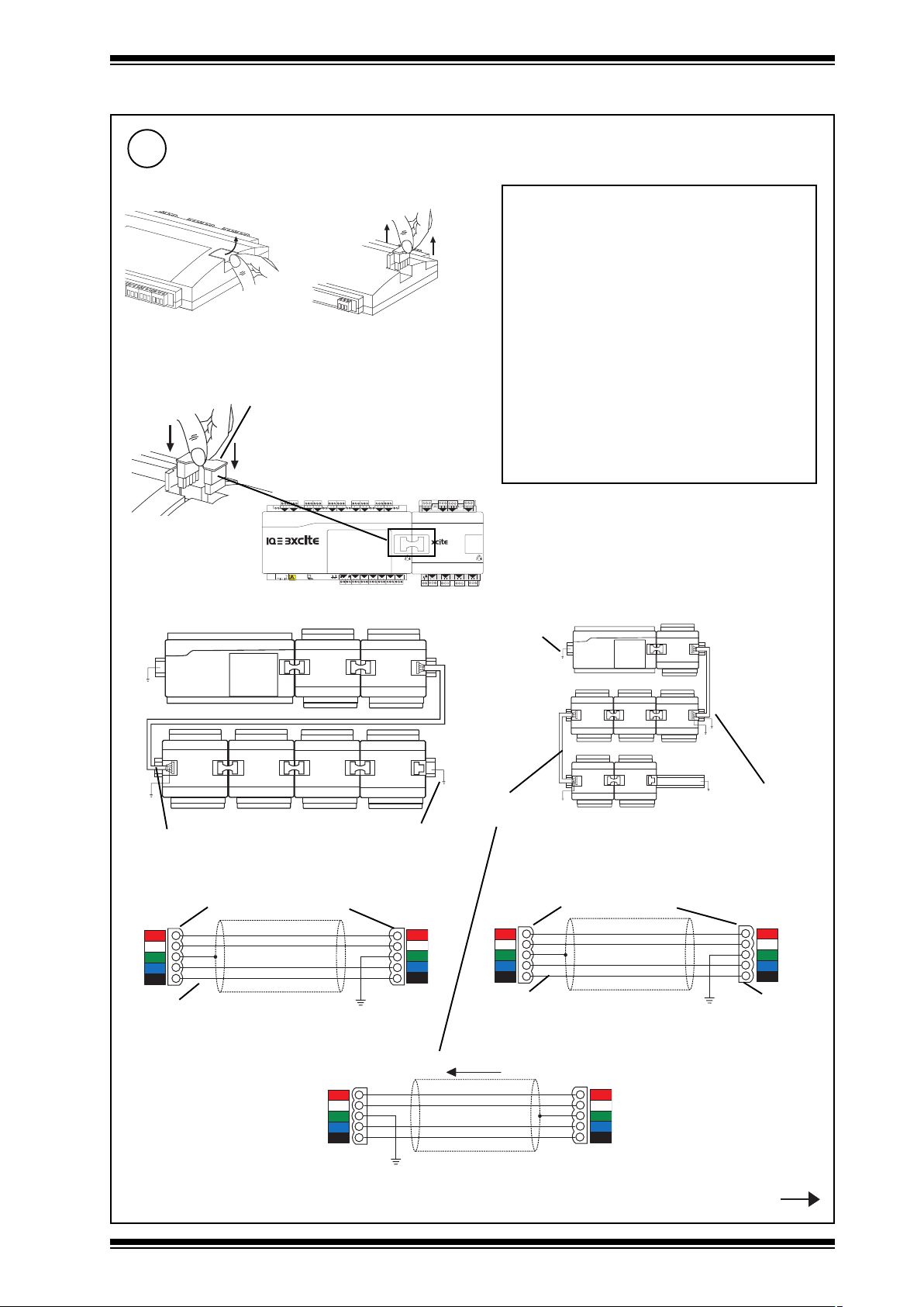
Connect I/O Bus
if required
13
a
Open Flap
either use XCITE/IC interconnector (supplied with I/O module)
c
(IQ3XCITE/96/.. and /128.. only)
b Remove Terminator
XCITE/IC interconnector (supplied)
(XCITE/IC/5, pack of 5 available separately)
4 5 6
1 2 3
1
+ 0
+ 0
100-240 V
16 17 18
13 14 15
19 20 21
22 23 24
10 11 12
7 8 9
3
2
4
+ 0
+ 0
25 26 27
28 29 30
5
6
8
7
+ 0
+ 0 + 0+ 0
+ 0
+ 0
13
11
12
P 0
P 0
P 0
OK RX
34 35 36
31 32 33
37 38 39
P
24 V
24 V
0 V
1 2 3
10
9
P 0
40 41 42
1
+ 0
16
15
14A
5
P 0
P 0
P 0
43 44 45
46 47 48
P
13 14 15
24 V
• A maximum of 15 I/O modules can be
connected.
• A maximum of 96 or 128 points (16 points in
the IQ3xcite and 80 or 112 expansion points)
can be used.
• The controller and its I/O modules are to be
fitted inside enclosures.
• No spurs are allowed on the I/O bus.
• If a single earth (ground) screened and bonded
contiguous metal enclosure is used, then
total I/O bus length can be up to 30 m (includes
use of multisection panels e.g. Form 4 enclosures)
If any other type of enclosure is used, or I/O
bus runs between enclosures, then total I/O
bus cable length can be up to 10 m.
(For cable length calculation, rigid interconnectors
can be ignored)
•Multiple enclosures must be earthed
(grounded) to a common earth (ground) point
(according to latest IEE Regs).
4 5 6
7 8 9
10 11 12
3
2
4
+ 0
+ 0
+ 0
6
7
8
P 0
P 0
P 0
22 23 24
16 17 18
19 20 21
or wire special cable using XCITE/CC connectors and Belden 3084A cable
DIN rails must
be earthed
(grounded)
cable type B
(left to left)
cable type A
DIN rails must be
earthed (grounded)
XCITE/CC connectors
Order separately (XCITE/CC/10, pack of 10)
+24 Vdc
1
Data Hi
2
Ground
3
Data Lo
4
0 V
5
Red
White
Blue
Black
Belden 3084A cable
cable type A
+24 Vdc
Data Hi
Ground
Data Lo
0 V
5
4
3
2
1
+24 Vdc
1
Data Hi
2
Ground
3
Data Lo
4
0 V
5
Belden 3084A cable
cable type B (right to right)
cable type B
(right to right)
XCITE/CC connectors
Order separately (XCITE/CC/10, pack of 10)
Red
White
Blue
Black
+24 Vdc
Data Hi
Ground
Data Lo
0 V
1
2
3
4
5
connector rotated
through 180 °
Signal direction
+24 Vdc
5
Data Hi
4
Ground
3
Data Lo
2
0 V
1
Red
White
Blue
Black
+24 Vdc
Data Hi
Ground
Data Lo
0 V
cable type B (left to left)
IQ3xcite Web Enabled Controller Installation Instructions TG200626 Issue 2 21/04/08
5
4
3
2
1
Step 13 continued
5
Page 6

IQ3xcite Installation Instructions
L+
L+
LL-
L
N
DC
ADJ.
IN
L+
L+
LL-
L
N
DC
ADJ.
IN
3 Installation - Mounting (continued)
Connect I/O Bus (continued)
13
c
continued
Fully screened and bonded contiguous multi section cabinet
terminator
type B
PSR
PSR
type A
type B
An additional 24 Vdc ±15% power supply must be used to supply the IO modules if:
• There are more than 6 I/O modules (excluding /8AO, /4AO, /16DI, /8DI, /8DI/8TI, /8DO/HOA, /4DO/HOA, and /8DO
serial number >= M3D8 C0 508 1136, /4DO serial number >=M3D4 C0 508 012; which do not need to be included
in the count).
or • The main controller 24 Vdc combined supply would be overloaded
Check IQ3xcite 24 Vdc
combined supply
WARNING: External PSU must have isolated output and
comply with relevant EMC and safety standards
current availability
IQ3 Configuration Manual TE200768
Note that the maximum current that can be flow through an I/O module using the 24 Vdc and 0 V terminals, from one module to the
next, is 2.5 A.
External PSU with isolated output
External PSU with isolated output
XCITE/PCON/1000, 1 metre cable (type A)
available, order separately
+24 Vdc
1
Data Hi
2
Ground Ground
3
Data Lo
4
0 V
5
White
Blue
Black
Black
24 Vdc
PSU
Red
+24 Vdc
Data Hi
Data Lo
0 V
XCITE/PCON/50, for adjacent
modules available, order separately
(modules separated by 10 mm)
5
4
3
2
1
24 Vdc
PSU
Black
Red
+24 Vdc
1
Data Hi
2
Ground
3
Data Lo
4
0 V
5
White
Blue
Black
+24 Vdc
Data Hi
Ground
Data Lo
0 V
Trend can supply the PSR range of DIN rail mounted auxiliary power supplies (e.g. 1.3 A or 2.5 A). They have isolated outputs.
5
4
3
2
1
230 Vac input
power supply
d
14
Terminate I/O Bus
Open flap
L
IN
N
PSR
DC
ADJ.
L+
L+
LL-
Red
Black
PSR connection to left side
Close flap
Plug in terminator (supplied)
ba
Blue
Black
Black
Blue
White
5
4
3
2
1
White
1
2
3
4
5
Red
Black
PSR connection to right side
on furthest I/O module or on controller if no I/O modules
XCITE/TERM terminator
(supplied with IQ3xcite)
(XCITE/TERM/5,
pack of 5 available separately)
DC
ADJ.
c
L
N
PSR
L+
L+
LL-
IN
230 Vac input
power supply
Close flap
6
IQ3xcite Web Enabled Controller Installation Instructions TG200626 Issue 2 21/04/08
Page 7

Installation Instructions IQ3xcite
4 Installation - Configuration
Switch Off
1
O
I
Open Panel
4 5 6
16 17 18
13 14 15
19 20 21
1 2 3
25 26 27
10 11 12
22 23 24
7 8 9
28 29 30
3
5
6
8
9
10
1
2
4
7
+ 0
+ 0 + 0 + 0
+ 0
+ 0
+ 0
+ 0
+ 0
3
WARNING: Opening the panel may expose
dangerous voltages.
+ 0
A
100-240 V
13
11
12
14A
P 0
P 0
P 0
P 0
P 0
OK RX
34 35 36
31 32 33
37 38 39
43 44 451546 47 48
40 41 42
P
24 V
24 V
0 V
417-IEC-5036
16
P 0
Isolate I/O
2
4 5 6
1 2 3
1
+ 0
+ 0
100-240 V
WARNING: The connecting leads may be
connected to supplies. Isolate before touching.
Disconnect I/O
16 17 18
13 14 15
19 20 21
22 23 24
10 11 12
7 8 9
3
2
4
+ 0
+ 0
25 26 27
5
+ 0
28 29 30
6
10
8
9
7
+ 0
+ 0 + 0+ 0
+ 0
also isolate I/O of any
adjacent I/O modules
16
15
13
11
12
14A
P 0
P 0
P 0
P 0
P 0
OK RX
P
24 V
24 V
0 V
P 0
34 35 36
31 32 33
37 38 39
43 44 45
46 47 48
40 41 42
4
4 5 6
1 2 3
1
2
+ 0
+ 0
100-240 V
also disconnect I/O of any I/O modules
16 17 18
13 14 15
19 20 21
22 23 24
10 11 12
7 8 9
5
3
4
+ 0
+ 0
+ 0
+ 0
OK RX
25 26 27
6
8
9
7
+ 0
+ 0
+ 0
13
11
12
14A
P 0
P 0
P 0
P 0
34 35 36
31 32 33
37 38 39
40 41 42
P
24 V
24 V
0 V
28 29 30
10
+ 0
P 0
43 44 451546 47 48
O
I
O
I
16
P 0
Remove Cover
5
a
b
4 5 6
1 2 3
+ 0
100-240 V
13 14 15
10 11 12
7 8 9
5
3
1
2
4
+ 0
+ 0
+ 0
+ 0
OK RX
4 5 6
1 2 3
1
+ 0
+ 0
100-240 V
16 17 18
19 20 21
22 23 24
25 26 27
6
8
9
7
+ 0
+ 0 + 0+ 0
+ 0
13
11
12
14A
P 0
P 0
P 0
P 0
34 35 36
31 32 33
37 38 39
40 41 42
P
24 V
24 V
0 V
Cut Screen Earth (Ground) Link
7
if screen earth (ground) segregated from
controller input supply earth (ground)
- see section 3, step 7)
2
28 29 30
10
P 0
43 44 451546 47 48
16 17 18
13 14 15
19 20 21
22 23 24
10 11 12
7 8 9
5
3
4
+ 0
+ 0
+ 0
OK RX
25 26 27
6
+ 0
28 29 30
10
8
9
7
+ 0 + 0 + 0
+ 0
13
11
12
14A
P 0
P 0
P 0
P 0
P 0
P 0
34 35 36
31 32 33
37 38 39
43 44 451546 47 48
40 41 42
P
24 V
24 V
0 V
c
16
P 0
100-240 V
Select Input Channel Types
6
16
16
13
11
12
14A
P 0
P 0
P 0
P 0
P 0
OK RX
P
24 V
24 V
0 V
P 0
34 35 36
31 32 33
37 38 39
43 44 451546 47 48
40 41 42
D (digital)
either loop powered (IL), or external powered (IX)
Replace Cover
100-240 V
I (current)
OK RX
24 V
24 V
0 V
(thermistor) T
11
12
P 0
P 0
34 35 36
31 32 33
P
16
13
14A
P 0
P 0
P 0
P 0
37 38 39
43 44 451546 47 48
40 41 42
(voltage) V
8
4 5 6
1 2 3
7 8 9
1
2
+ 0
+ 0
+ 0
16 17 18
13 14 15
19 20 21
22 23 24
10 11 12
5
3
6
4
+ 0
+ 0
+ 0
25 26 27
28 29 30
8
9
7
+ 0
10
+ 0
+ 0
+ 0
100-240 V
11
P 0
P 0
OK RX
34 35 36
31 32 33
P
24 V
24 V
0 V
16
13
12
14A
P 0
P 0
P 0
P 0
37 38 39
43 44 451546 47 48
40 41 42
screen earth (ground) link
IQ3xcite Web Enabled Controller Installation Instructions TG200626 Issue 2 21/04/08
100-240 V
11
12
P 0
P 0
OK RX
34 35 36
31 32 33
P
24 V
24 V
0 V
16
13
14A
P 0
P 0
P 0
P 0
37 38 39
43 44 451546 47 48
40 41 42
7
Page 8

IQ3xcite Installation Instructions
4 5 6
2
7 8 9
3
10 11 12
4
13 14 15
5
16 17 18
6
19 20 21
7
22 23 24
8
25 26 27
9
28 29 30
10
+ 0
+ 0
+ 0
+ 0 + 0 + 0
+ 0
+ 0
+ 0
1 2 3
1
+ 0
0 V
24 V
24 V
34 35 36
12
37 38 39
13
40 41 42
14A
31 32 33
P
11
43 44 45
15
46 47 48
16
100-240 V
OK RX
P 0
P 0
P 0
P 0
P 0
P 0
24 V
P
13 14 15
5
P 0
16 17 18
6
P 0
19 20 21
7
P 0
22 23 24
8
P 0
1 2 3
1
+ 0
4 5 6
2
+ 0
7 8 9
3
+ 0
10 11 12
4
+ 0
24 V
P
13 14 15
5
P 0
16 17 18
6
P 0
19 20 21
7
P 0
22 23 24
8
P 0
1 2 3
1
+ 0
4 5 6
2
+ 0
7 8 9
3
+ 0
10 11 12
4
+ 0
CR 2032
4 Installation - Configuration (continued)
Fit Battery Option
9
If /LAN/ or /SER/ option fitted see separate installation instructions:
if required (to support clock for several years e.g. for Timemaster)
for IQ3xcite/../LAN/... see IQ3xcite/../LAN/... installation instructions TG200916
for IQ3xcite/../LAN/XNC/... or IQ3/../SER/XNC/.. see IQ3xcite/../XNC/... installation instructions TG200911
a
Remove auxiliary board cover
c
apply board to plate
XCITE/BBC
battery option board (order separately)
Replace auxiliary board cover
f
d
press board home
apply plate
b
plate supplied with
e
insert battery
XCITE/BBC
battery supplied with XCITE/BBC
Switch On
10
CR 2032
Check Controller
11
1 2 3
1
+ 0
100-240 V
a (watchdog)
(red)
b (power)
(green)
O
I
c (I/O bus)
4 5 6
2
+ 0
16 17 18
13 14 15
19 20 21
22 23 24
10 11 12
7 8 9
3
5
4
+ 0
+ 0
+ 0
+ 0
25 26 27
7
+ 0 + 0 + 0
+ 0
28 29 30
10
8
9
6
(red)
(IQ3XCITE/96/.. and /128 only)
Check I/O connection for short circuits,
Data Hi or Data Lo to either power line.
Check for faulty I/O module
disconnect
4 5 6
1 2 3
7 8 9
15
13
11
12
14A
P 0
P 0
P 0
P 0
OK RX
24 V
P 0
34 35 36
31 32 33
37 38 39
43 44 45
40 41 42
P
24 V
0 V
IQ Faulty (software or
strategy)
16
P 0
46 47 48
move terminator
Switch off power
Disconnect farthest I/O module
10 11 12
3
1
2
4
+ 0
+ 0
+ 0
+ 0
6
7
5
8
P 0
P 0
P 0
P 0
22 23 24
16 17 18
19 20 21
P
13 14 15
24 V
Move terminator
Switch on power
power supply fail
return to supplier
Check (I/O) light
Repeat to isolate faulty module - replace module or connection
8
IQ3xcite Web Enabled Controller Installation Instructions TG200626 Issue 2 21/04/08
Page 9

Installation Instructions IQ3xcite
4 Installation - Configuration (continued)
12
Check Ethernet
4 5 6
1 2 3
1
2
+ 0
+ 0
13 14 15
10 11 12
7 8 9
3
5
4
+ 0
+ 0
+ 0
16 17 18
19 20 21
22 23 24
25 26 27
8
9
+ 0 + 0 + 0
28 29 30
10
6
7
+ 0
+ 0
a OK (green)
100-240 V
OK RX
11
12
P 0
P 0
P 0
34 35 36
31 32 33
37 38 39
P
24 V
24 V
0 V
16
15
13
14A
P 0
P 0
P 0
43 44 45
46 47 48
40 41 42
Check Ethernet
Connect IPTool
13
The IP addressing may be set up automatically or manually as explained in step 17 overleaf.
To discover the IP addressing, or to change it, use IPTool.
Note that in order to use IPTool for this, the host PC must have its own IP addressing set up correctly.
either use Ethernet connection
SET Manual TE200147
IPTool Manual TE200638
IQ3 Reset Applet Manual
Router
IPTool (and SET v6.2)
standard Ethernet connection
see section 3 step 5
Router
b RX (yellow)
TE200767
IQ3
or use local PC (Ethernet) connection; it can be either to adjacent Ethernet hub using standard cable only, or directly
to IQ3 using standard cable and crossover adaptor, XCITE/XA.
IPTool (and SET v6.2)
100-240 V
OK RX
RJ45
XCITE/XA crossover adaptor
standard Ethernet cable - see section 3 step 5
order separately (XCITE/XA/5 pack of 5)
Note that if communications fail completely the IQ3 can be reset using the SET Reset applet
DHCP Server
14
If the IP address settings (IP address, subnet mask, default router, WINS and DNS servers’ addresses) are to be supplied
by a DHCP server, ensure one is installed on the Ethernet segment to which the IQ3 is connected.
Note that on a mutiple segment system a single DHCP server may be used providing it has connections to each segment
i.e. mutiple connections.
The DHCP server must be capable of downloading either or both (as appropriate - see steps 15 and 16) the WINS server
address and the DNS server address.
IQ3xcite Web Enabled Controller Installation Instructions TG200626 Issue 2 21/04/08
9
Page 10

IQ3xcite Installation Instructions
4 Installation - Configuration (continued)
WINS Server
15
If host names are being used for IP addressing across
a router, then a WINS server must be installed on the
system.
Configure Addressing Details with IPTool
17
DNS Server
16
If email alarms are being sent, and the email server
address is identified by internet domain name, then a
DNS server must be installed on the system.
IQ3 Configuration Manual TE200768
IPTool Manual TE200638
The IQ3’s IP addressing information can be set up automatically (Obtain Automatically) or manually (Enter Manually). When
set for automatic IP addressing, the IQ3 will default to link/local mode where it autonegotiates its IP address with other devices
on its Ethernet segment, but if a DHCP server is operating on its segment, the server will set up the IP addressing. Alternatively
the settings can be specified manually.
Certain issues exist when using automatic IP addressing and IQ3/BAC BACnet protocol (see IQ3 Configuration
manual Pt. 1 section 3.7.4)
edoMgnisserddAPIybputesgnisserddaPI
yllacitamotuAniatbO PCHD yravyamsserddaPI
lacol/kniL
yllaunaMretnE launa
METSYS
)tnemges
)metsys
S
RETEMARAP
eludoMkrowteN
sserddAPI revresPCHDybteSsecivedrehtohtiwdetaitogenotuA
ksaMt
enbuS revresPCHDybteS0.552.552.552sesUlooTPIgnisudeificepsebtsuM
1retuoR revresPCHDybteSA/NlooTPIgnisudeific
revreSSNIW revresPCHDybteSA/Nfi(looTPIgnisudeificepsebnaC
emaNtsoH ebnaC.*desueulavtluaf
troPPDU .looTPIgnisudeificepsebnaC.desueulavtluafeD
M dexifsserddaPI
PCHD)tluafeD(lacoL/kniL
lacol
no(deriuqeRrevreSPCHD
edomgnisserddaotuA .tluafedehtsisihT.seYotteS.tluafedehtsisihT.seYotteSlooTPIgnisu
seYlacolnodellatsniebtontsuM
no(deriuqeRrevreSSNIW
eD
retuorsn
apskrowtenfIoNssorcanoitcennocfideriuqerylnO
.looTPIgnisudeificeps
Note that it is recommended that link/local only be used as
normal operation on a single segment system.
The addressing details can be viewed or configured using
IPTool. The table below describes the options that must be
set up for each addressing method.
dohteMgnisserddA
citamotuAlaunaM
lamronrofesutonoD
retuorssorcanoitarepo
tnemges
.tenbusemasno
.looTPIgnisudeificeps
oN
.seman
oNotteS
.looTPIgnisudeificepsebtsuM
revresPCHDehtybdetacolla
epsebtsuM
)deriuqer
ebnaC.*desueulavtluafeD
eslacolnoskrowsyawla
.looTPIgnisudeificepsebnaC
dnaecivedsihtneewtebsretuor
tsohgnisuedamebotsisrehto
P
IdexifaesuotelbissopsitI
metsysPCHDanosserdda
egnarehtedistuositignidivorp
eulavtluafedtubyrassecentoN
.*tnemg
krowt
sretuoRssorcA
enretnI-)s(ecivedetomeR
eludomsserddA
sserddA looTPIgnisutesebtsumesle,s
rebmunnaL looTPIgnisutesebtsuM
reifitnedI .looTPIgnisudeificepsebnaC.desueulavtluaf
eludomCNClautriV
rebmuntrop/sserddA .looTPIgnisu,deriuqerCNCvfirebmuntropdnasserddaCNCteS
ksamtenbusdnaemantsohputeS
A/N,sserddaPIroemantsohputeS
.looTPIgnisusecivedetomerfo
ehctiwsybtesNAL/3QIfI
eD
.looTPIgnisu
*The default host name will always work unless it has been disabled by setting Default Hostname parameter in Network module
to Disabled.
10
IQ3xcite Web Enabled Controller Installation Instructions TG200626 Issue 2 21/04/08
secivedetomerfoksamtenbusdna
Page 11

Installation Instructions IQ3xcite
4 Installation - Configuration (continued)
Configure Addressing Details with IPTool (continued)
17
The table below gives details of default values and when to change parameters from default
retemaraPgnitteStluafeDnoitcnuF retemarapegnahcotyrassecennoitidnoCetoN
sserd
dAPI
ksaMtenbuS
PPDU53556ot021675
tro
1retuoR
1eludoMkrowteN
eludomsserddA
CNClautriV
emantsoHemantsohretcarahc51
)1epyt-tenrehtE(
PI
gnisserddA
edoM
SNIW
ot(1srevreS
)02
srevreSSND
)02ot(1
etomeR
1PIseciveD
)02ot(
etomeR
seciveD
ot(1tenbuS
)02
sserddA911ot11,9ot4,1sserddaedon02naLno3QIfosserddaedon
rebmunnaL911ot11,9ot4,1rebmunnaL02krowtenretnino3QIforebmunnaLputesebTSUM
reifitne
dI
sserddA911ot11,9ot4,1sserddaedon
.oNtroP76723ot1troptenrehtE
sserddaPI
ksaM
sserddaPI
yllaunam
sserddaPI
sserddaPI
sserddaPI
emantsohro
ksaM
552.552.552.552ot0.0.0.0
552.552.552.552ot0.0.0.0
552.552.552.552ot0.0.0.0
retnEroyllacitamotuAniatbO
552.552.552.552ot0.0.0.0
552.552.552.552ot0.0.0.0
552.552.552.552ot0.0.0.0
552.552.552.552ot0.0.0.0
sretcarahc*?;{(\/
ton-sretcarahcciremunahpla03
y
3.1.1.821;sserddaPItenrehtE
.552.552
552.552
CAM
sserdda
niatbO
0.0.0.0
0.0.0.0
knalb
552.
knalb3QIrofreifitnedI
delbasid
)101(
delbasid
)10101(
0.0.552.552
fonoitcnuF
-llacitamotuA
-552.552.552
rebmuntenbus
metsysQIllA;tenrehtEnotnempiuqe
ottropemasesutsumsecived
te
nrehtEnoetacinummocretni
.revresSNIWfosserddaPI
smralaliamerofdesu;eman
retuorfoedisrehtoecived
CNClautrivfotroptenrehtE
emasnoretuortluafedfosser
sserddaPIgnisufo
sSND.revresSNDfosserddaPI
tuorfoedisrehtoecivedtenrehtE
re
tenrehtEmetsysQIfoksamtenbuS
naLnoCNClautrivfosserddaedoNdesuebotsiCNC
ddaPI
x3QIsatenbus
daetsni3QIhtiw
ArehtieseificepS
sesserddaPIfopu
.eman
TSUM .noitacinummoctenrehtErofputeseb
llaunam
.yllaunaM
TSUM .noitacinummoctenrehtErofputeseb
etarenegotsserddaPIotdeilppaksaM
metsysQIybdesutropPDUtenrehtE
TSUM noitacinummoctenrehtErofputeseb
.yllaunaMre
tnE
etacinummocotdesU.3QIfoemantsoH
teslaunaMrocitamotu
revresSNIW
tsohnevignehwsserddaPIsedivorp
revre
niamodnevignehwsserddaPIsedivorp
metsysQIfoemantsohrosserddaPI
iemantsoh
TSUM niatbO(tluafedtatfeleb
TSUM desugniebemantsohfiputeseb
.yllaunaM
TSUM desugniebsmralali
gnitarepoPCHD
.yllaunaMretnE
.sserddaPI
IfiputeS
orfteS
putesebTSUM
slenap
lautrivfI9,8
Iftluafed
.yllaunaMretnEottesedoM
nbusnoderiuqer)setis
.te
PIfdnagnitarepoPCHD
etairporppatons
motuateS.retuorssorca
doMgnisserddAPIfiyllaunam
amefiputeseb
degnahcebotsdeen
1. If IP Addressing Mode set to Obtain Automatically and DHCP operating correctly, the DHCP server will set up IP Address, Subnet Mask,
Router 1, WINS servers, and DNS Servers automatically; these cannot be changed by IPTool or SET unless IP Addressing Mode set to Enter
Manually
2. If IP Addressing Mode set to Obtain Automatically and DHCP not operating or missing, the IQ3 will auto negotiate its IP Address (link/local
mode) and set Subnet Mask to default, but Router 1, WINS servers, DNS servers remain at last settings. Link/local addresses start at 169.254.0.0
at subnet mask 255.255.0.0. It is recommended that link/local only be used as normal IP addressing mode on a single segment system.
3. Default host name will continue to operate even when a configured host name is set up unless Default Hostname is set to Disable (using
SET or webpages, e.g. for security).
4. It is possible to use host names in manual IP addressing mode, but the WINS Server(s) must be set up for them to operate across a router.
5. It is possible to use fixed IP addresses in a DHCP regime by setting up the DHCP server appropriately and setting IP Addressing Mode
to Enter Manually.
6. The following IP addresses should not be used: • Addresses 127.x.x.x, reserved for loopback.
• Addresses 224.0.0.0 to 239.255.255.255, reserved for multicast. • Addresses 240.0.0.0 to 247.255.255.255, reserved for development.
• The non masked part of the address cannot be all 1’s or all 0’s e.g. if address is 1.2.x.x and subnet mask is 255.255.0.0 then x.x. cannot
be either 255.255 or 0.0.
Further addresses may not be suitable for a particular system; check with the company’s IT department.
7. An invalid subnet mask (e.g. 0.0.0.0) should not be used; check with the company’s IT department for valid masks.
8. Virtual CNC inoperative until its address set up by IPTool or SET. If opened in IPTool default address (101), and port (10101) appear.
(Note that this should be changed if other IQ3s on same Lan with vCNCs, else may get duplicate addreses).
9. A change to address parameters (IP, Subnet, UDP, Router1, Lan, outstation, vCNC) causes a general reset.
10. Set up at least 2 remote devices’ IP addresses or hostnames, and subnet mask, from each subnet; as many as possible for each subnet
recommended. If using manual IP addressing mode choose lowest IP addresses.
11. Only the internetwork can span a router, not a Lan.
12. Trend Ethernet devices (i.e. IQ3, EINC, 3xtend/EINC L) on the same segment must be on the same subnet
13. EINC, 3xtend/EINC L, and IQ3 (unless IQ3/LAN) cannot be on same Lan
14. For IQ3/LAN, Lan number must be same as that of any INC type device or ANC (TMN) type device on its own Lan
te
sedoMgnisserddAPIfiyllacitamotuateS
teseboT)tluafed(yllacitamotuAniatbOot
9
retnEottesedoMgnisserddAPIfiy
PIfdnagnitarepoPCHDfiyllacitamotuateS
yllacitamot
uAniatbOottesedoMgnisserddA
gnisserddAPIfiyllaunamteseboT)tluafed(
desuydaerlatropfitropPDUegnahcyaM
9
.e.i(skrowtenretnielpitlumfiro,tenrehtEno
fiyllacitamotuateS.tenbusnwoedistuo
edoMgnisserddA
9
eboT)tluafed(yllacitamotuAniatbOottes
ottesedoMgnisserddAPIfiyllaunamtes
3QIsihtsseccaotemantsohgnisufiputeS
tluafedDNA)gnitareporevresPCHDfi.g.e(
fiegnahC.gnitarepoPCHDfi)yllacitamotuA
.deriuqergnisserddaPIfoputeslaunam
PCHDfiyllacita
ottesedoMgnisserddAPIfdnagnitarepo
teseboT)tluafed(yllacitamotuAniatbO
retnEottese
ybdeificepssserddarevresliamedna
fiyllacitamotuateS.emanniamodtenretni
edoMgnisserddAPIfdna
eboT)tluafed(yllacitamotuAniatbOottes
ottesedoMgnisserddAPIfiyllaunamtes
tsuM.retuorsnapskrowtenretniQIfiputeS
tegratdnagnitarepoPCHDfiemantsoheb
saputesesle,gnisserdda-otuaottesecived
.retuorsnapskrowtenretniQ
.noitpo/NAL/fisehctiwsm
yalpsidrosrosivrepusrofputessyawlA
9
idnadesuebotsiCNClautrivf
,2,1
,6,5
,2,1
,9,7
21
,2,1
4,3
5,2,1
4,2,1
2,1
,5,4
,01
11
,01
11
,31,9
41
9,8
IQ3xcite Web Enabled Controller Installation Instructions TG200626 Issue 2 21/04/08
11
Page 12

IQ3xcite Installation Instructions
4 Installation - Configuration (continued)
Write on Label
18
4 5 6
1 2 3
1
2
+ 0
+ 0
M A C Ad d r
00.10.70.00.UD.BB
IP A d dr
IQ3 -400007096
M A C Ad d r
00.10.70.00.UD.BB
IP A d dr
100-240 V
7 8 9
+ 0
S/No:
Location
S/No:
LA N
3
Q3B____X73010003
Q3B____X73010003
16 17 18
13 14 15
19 20 21
22 23 24
10 11 12
5
4
+ 0
+ 0
O /S
OK RX
25 26 27
7
+ 0
11
P 0
31 32 33
P
8
9
+ 0 + 0 + 0
13
12
14A
P 0
P 0
P 0
34 35 36
37 38 39
40 41 42
28 29 30
10
M A C A d d r
I P A d d r
00.10.70.00.UD.BB
IQ3 -400007096
M A C A d d r
00.10.70.00.UD.BB
16
15
P 0
P 0
43 44 45
46 47 48
I P A d d r
S/No:
Q3B____X73010003
Location
S/No:
Q3B____X73010003
L A N
O / S
IP Address, Location,
Lan, Outstation address
recommended
e.g. location/identifier
6
+ 0
24 V
24 V
0 V
Commission Strategy I/O Modules
For iq3xcite/96.. and /128 .. with I/O modules only.
Set up browser as in step 28
Web Browser
Access webpages’ I/O modules to
check module type and operational
M A C A d d r
I P A d d r
M A C A d d r
I P A d d r
19
00.10.70.00.UD.BB
IQ3 -400007096
00.10.70.00.UD.BB
Tear off Label Strip
S/No:
Location
S/No:
Q3B____X73010003
L A N
O / S
20
S/No:
M A C A dd r
00.10.70.00.UD.BB
Q3B____X73010003
Location
IP A d dr
status
IQ3
Configure Auxiliary Board
21
for IQ3../.../LAN/...
22
1 Connect SET to use Ethernet as Step 23 below
2 Setup SET to browse BACnet; this requires the BACnet network driver to be installed.
3 Note the Virtual Port ID and Virtual Network Number.
4 Create a BACnet network in the System View and enter the Virtual Port ID and Virtual Network Number into the BUA (BACnet
5 Browse BACnet.
The default settings of the Network module 3 (type 5, BACnet) will normally allow BACnet communications to operate correctly,
but under certain circumstances some parameters may need to be changed as described in the table below:
Other modules that may need to be configured are Alarm Destination module (type 4 BACnet), IC Comms module (BACnet protocol
type) and Non-Trend Device Modules (NTDs) for use with IC Comms. Once SET is browsing the BACnet system, NTD data can
be dragged onto the Device View to setup the NTDs. Certain issues exist when using automatic IP addressing and
BACnet protocol (see IQ3 Configuration manual Pt. 1 section 3.7.4)
if fitted (not battery board, XCITE/BBC)
for IQ3../.../XNC/..,
including IQ3../.../LAN/XNC/.., IQ3../.../SER/XNC/...
IQ3../.../LAN/... Installation Instructions,
TG200916, section 2
IQ3../.../XNC/... Installation Instructions,
TG200911, section 2
Configure IQ3 for BACnet Protocol
If IQ3/BAC and BACnet protocol communications required.
Universal Address).
retemaraPgnitteStluafeDnoitcnuF retemarapegnahcotyrassecennoitidnoC
elbasiD
elu
doM
eciveD
ecnatsnI
launaM
ecived
ecnatsni
krowteN
rebmuN
troPPDU53556ot0,rebmuntrop
3eludoMkrowteN
DMBB
)5epyt-tenCAB(
banE
el
tama-IdneS
putrats
elbatTDB
PIetomeR
ot(1sserddA
)23
elbatTDB
etomeR
)23
ksaM
ot(1tenbuS
elbatTDB
PDUetomeR
)23ot(1
)1/0(elbasiD/elbanE)0(delbanE
303914ot1,ecnatsnI
)1/0(launaM/citamotuA
53556ot
1,krowteN1
lacoldna
sserdda
itamotuA
c
)0(
80874
)1/0(elbanE/elbasiD)0(delbasiD
tenCAB
fonoitcnuF
rebmunnaL
QIfosserddA
ebtsum
.sediser
'0CAB'xeh
tropPDUemas
anaM
)1/0(elbanE/elbasiD)0(delbasiD
sserddaPI
.552.552ot0.0.0.0
552.552
552.552.552.552ot0.0.0.0
knalbsserddaPI:sDMBBfoelbaT
knalb
53556ot0knalbdesutrop-tropPDU:sDMBBfoelbaT
.metsystenCABno3
.yllaunamtes
mtnemgesemasnosecivedtenCAB
.sretuorssorcotsegassem
.putratstakrowtenehtnoecneserpsti
rebmuntenbusetareneg
SET Manual TE200147
IQ3 Configuration Manual
TE200768
nognitacinummocmorf3QIehtelbasidlliwsihT
lliwcitamotuaottesecnatsniecivedlaunaMfI
)sserddalacol+0001xrebmunnaL(lauqe
detaluclacsiecnatsnIeciveDeht,citamotuanI
launamnI.sserddalacoldnarebmunnaLmorf
3QIehthcihwnorebmunkrowtentenCABehT
llA.snoitacinummoctenCABrofdesutroPPDU
esutsu
tsacdaorBPItenCABsatcaot3QIselbanE
tsacdaorbelbaneot.e.i,eciveDtnemeg
I
vedtenCABrehtoyfitonot3QIelbanelliW
foseci
tenCABpotsoT
gnidnif
metsys
metsys
isrehtoehtkrowtena
.tenbusemasnoetarepo
isserddaPIcitamotua
putratstaerawtfos
eriuqer
otdesuksam-ksamtenbus:sDMBBfoelbaT
retuorafo
tluaf.g.e,snoitacinummoc
eciveDdetaluclacyllacitamotuaehtfI
tenCABehtnotneserpydaerlasiecnatsnI
eciveDdetaluclacyllacitamotuaehtfI
tenCABehtnotneserpydaerlasiecnatsnI
no.g.e(desuydaerlasi1rebmunkrowtenfI
.)retuorafoed
otderiuqererasecivedteNCABfostesowtfI
.tnemgestenCABnoDMBBrehtoonfI
esutahtsecivedhtiwkrowtonlliwDMBB
hcusrednu,gn
delbasidtfelebdluohssnoitidnoc
ehtnoecneserps'3QIfonoitacifitonf
lootdnayroisvrepusottnesebotsikrowten
saesehtputes,delbanesiDMBBfI
edisrehtoehttenbushcaerofeno,d
12
IQ3xcite Web Enabled Controller Installation Instructions TG200626 Issue 2 21/04/08
Page 13

Installation Instructions IQ3xcite
S
IQ3
4 Installation - Configuration (continued)
SET Manual TE200147
IQ3 Configuration Manual
TE200768
23
Configure IQ3
Configure IQ3 strategy using SET and download strategy file and other
configuration files (language, backdrop, XNC (IQ3/XNC only)) from SET.
Either using Ethernet
Note that downloading IQ3 strategy file is possible through the IQ3’s virtual CNC once the virtual CNC address is set
up, and if IP addressing is set up correctly in both PC and IQ3.
either or
SET v6.2
standard Ethernet connection
local PC (Ethernet) connection can be either to adjacent
Ethernet hub using standard cable only, or directly to IQ3
using standard cable and crossover adaptor, XCITE/XA.
see section 3 step 5
Ethernet
SET v6.2
Router
IQ3
100-240 V
OK RX
RJ45
standard Ethernet cable - see section 3 step 5
Or using current loop Lan (IQ3/LAN only)
SET v6.2
IQ3/LAN
Note that for SDU-xcite local supervisor port address should
be zero, and if SDU<v1.01 firmware is used, label lengths
XCITE/XA crossover adaptor
order separately (XCITE/XA/5 pack of 5)
must be restricted to 20 characters; SDU-xcite v1.01
truncates labels to first 20 characters.
Note that for RD-IQ local supervisor port address should be
current loop
Lan
zero, and by default the following strategy items are used:
Local temperature; S9, Setpoint; K1, Occupation status; K6,
Fan speed status; K7. The items used may be changed using
RD’s buttons.
Note that only the strategy file can be downloaded using the current loop Lan or RS232 port (not language, backdrop or
XNC files). Note that for IQ3XCITE/96/.. and /128.., any connected I/O modules need to be set up (i.e. SET, Device-I/O
Setup); each module ID (address), and its type need to be entered before the module can be used.
Configure I/O Modules
24
If required
IQ3XCITE/96.. and /128.. only
XCITE Standard I/O Modules Installation Instructions
TG200627
Configuration, section 4 steps 1 to 20
25
Check IQ3 on BACnet
If IQ3/BAC and BACnet protocol communications are required
Configure SET to browse the BACnet system as described in step 22 above.
Use SET to check that IQ3 BACnet functionality is operating by checking it appears correctly in the System View on its BACnet
network.
d
ΔT = X
4 5 6
16 17 18
13 14 15
IQ3
(yellow)
1 2 3
1
2
+ 0
+ 0
100-240 V
19 20 21
22 23 24
10 11 12
7 8 9
3
4
+ 0
+ 0
25 26 27
5
+ 0
OK RX
28 29 30
6
10
8
9
7
+ 0
+ 0 + 0 + 0
+ 0
16
15
13
11
12
14A
P 0
P 0
P 0
P 0
P 0
P 0
34 35 36
31 32 33
37 38 39
43 44 45
46 47 48
40 41 42
P
24 V
24 V
0 V
26
a
Test Inputs
Switch off
O
Switch on
b
4 5 6
16 17 18
13 14 15
1 2 3
1
2
+ 0
+ 0
19 20 21
22 23 24
10 11 12
7 8 9
3
4
+ 0
+ 0
25 26 27
28 29 30
5
6
8
9
10
7
+ 0
+ 0 + 0 + 0
+ 0
+ 0
c
O
I
I
100-240 V
OK RX
24 V
16
13
11
12
14A
P 0
P 0
P 0
P 0
P 0
P 0
34 35 36
31 32 33
37 38 39
43 44 451546 47 48
40 41 42
P
24 V
0 V
IQ3xcite Web Enabled Controller Installation Instructions TG200626 Issue 2 21/04/08
13
Page 14

IQ3xcite Installation Instructions
4 Installation - Configuration (continued)
Test Outputs
27
Switch off
a
O
I
Connect Supervisors/Tools/Display Panels
28
b
4 5 6
16 17 18
13 14 15
1 2 3
1
2
+ 0
+ 0
100-240 V
19 20 21
22 23 24
10 11 12
7 8 9
3
4
+ 0
+ 0
25 26 27
28 29 30
5
6
10
8
9
7
+ 0
+ 0 + 0 + 0
+ 0
+ 0
16
15
13
11
12
14A
P 0
P 0
P 0
P 0
P 0
OK RX
P 0
34 35 36
31 32 33
37 38 39
43 44 45
46 47 48
40 41 42
P
24 V
24 V
0 V
RS232 Local Supervisor
100-240 V
OK RX
RJ11
963 v2.1,
SET v6.2
IQView
oror
916
Switch on
c
O
I
963 v2.1, SET v6.2, 916, IQView
• Trend text comms only, no upload/download (e.g. SET live
edit only)
• Use Lan No, Outstation address.
• Set local supervisor port address to non-zero for network
access
SDU-xcite, RD-IQ
• Set local supervisor port address to zero
• For RD-IQ, strategy must use particular strategy items (see
step 23)
d
IQ3
e.g. VB
4 5 6
16 17 18
13 14 15
1 2 3
1
2
+ 0
+ 0
19 20 21
22 23 24
10 11 12
7 8 9
3
4
+ 0
+ 0
25 26 27
5
+ 0
28 29 30
6
10
8
9
7
+ 0
+ 0 + 0 + 0
+ 0
S
(yellow)
100-240 V
OK RX
24 V
24 V
0 V
16
15
13
11
12
14A
P 0
P 0
P 0
P 0
P 0
P 0
34 35 36
31 32 33
37 38 39
43 44 45
46 47 48
40 41 42
P
RD-IQ, SDU-xcite
RD-IQ, SDU-xcite
RJ11
RJ11
IQ3
IQView
RJ11
RD/SDU-IQ3COMMSCABLE/3M
RD/SDU-IQ3COMMSCABLE/10M
CABLE/EJ105650
Ethernet, Local Subnet
Router
Ethernet
Router
IQ3
963 v2.1, SET v6.2, 916, IQView
• Connect using virtual CNC in IQ3 or 3xtend/EINC L (IQView
can use its integral vCNC).
• Virtual CNC must be set up in IQ3 or 3xtend/EINC L (or IQView).
• PC must be set up for IP addressing (use hostname if automatic
addressing being used).
• Software must be set up with IP address (or hostname if
automatic addressing being used) of virtual CNC, and CNC
port number.
• PC and virtual CNC must be on same subnet (same subnet
mask).
• Software talks to IQ3 Lan No, Oustation address using vCNC.
Web Browser (Internet Explorer v6)
• PC must be set up for IP addressing.
• PC and IQ3 must be on same subnet (same subnet mask).
• Browser talks to IQ3 IP address (or hostname if automatic
addressing being used).
• For Windows XP SP1, download the Sun Java runtime
environment v1.4 (or greater) from Java.com
PC (963 v2.1, SET v6.2, 916)
RJ11
CABLE/EJ101422
RJ11
IQ3
9 Way D type female
Ethernet, Remote Subnet (across Routers)
Router
Router
IQView
963 v2.1, SET v6.2, 916, IQView
Set up as adjacent except
• Set up default router in PC and IQ3.
• PC and IQ3 are on different subnets.
• WINS server(s) must be set up if host names being
used across routers
Web Browser (Internet Explorer v6)
Set up as adjacent except
• Set up default router in PC and IQ3.
• PC and IQ3 are on different subnets.
• WINS server(s) must be set up if host names being
used across routers
Step 28 continued
IQ3
IQ3
Ethernet
14
IQ3xcite Web Enabled Controller Installation Instructions TG200626 Issue 2 21/04/08
Page 15

Installation Instructions IQ3xcite
4 Installation - Configuration (continued)
Connect Supervisors/Tools/Display Panels
28
(continued)
29
Close Panel
Current loop (IQ3/LAN only)
963 v2.1, SET v6.2, 916
IQ3/LAN
IQ3XCITE/.../USA/UL/.../
IQView
24 is UL rated as ‘UL916
listed open energy
current loop
Lan
management equipment’.
5 Replacing the Battery (if required and if auxiliary board fitted)
Check auxiliary board
1
If XCITE/BBC go to step 2 below
If IQ3../.../LAN/...
If IQ3../.../LAN/XNC/..., or IQ3../.../SER/XNC/...
transfer to IQ3../.../LAN/... Installation Instructions TG200916,
section 3
transfer to IQ3../.../XNC/... Installation Instructions TG200911,
section 3
4 5 6
16 17 18
1 2 3
13 14 15
19 20 21
22 23 24
25 26 27
10 11 12
7 8 9
28 29 30
3
5
6
8
9
1
2
+ 0
+ 0
100-240 V
10
4
7
+ 0
+ 0
+ 0 + 0+ 0
+ 0
+ 0
+ 0
A
16
13
11
12
14A
P 0
P 0
P 0
P 0
P 0
P 0
OK RX
34 35 36
37 38 39
31 32 33
43 44 451546 47 48
40 41 42
P
24 V
24 V
0 V
Switch Off
2
O
I
Open Panel
4
WARNING: Opening the panel may expose
dangerous voltages.
417-IEC-5036
1 2 3
1
+ 0
100-240 V
3
4 5 6
16 17 18
13 14 15
19 20 21
25 26 27
10 11 12
22 23 24
7 8 9
28 29 30
3
5
6
8
9
10
2
4
7
+ 0
+ 0 + 0 + 0
+ 0
+ 0
+ 0
+ 0
+ 0
A
16
13
11
12
14A
P 0
P 0
P 0
P 0
P 0
P 0
OK RX
34 35 36
31 32 33
37 38 39
43 44 451546 47 48
40 41 42
P
24 V
24 V
0 V
Isolate I/O
4 5 6
1 2 3
10 11 12
7 8 9
3
1
2
4
+ 0
+ 0
+ 0
+ 0
100-240 V
O
I
16 17 18
13 14 15
19 20 21
22 23 24
25 26 27
5
+ 0
+ 0
OK RX
28 29 30
6
8
7
+ 0 + 0 + 0
+ 0
10
9
also isolate any
I/O modules
16
15
13
11
12
14A
P 0
P 0
P 0
P 0
P 0
P 0
34 35 36
31 32 33
37 38 39
43 44 45
46 47 48
40 41 42
P
24 V
24 V
0 V
Remove Auxiliary Board Cover
5
O
I
WARNING: The
connecting leads
may be connected
to supplies. Isolate before
touching.
ab
c
IQ3xcite Web Enabled Controller Installation Instructions TG200626 Issue 2 21/04/08
15
Page 16

IQ3xcite Installation Instructions
5 Replacing the Battery (if required and if auxiliary board fitted) (continued)
Replace Battery
6
a
b
Close Panel
8
IQ3XCITE/.../USA/UL/.../24 is UL
rated as ‘UL916 listed open energy
management equipment’.
c
CR 2032
CR2032 3V
CR 2032
Warning: The lithium battery must not be recharged,
+
disassembled, burnt or short circuited.
Misuse may cause explosion or fire.
Dispose of carefully. Refer to Health and
Safety Executive Guidance Note GS43.
See section 6, Disposal, below.
4 5 6
16 17 18
13 14 15
19 20 21
1 2 3
22 23 24
25 26 27
10 11 12
7 8 9
28 29 30
3
5
6
8
9
10
1
2
4
7
+ 0
+ 0
+ 0
+ 0 + 0 + 0
+ 0
+ 0
+ 0
+ 0
A
100-240 V
16
13
11
12
14A
P 0
P 0
P 0
P 0
P 0
P 0
OK RX
34 35 36
37 38 39
31 32 33
43 44 451546 47 48
40 41 42
P
24 V
24 V
0 V
Replace Auxiliary
7
Board Cover
Reconnect Supply to I/O
9
4 5 6
1 2 3
1
2
+ 0
+ 0
100-240 V
16 17 18
13 14 15
19 20 21
22 23 24
10 11 12
7 8 9
3
5
4
+ 0
+ 0
+ 0
OK RX
25 26 27
0 V
P
24 V
7
+ 0
11
P 0
P 0
34 35 36
31 32 33
8
9
+ 0 + 0 + 0
13
12
P 0
P 0
37 38 39
40 41 42
28 29 30
10
16
15
14A
P 0
P 0
43 44 45
46 47 48
6
+ 0
24 V
6 Disposal
WEEE Directive :
At the end of their useful life the packaging,
product, and any battery should be disposed
Do not dispose of with normal household waste.
Do not burn.
of by a suitable recycling centre.
O
I
also reconnect
any I/O modules
O
I
10
Switch On
O
I
Please send any comments about this or any other Trend technical publication to techpubs@trendcontrols.com
© 2008 Honeywell Technologies Sàrl, ECC Division. All rights reserved. Manufactured for and on behalf of the Environmental and Combustion Controls
Division of Honeywell Technologies Sàrl, Ecublens, Route du Bois 3, Switzerland by its Authorized Representative, Trend Control Systems Limited.
Trend Control Systems Limited reserves the right to revise this publication from time to time and make changes to the content hereof without
obligation to notify any person of such revisions or changes.
Trend Control Systems Limited
P.O. Box 34, Horsham, West Sussex, RH12 2YF, UK. Tel:+44 (0)1403 211888 Fax:+44 (0)1403 241608 www.trend-controls.com
Trend Control Systems USA
6670 185th Avenue NE, Redmond, Washington 98052, USA. Tel: (425)897-3900, Fax: (425)869-8445 www.trend-controls.com
16
IQ3xcite Web Enabled Controller Installation Instructions TG200626 Issue 2 21/04/08
 Loading...