

Page 1
Important: Retain these instructions
4 5 6
2
7 8 9
3
10 11 12
4
13 14 15
5
16 17 18
6
19 20 21
7
22 23 24
8
25 26 27
9
28 29 30
10
+ 0
+ 0
+ 0
+ 0
+ 0
+ 0
+ 0
+ 0
+ 0
1 2 3
1
+ 0
34 35 36
12
37 38 39
13
40 41 42
14
A
31 32 33
P
11
43 44 45
15
46 47 48
16
100-240V
OK RX
P 0
P 0
P 0
P 0
P 0
P 0
25 26 27
N
+ 0
1 2 3 4
IQ LAN
T- T+ R- R+
1 2 3 4
T- T+ R- R+
25 26 27
N
+ 0
1 2 3 4
IQ LAN
T- T+ R- R+
1 2 3 4
T- T+ R- R+
CONTENTS
Installation Instructions
IQ3../.../LAN/...
Controller/Interface
1 Installation - Mounting 1
2 Installation - Configuration 2
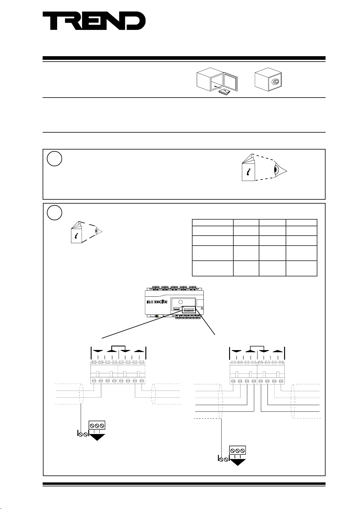
1 Installation - Mounting
Install
1
Install according to IQ3xact or IQ3xcite installation instructions
section 3 steps 1 to 11
Connect IQ System Current Loop Network
2
Network Engineering Manual,
92-1735
2 off 2 part connectors with 4 screw terminals for 0.5 to
2.5 mm2 cross section area (14 to 20 AWG) cable
polarity independent
4 5 6
1 2 3
+ 0
3 Insertion/Replacement of battery 3
4 Disposal 4
IQ3xact Installation Instructions TG200766
IQ3xcite Installation Instructions TG200626
elbaCduab6k9duab2k91seriWfo.oN
2819nedleB
7029nedleB
dnerT
002/FH/22/1/1/PT
)1678nedleB(
dnerT
002/FH/22/2/2/PT
)3278nedleB(
+ 0
m0001
)sdy0901(
m0001
)sdy0901(
m007
)sdy567(
m005
5(
)sdy54
m007
)sdy567(
m005
)sdy545(
m053
)sdy083(
m052
)sdy072(
2
2
2
4
RX
TX
OK
P 0
24V
24V
0V
Using 2 wire method
T- T+ R- R+
1234
earth (ground) screen to
convenient input channel
screen terminal
IQ LAN
T- T+ R- R+
1234
INOUT
Using 4 wire method
T- T+ R- R+
1234
IQ LAN
T- T+ R- R+
1234
INOUT
earth (ground) screen to convenient
input channel screen terminal
IQ3../.../LAN/... Installation Instructions TG200916 Issue 1/D 03/09/07
1
Page 2

IQ3../.../LAN/... Installation Instructions
4 5 64 5 6
2
7 8 97 8 9
3
10 11 12
4
13 14 15
5
16 17 18
6
19 20 21
7
22 23 24
8
25 26 27
9
28 29 30
10
+ 0
+ 0
+ 0
+ 0
+ 0+ 0
+ 0
+ 0
+ 0
+ 0
1 2 31 2 3
1
+ 0
0V
24V
24V
34 35 36
12
37 38 39
13
40 41 42
14
A
31 32 33
P
11
43 44 45
15
46 47 48
16
100-240V
OK RXOK RX
P 0
P 0
P 0
P 0P 0
P 0P 0
P 0
TX
RX
OK
1 Installation - Mounting (continued)
Continue Installation
3
Install according to IQ3xact installation instructions from section 4 step 1 to section
4 step 19, or IQ3xcite installation instructions from section 3 step 13 to section 4
step 20.
IQ3xact Installation Instructions TG200766
IQ3xcite Installation Instructions TG200626
2 Installation - Configuration
Continue Installation
1
Complete section 1 above and IQ3xact installation instructions up to section
4 step 19, or IQ3xcite Installation Instructions up to section 4 step 20.
IQ3xact Installation Instructions TG200766
IQ3xcite Installation Instructions TG200626
Set current loop Network Baud Rate and Address
2
a, Set address switch
0
1
1 2 4 8 16 32 64
e.g. Address = 2 + 16 = 18
address
b, Set baud rate switch
e.g. Baud Rate = 19k2
1, 4 to 9, 11 to 119
0, 2, 3,10 or >119
0
1
9K6
19K2
19k2
9k6
SET
NOT SET
Address = A
=A*
IQ3../.../LAN/...
=A/
=A/
=A/
*Note that the IQ3../.../LAN/... may also use addresses for
its virtual CNC, and for its local supervisor CNC which
should also be unique on the Lan.
IQ system Lan baud rate = B
= B
= B
= B
= B
2
IQ3../.../LAN/... Installation Instructions TG200916 Issue 1/D 03/09/07
Page 3
Installation Instructions IQ3../.../LAN/...
4 5 6
2
7 8 9
3
10 11 12
4
13 14 15
5
16 17 18
6
19 20 21
7
22 23 24
8
25 26 27
9
28 29 30
10
+ 0
+ 0
+ 0
+ 0
+ 0
+ 0
+ 0
+ 0
+ 0
1 2 3
1
+ 0
34 35 36
12
37 38 39
13
40 41 42
14
A
31 32 33
P
11
43 44 45
15
46 47 48
16
100-240V
OK RX
P 0
P 0
P 0
P 0
P 0
P 0
IQ3../.../LAN/...
1 2 3 4
IQ LAN
T- T+ R- R+
1 2 3 4
T- T+ R- R+
1 2 3 4
IQ LAN
T- T+ R- R+
1 2 3 4
T- T+ R- R+
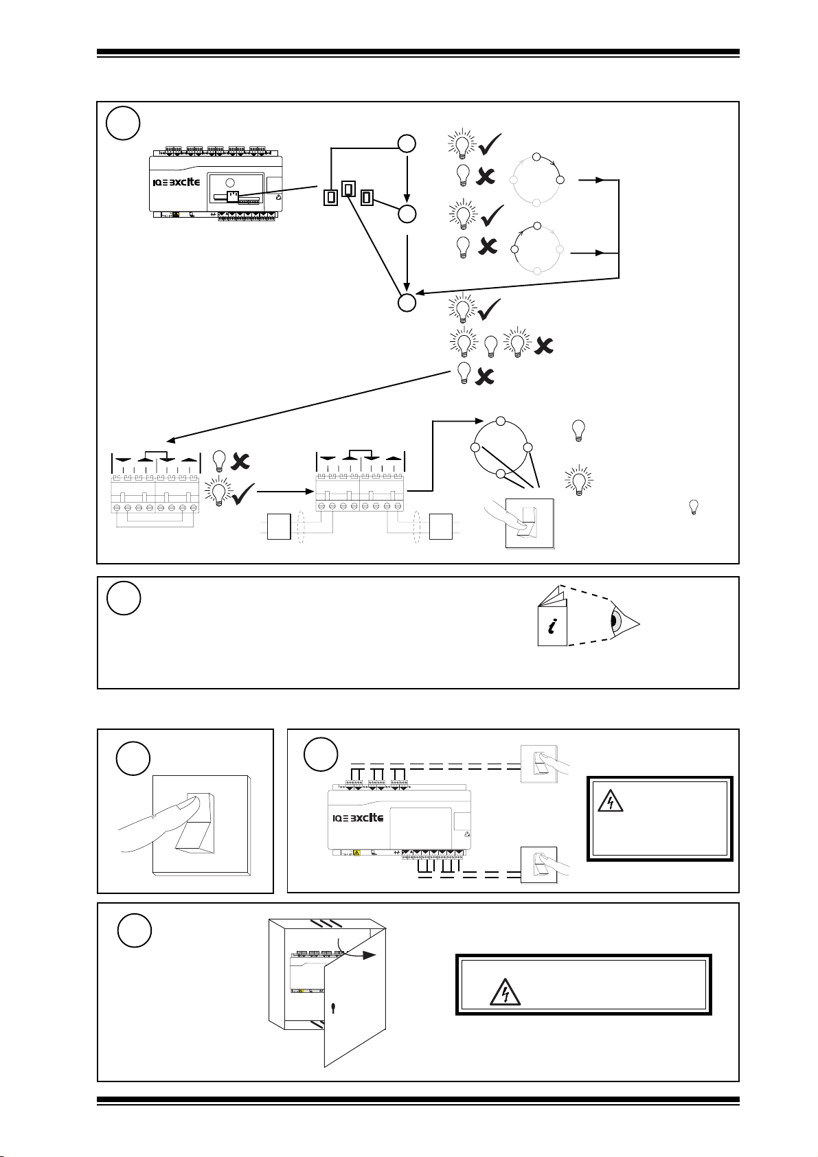
2 Installation - Configuration (continued)
Check network
3
1 2 3
13 14 15
10 11 12
7 8 9
25 26 27
a TX
IQ3../.../LAN/...
IQ LAN
T- T+ R- R+
1234
T- T+ R- R+
1234
RX
RX
TX
OK
P 0
OK RX
37 38 39
24V
24V
0V
TX
OK
b RX
?
IQ3../.../LAN/...
?
c OK
Network Address
0,2,3 or >119
OK
Check network cabling for
OK
IQ Faulty
IQ LAN
T- T+ R- R+
1234
T- T+ R- R+
1234
O
I
short circuits with a
multimeter (NOT Megger)
Check baud rate. Switch on
other nodes until faulty
node is found (OK ).
Correct fault.
Continue Installation
4
Continue installation according to IQ3xact installation
instructions section 4 step 21 on, or IQ3xcite installation
instructions section 4 step 22 on
IQ3xact Installation Instructions TG200766
IQ3xcite Installation Instructions TG200626
3 Insertion/Replacement of Battery (if battery required)
1
Open Panel
3
Switch Off
O
I
4 5 6
1 2 3
1
2
+ 0
+ 0
100-240 V
2
13 14 15
10 11 12
7 8 9
3
5
4
+ 0
+ 0
+ 0
OK RX
Isolate I/O
4 5 6
1 2 3
1
+ 0
+ 0
100-240 V
16 17 18
19 20 21
25 26 27
22 23 24
28 29 30
6
8
9
10
7
+ 0
+ 0 + 0+ 0
+ 0
A
13
11
12
14A
P 0
P 0
P 0
P 0
P 0
P 0
34 35 36
31 32 33
37 38 39
43 44 451546 47 48
40 41 42
P
24 V
24 V
0 V
16 17 18
13 14 15
10 11 12
7 8 9
3
5
2
6
4
+ 0
+ 0
+ 0
+ 0
16
15
13
11
12
14A
P 0
P 0
P 0
P 0
P 0
OK RX
31 32 33
P
24 V
24 V
0 V
P 0
34 35 36
37 38 39
43 44 45
46 47 48
40 41 42
WARNING: Opening the panel may expose
16
O
I
O
I
dangerous voltages.
417-IEC-5036
WARNING: The
connecting leads
may be connected
to supplies. Isolate before
touching.
IQ3../.../LAN/... Installation Instructions TG200916 Issue 1/D 03/09/07
3
Page 4

IQ3../.../LAN/... Installation Instructions
3 Insertion/Replacement of Battery (continued)
Remove Auxiliary Board Cover
4
Remove battery
5
(if replacing battery)
a
b
c
Insert new battery
6
CR 2032
CR2032 3 V
d
Replace Auxiliary Board Cover
7
ab
CR 2032
Warning: The lithium battery must not be
+
recharged, disassembled, burnt or
short circuited. Misuse may cause
explosion or fire. Dispose of carefully
(see section 4, Disposal, below).
Refer to Health and Safety Executive Guidance
Note GS43.
Close Panel
8
4 5 6
16 17 18
13 14 15
19 20 21
1 2 3
22 23 24
25 26 27
10 11 12
7 8 9
28 29 30
3
5
6
8
9
10
1
2
4
7
+ 0
+ 0
+ 0 + 0+ 0
+ 0
+ 0
+ 0
+ 0
+ 0
A
100-240 V
16
13
11
12
14A
P 0
P 0
P 0
P 0
P 0
P 0
OK RX
34 35 36
37 38 39
31 32 33
43 44 451546 47 48
40 41 42
P
24 V
24 V
0 V
Reconnect Supply to I/O
9
4 5 6
1 2 3
1
2
+ 0
+ 0
16 17 18
13 14 15
10 11 12
7 8 9
3
5
6
4
+ 0
+ 0
+ 0
+ 0
Switch On
10
O
I
O
I
IQ3.../.../XNC/.../USA/UL/24 is
UL rated as ‘UL916 listed open
energy management
100-240 V
11
P 0
OK RX
31 32 33
P
24 V
24 V
0 V
16
15
13
12
14A
P 0
P 0
P 0
P 0
P 0
34 35 36
37 38 39
43 44 45
46 47 48
40 41 42
O
I
equipment’.
4 Disposal
WEEE Directive :
At the end of their useful life the packaging,
product, and any battery should be disposed
Do not dispose of with normal household waste.
Do not burn.
Manufactured for and on behalf of the Environmental and Combustion Controls Division of Honeywell Technologies Sàrl, Ecublens, Route
du Bois 37,Switzerland by its Authorized Representative, Trend Control Systems Limited.
of by a suitable recycling centre.
Trend Control Systems Limited reserves the right to revise this publication from time to time and make changes to the content
hereof without obligation to notify any person of such revisions or changes.
Trend Control Systems Limited
P.O. Box 34, Horsham, West Sussex, RH12 2YF, UK. Tel:+44 (0)1403 211888 Fax:+44 (0)1403 241608 www.trend-controls.com
Trend Control Systems USA
6670 185th Avenue NE, Redmond, Washington 98052, USA. Tel: (425)897-3900, Fax: (425)869-8445 www.trend-controls.com
4
IQ3../.../LAN/... Installation Instructions TG200916 Issue 1/D 03/09/07
 Loading...