

Page 1
Important: Retain these instructions
J 1 2 M N C
J 1 3
Installation Instructions
KIT/NODE/IQ25x
Node Mounting Kit
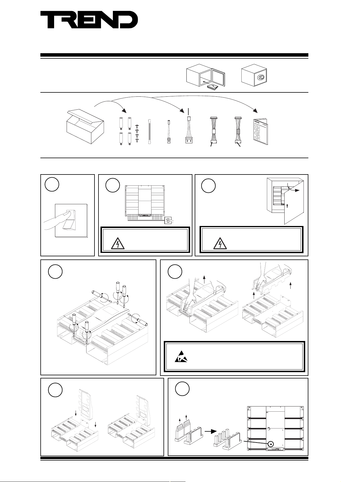
1 UNPACKING
EJ104091
EARTH
(GROUND)
CABLE/EJ102364
POWER
78-2781
NETWORK
CABLE/EJ103817
RS232/TMNE
25 W Male
sheath
25 W
Female
red
black
sheath
MolexMolex
CABLE/EJ100179A001
RS232/CNC2, PNC2
2 INSTALLING A NODE IN IQ250/251 USING KIT/NODE/IQ25X
Switch Off
1
O
I
WARNING: The connecting leads may
2
Isolate I/O
be connected to input power.
Isolate before touching.
Open Panel
3
IQ251/USA
The unit is UL rated as
'UL916, listed open energy
management equipment'
WARNING: Opening the panel may expose
dangerous voltages.
KIT/NODE/IQ25x
Installation
Instructions,
TG200595
417-IEC-5036
2
5
Q
1
I
Unscrew Main Cover
4
Remove 6 screws
Store Cover on Back of Unit
6
Unscrew Main Cover
5
CAUTION: This unit contains static sensitive devices. Suitable anti-static
Pull off links
precautions should be taken throughout this operation to
prevent damage to the unit. BS EN100115/1 Basic
Specification: protection of electrostatic sensitive devices.
Remove Network Links
Not ANC, AND, MNC, TMN if on internetwork.
7
Not INC2 if used as internetwork repeater
(dumb/normal = normal, address>=100)
KIT/NODE/IQ25x Installation Instructions TG200595 Issue 1/B 21/1 1/06
J 1 3
J 1 2 M N C
ON
ADD RES S
1
Page 2
KIT/NODE/IQ25x Installation Instructions
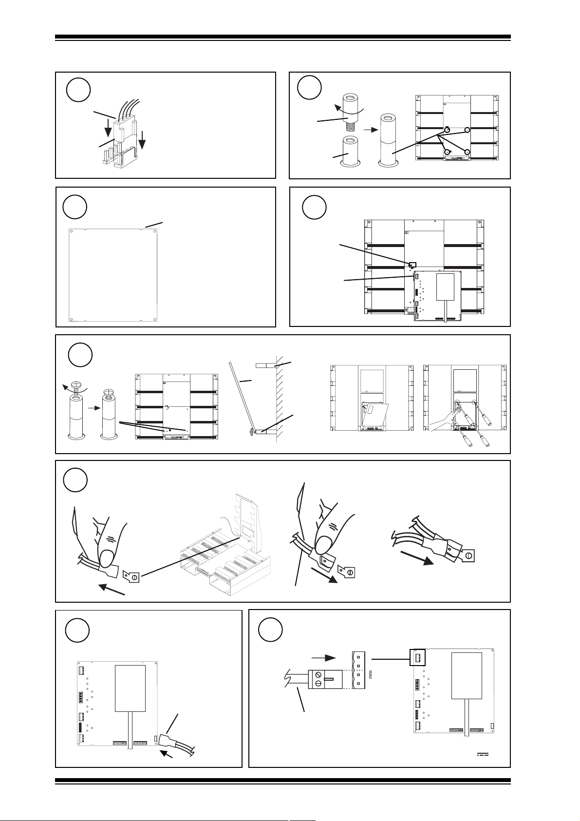
2 INSTALLING A NODE IN IQ250/251 USING KIT/NODE/IQ25X (Continued)
Connect Local Network Cable
8
Cable
78-2781
supplied
Polarised
connector
J 1 3
J 1 2 M N C
Not ANC, AND, MNC, TMN if on
internetwork.
Not INC2 if used as internetwork
repeater (dumb/normal =
normal, address >= 100).
Check Node Card
Node card must have semi-circular cutouts
10
Semi-circular cutouts
e.g. CNC+, ANC+, PNC+,
INC+, MNC, AND, XN28,
XNC, and appropriate latest
nodes (TMNH, TMNE,
CNC2, PNC2, INC2,
LINC/FTT).
Note that MNC has only 2
semi-circular cutouts so will
be a tight fit.
Fit board to inserts
12
(a) Fit lower screws
9
Nylon
insert
Aluminium
insert
11
IQ251 node
output power
Adjacent to
board input
power connector
(b) Slide board onto lower screws
aluminium
threaded
node
board
insert
Install Nylon Inserts
4 off
ON
ADDR ESS
Orientate board
Ensure input power connectors adjacent
J9J8
La n B La n A
ON
ADD RE SS
(c) Push board into
position
J7
(d) Tighten screws
J1 6
J1 5
M od e m
De v A
De v B
ET 1
13
14
ON
ADDR ESS
Connect Earth (ground) Cable
(a) Remove earth (ground) cable if
one already fitted to tag (e.g. for
NDP)
Connect Earth (ground) to
Node Board
Cable EJ104091
J 9J 8
L a n B L a n A
J 7
J 1 5
M o de m
D e v A
D e v B
supplied
E T 1
J 1 6
lower
nylon
insert
(b) Push on receptacle
(c) Replace existing earth (ground)
connection if one previously fitted
(e.g. for NDP)
Cable EJ104091 supplied
Connect Input Power Cable to Node Board
15
J2
~
~
0 V
J 9J 8
L a n B L a n A
Cable EJ102346 supplied
J 7
J 1 5
D e v A
E T 1
J 1 6
M o de m
D e v B
Ensure socket is connected to correct terminal pins (+, -, or , 0V)
2
KIT/NODE/IQ25x Installation Instructions TG200595 Issue 1/B 21/11/06
Page 3
Installation Instructions KIT/NODE/IQ25x
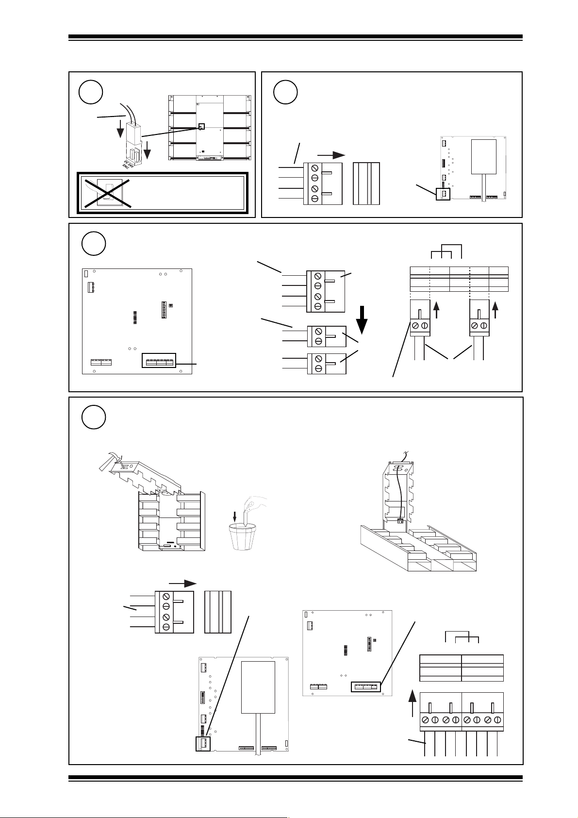
2 INSTALLING A NODE IN IQ250/251 USING KIT/NODE/IQ25X (Continued)
16
Cable
EJ102364
supplied
Polarised
18
J 1
P O W E R
J 1 5
J 1 1
Connect Input Power Cable to
IQ25x
17
Connect Local Network to Node Board (4 wide)
Not ANC, AND, MNC, TMN if on internetwork
Not INC2 if used as internetwork repeater (dumb/normal =
normal, address >=100). For LINC see step 18
Cable 78-2781 supplied
ON
ADDR ESS
O
DO NOT SWITCH ON
1
Connect Local Network to Node Board (8 wide)
For LINC only (if not used as internetwork Lan extension node (address <100))
Cable 78-2781
supplied
1 0
9
Cable 78-2781
L A N
J 9 J 1 7
J 1 2
modified
Local network
(a) Rewire cable cable 78-2781
T-
T+
R-
Remove
4 way
plug
R+
TT+
RR+
Wire
2 x 2
way
plugs
Ensure sockets are connected to correct terminal pins
T T +
Lan A
R R +
(b) Connect cable
T - R - R +T + T - R - R +T +
Cable 78-2781 modified
J 9J 8
L a n B L a n A
J 7
D e v A
E T 1
J 1 5
J 1 6
M o d e m
D e v B
S C N
S C N
Connect Internetwork and Internetwork Segment A to Node Board
19
For ANC, AND, XN28, MNC, or LINC on internetwork (for LINC connection see 19d)
For INC2 if used as internetwork repeater (dumb/normal = normal, address >=100)
(a)
(c) Connect 4 wide
Internetwork
cable
T T +
R R +
Lan A
(b)
(d) Connect 8 wide
LINC
J 1
P O W E R
L A N
J 9 J1 7
J 1 5
J 1 1
J 1 2
Internetwork
10
9
R -
T +
T -
R +
R -
T +
R +
T -
J 9J 8
L a n B L an A
(Lan A)
Internetwork Segment A (INC2)
Internetwork (TMN)
J 7
J 1 5
D e v A
E T 1
J 1 6
M od em
D e v B
KIT/NODE/IQ25x Installation Instructions TG200595 Issue 1/B 21/11/06
Internetwork cable
3
Page 4

KIT/NODE/IQ25x Installation Instructions
J 7
E T 1
J 1 6
D e v B
J 1 5
D e v A
J 9
J 8
L a n B L an A
M o de m
J 7
E T 1
J 1 6
D e v B
J 1 5
D e v A
J 9
J 8
L a n B L a n A
M od em
J 7
E T 1
J 1 6
D e v B
J 1 5
D e v A
J 9J 8
L a n B L a n A
M od em
2 INSTALLING A NODE IN IQ250/251 USING KIT/NODE/IQ25X (Continued)
Connect Internetwork and Internetwork Segment B to Node Board
20
Internetwork for INC, INC2
Internetwork Segment B for INC2 if used as internetwork repeater (dumb/normal = normal, address >=100)
(a)
(c) Connect internetwork
Internetwork
cable
Connect RS232 to Node Board
21
For CNC, PNC, ANC, XNC+, XN28, AND, CNC2, PNC2, TMNE
(a)
(b)
either pierce grommet
or use copex gland
T T +
Lan B
R R +
(Lan B)
Internetwork
Internetwork Segment B if
INC2 used as
internetwork repeater
(b)
CNC2, PNC2
RS232 (Dev B Modem)
black sheath
CABLE/EJ100179A001
supplied
25 Way D type
female
1
4
10 Way Molex Socket
(pins 2 linked to 4, 3
linked to 5)
polarised
TMNE
RS232 (Dev B Modem)
red sheath
CABLE/EJ103817
supplied
10 Way Molex Socket
25 Way D type
male
1
polarised
KIT/NODE/IQ25x Installation Instructions TG200595 Issue 1/B 21/11/06
Page 5

Installation Instructions KIT/NODE/IQ25x
J 7
E T 1
J 1 6
D e v B
J 1 5
D e v A
J 9
J 8
L a n B L an A
M o de m
2 INSTALLING A NODE IN IQ250/251 USING KIT/NODE/IQ25X (Continued)
Connect Device to IQ25x RS232/Modem Connector
22
CNC2
9 Way D type Female
CABLE/58-0750
25 Way D type Male
PNC2
25 Way D type Male
Special cable, pins 3,7,20
connected straight through
25 Way D type Male
TMNE
Modem/
Terminal
Adaptor
25 Way D type Male
Standard 24 way cable
wired 1 to 1 through to
25 to 25
25 Way D type Female
Route Special Device Cables
23
For ENC, MNC, TMNH
(a) Remove TMNH adaptor plug
For TMNH only
(c) Knock out hole
(e) Replace TMNH adaptor plug
For TMNH only
(b) Identify cable
e.g. TMNH
(d) Route cable through hole
(f) Connect to device
MNC, TMNH
PSTN
Integral modem
(TMNH only)
either pierce grommet
or use copex gland
KIT/NODE/IQ25x Installation Instructions TG200595 Issue 1/B 21/11/06
5
Page 6

KIT/NODE/IQ25x Installation Instructions
T -
T +
R -
R +
T -
T +
R -
R +
N E T W O R K
O U T
I N
2 INSTALLING A NODE IN IQ250/251 USING KIT/NODE/IQ25X (Continued)
Link Network Connectors
24
Connect to LonWorks
25
For LINC only
(a) Knock out hole
If ANC, AND, XN28, MNC, TMN, is fitted and IQ25x is not networked (stand alone)
R XT X
O N
A D D R E S S
(b) Route cables through hole
either pierce grommet
or use copex gland
(c) Connect Lon cables
J 1
P O W E R
10
9
L A N
J 9 J1 7
J 1 2
Node
Controller
Data Sheet
Check Settings
26
J 1 5
J 1 1
If appropriate
(a) Check network baud rate.
(b) Check network address and dumb/normal switch.
(c ) Check 2nd network/device baud rate.
Check Node Controller
28
TMN type board shown
Check node data sheet for
location of LEDs on other
boards
J 9J 8
L a n B L a n A
J 7
D e v A
Switch On
27
O
1
a PWR ON
(green)
b W/DOG
(red)
E T 1
J 1 6
J 1 5
M od em
D e v B
Check input
power
Node Faulty
6
KIT/NODE/IQ25x Installation Instructions TG200595 Issue 1/B 21/11/06
Page 7

Installation Instructions KIT/NODE/IQ25x
I Q 2 3 x
?
2 INSTALLING A NODE IN IQ250/251 USING KIT/NODE/IQ25X (Continued)
Check Trend Lan and Internetwork sections
29
Do separate check for each Lan/Internetwork segment
TMN type board
shown
Check node data
sheet for location
of LEDs on other
boards
J 9J 8
L a n B L a n A
aRX
(yellow)
bTX
(yellow)
I Q 2 3 x
?
O U T
T -
T +
30
LAN
N E T W O R K
I N
OK
T -
R +
R -
R -
R +
T +
Lift Cover from
Back of Unit
J 7
Node Faulty
J 1 5
D e v A
T X - T X + R X - R X +
M od em
D e v B
LAN
E T 1
J 1 6
c OK
(green)
Network Address Invalid
0, 2, 3 or >119
OK
Check baud rate . Check
network cabling for short circuits
with a multimeter (NOT Megger)
Power up other nodes until
31
O
I
Replace Cover
faulty node is found
(OK ). Correct fault.
32
Screw on Main Cover
33
IQ251/USA
Close Panel
2
5
Q
1
I
The unit is UL rated as
'UL916, listed open energy
management equipment'
KIT/NODE/IQ25x Installation Instructions TG200595 Issue 1/B 21/11/06
7
Page 8

KIT/NODE/IQ25x Installation Instructions
2 INSTALLING A NODE IN IQ250/251 USING KIT/NODE/IQ25X (Continued)
Reconnect Input Power to I/O
34
Test System
36
3 DISPOSAL
O
I
Node Installation Instructions
Configure
35
If required
(INC, INC2, ANC, AND, XN28, MNC, TMN, ENC,
XNC+, LINC)
Node Installation Instructions
WEEE Directive :
At the end of their useful life the packaging ,
product, and batteries should be disposed of
Do not dispose of with normal household waste.
Do not burn.
by a suitable recycling centre.
Manufactured for and on behalf of the Environmental and Combustion Controls Division of Honeywell Technologies Sàrl, Ecublens, Route
du Bois 37,Switzerland by its Authorized Representative, Trend Control Systems Limited.
Trend Control Systems Limited reserves the right to revise this publication from time to time and make changes to the content
hereof without obligation to notify any person of such revisions or changes.
Trend Control Systems Limited
P.O. Box 34, Horsham, West Sussex, RH12 2YF, UK. Tel:+44 (0)1403 211888 Fax:+44 (0)1403 241608 www.trend-controls.com
Trend Control Systems USA
6670 185th Avenue NE, Redmond, Washington 98052, USA. Tel: (425)897-3900, Fax: (425)869-8445 www.trend-controls.com
8
KIT/NODE/IQ25x Installation Instructions TG200595 Issue 1/B 21/11/06
 Loading...