

Page 1
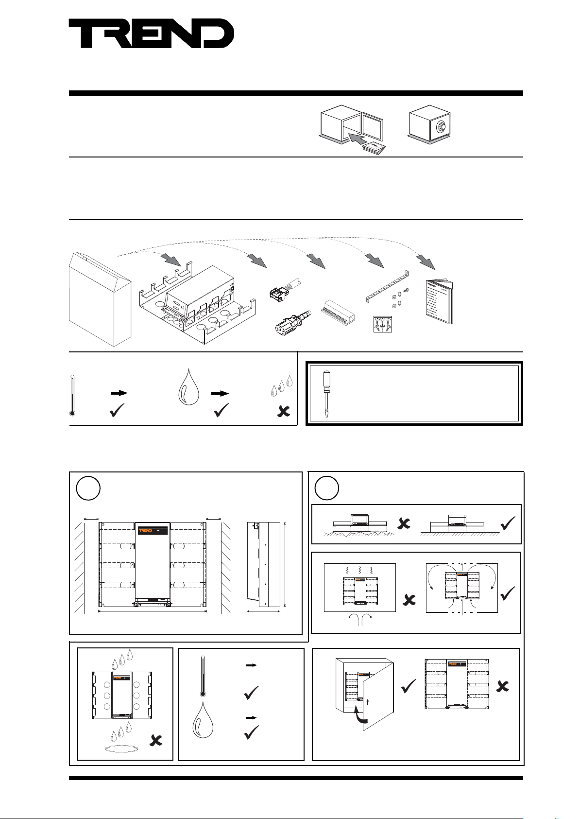
Important: Retain these instructions
IQ251
Installation Instructions
IQ251
Controller
Contents
1 Unpacking ............................................. 1
2 Storing .................................................. 1
3 Installation ............................................. 1
1 Unpacking
2 Storing
(14 °F)
+50 °C
(122 °F)
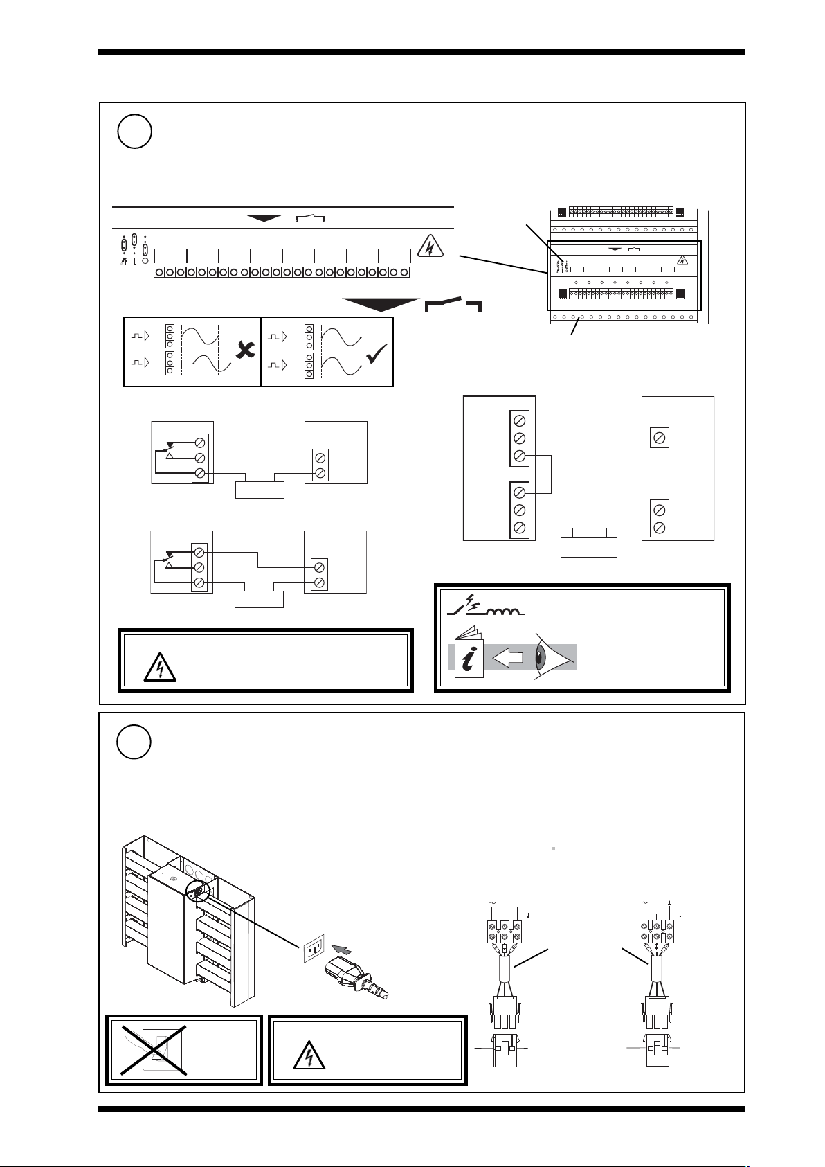
HO
2
0-10 °C
3 Installation
3.1 Installation - Mounting ....................... 1
3.2 Installation - Configuration ................ 7
4 Mounting in an Enclosure, ENCLS/.. ....... 12
5 Connecting to PC using Supervisor Port 12
6 Replacing the Battery ........................ 13
/24VAC,
90 %RH
/24VDC only
/230 only
/EIN/, /EAO/,
or /EDO/
(option)
PART/LA102359K
(option)
It is recommended that the installation should
comply with the HSE Memorandum of Guidance
on Electricity at Work Regulations 1989.
For USA install equipment in accordance with
the National Electric Code.
7 Zero Address/Baud Rate Switch Reset 15
8 Replacing the Fuse ............................... 16
9 Disposal ............................................... 16
IQ251 Installation
Instructions,
TG103483
3.1 Installation - Mounting
Dimensions
1
30 mm (2")
IQ251
30 mm (2")
a
b
440 mm (17.32")
550 mm (21.7")
c
IQ251
d
HO
2
0 °C
(32 °F)
0 %RH
175 mm (6.9")
+45 °C
(113 °F)
90 %RH
Requirements
2
IQ251
e
IQ251/USA: This unit is UL rated as 'UL916, listed open
energy management equipment'.
IQ251
IQ251
IQ251 Installation Instructions TG103483 Issue 3, 8/10/08
1
Page 2
IQ251 Installation Instructions
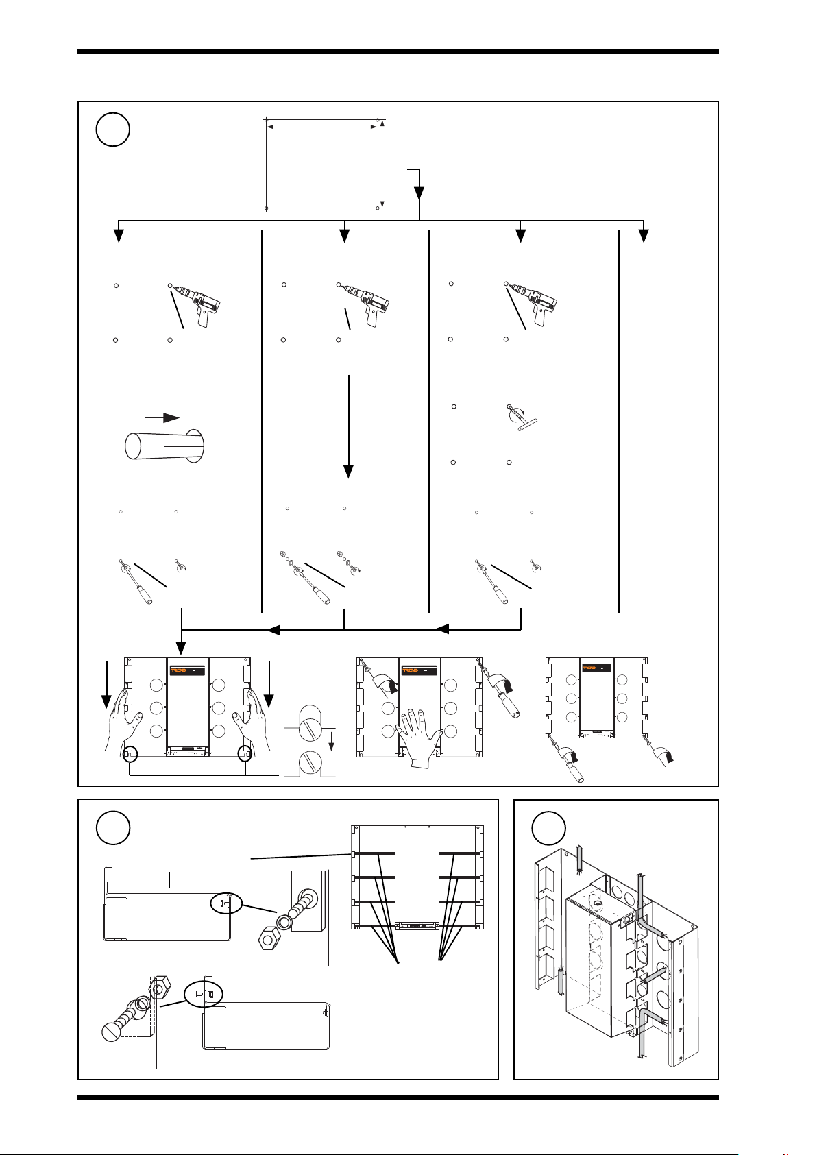
3.1 Installation - Mounting (continued)
510 mm (20.08")
Mounting
3
If mounting on:
Wall
a
4 holes
Ø 8 mm (0.31")
b Insert rawl plugs b Tap holes
c Insert lower screws
No 12 wood screws
Metal Panel rear access Metal Panel no rear access ENCLS
a
4 holes
Ø 8 mm (0.31")
b -
c Insert lower screws
M6 screws and nuts
415 mm (16.34")
a
c Insert lower screws
see section 5
4 holes
Ø 8 mm (0.31")
Tap 4 M6 holes
M6 screws
d
Fit earthing (grounding) bars
If PART/LA102359K available
4
a
earthing (grounding) bar
b
IQ251
e
IQ251
f
IQ251
Route Cables
5
positions of earthing
(grounding) bars
2
IQ251 Installation Instructions TG103483 Issue 3, 8/10/08
Page 3
Installation Instructions IQ251
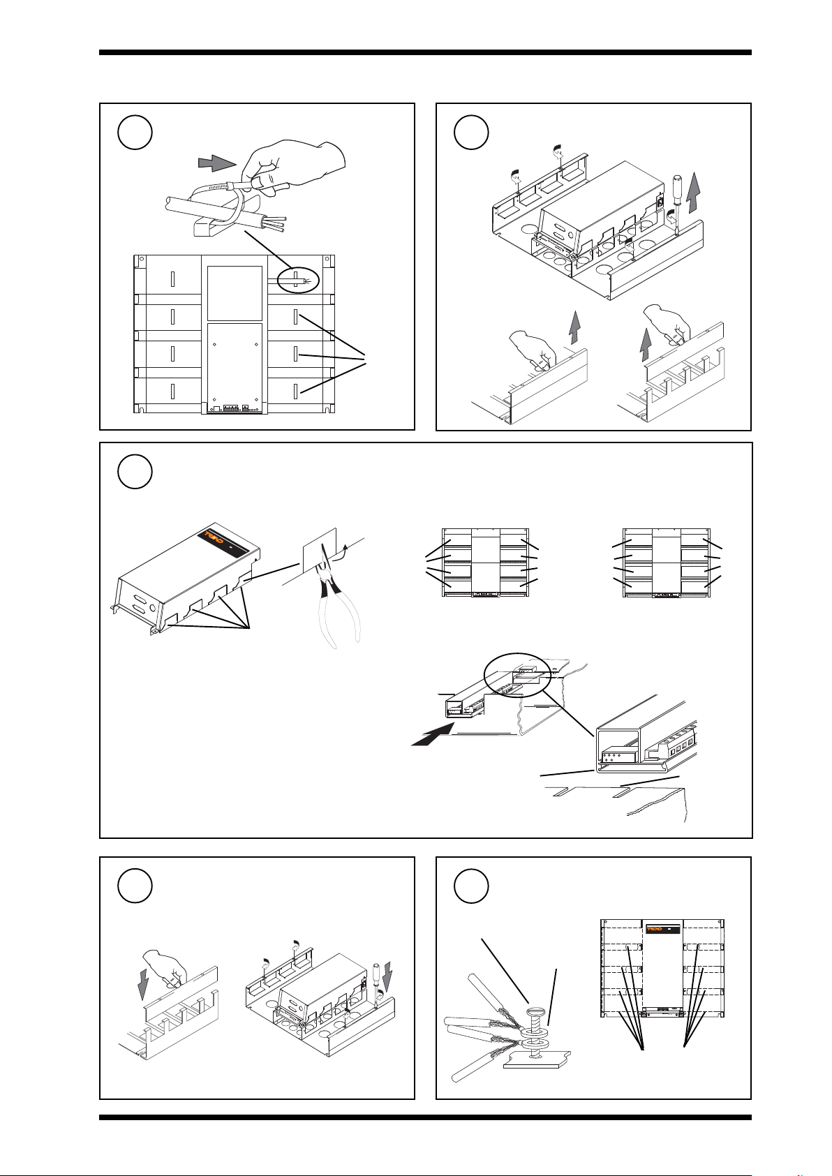
3.1 Installation - Mounting (continued)
Tie Cables
6
Fit I/O Modules
8
a Snap off section if required
IQ251
Remove side plates
7
a
b
cable
cleats
c
c Locate positions
IQ251< v1.2 IQ251 (v1.2 or greater)
EIN
EIN
only
EAO
or
EDO
or
EAO
or EDO
EIN
or
EAO
or
EDO
snap off
sections
b Select Modules
/EIN/ 8 A na log + 8 Digital i nput channels
/EAO/ 8 Analog output channels
/EDO/ 8 Digital (relay) output channels
Replace Side Plates
9
ab
d Slide into position
Terminate Screens
10
M4 (supplied)
If earthing (grounding) bar fitted
slot
2 eyelets
maximum
tongue
IQ251
IQ251 Installation Instructions TG103483 Issue 3, 8/10/08
earthing (grounding) bars
3
Page 4
IQ251 Installation Instructions
S
3.1 Installation - Mounting (continued)
11
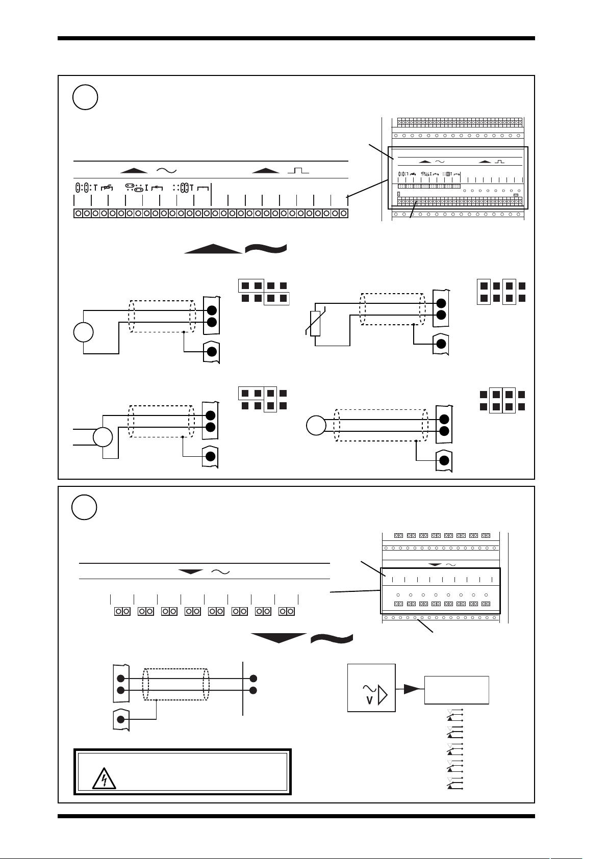
Connect Inputs
IQ system TP/1/1/22/HF/200 (Belden 8761) cable recommended for all inputs
Cable size 0.5 to 2.5 mm2 (20 to 14 AWG) - Cu only
8 8
A I 1
A I 2
A I 3
A I 4
A I 5
A I 6
I N C
I N C
I N C
I N C
I N C
I N C
I N C
A I 7
Analogue Input (AI1 to AI8)
Current Input (loop powered)
I (0 to 20 mA)
SIG
S
24 V
Current Input (externally powered)
I (0 to 20 mA)
SIG
S
0 V
A I 8
D I 1
I N C
I N C
IN
C (24 V)
Earthing
(grounding) bar
IN
C (0
V)
Earthing
(grounding) bar
I N C
D I 2
AIn
AIn
I N C
/EIN/ module
8 8
A I 1
A I 2
A I 3
A I 4
A I 5
A I 6
A I 7
A I 8
D I 1
D I 2
D I 3
D I 4
D I 5
D I 6
D I 7
IN C
IN C
IN C
IN C
IN C
IN C
IN C
IN C
IN C
IN C
IN C
IN C
D I 3
D I 4
D I 5
D I 6
D I 7
I N C
I N C
I N C
I N C
I N C
D I 8
D I 8
IN C
IN C
IN C
IN C
earthing (grounding) bar (option)
IL
Thermistor Input
T
IN
AIn
C
Earthing
(grounding) bar
IX
Voltage Input
V
V (0 to 10 V)
+
IN
AIn
C (0 V)
0 V
Earthing
(grounding) bar
Connect Analogue Outputs
12
IQ system TP/1/1/22/HF/200 (Belden 8761) cable recommended for all analogue outputs
if /EAO/ fitted
Cable size 0.5 to 2.5 mm2 (20 to 14 AWG) - Cu only
/EAO/ module
8
A O 2
A O 1
O U T
C
O U T C
O U T C
A O 3
A O 4
A O 5
A O 6
A O 7
O U T C
O U T C
O U T C
O U T C
O U T C
A O 8
Analogue Output Channels (AO1 to AO8)
0 to 10 V (max), 20 mA (max)
AOn
OUT
+
C
0
LOAD
I Q 2 5 x
Earthing
(grounding) bar
WARNING: The wires may be connected to
hazardous voltages. Disconnect power
before attempting any wiring.
8
A O 1
A O 2
A O 3
A O 4
A O 5
A O 6
A O 7
O U T
C
O U T C
O U T C
O U T C
O U T C
A O 8
O U T C
O U T C
O U T C
earthing (grounding) bar (option)
R e l a y
M o d u l e
S R M V =
2 S R M =
2 R M =
3 R M = x 3
n R M
x 1
x 2
x 2
(RLM/HLM)
(HCM/TCM)
6 R M = x 6
4
IQ251 Installation Instructions TG103483 Issue 3, 8/10/08
Page 5
Installation Instructions IQ251
EJ105383
24V
Earth
3.1 Installation - Mounting (continued)
Connect Digital Outputs
13
If /EDO/ fitted
Cable size 0.5 to 2.5 mm2 (20 to 14 AWG) - Cu only
8
D O 2 D O 3 D O 4 D O 5 D O 6 D O 7 D O 8D O 1
C N o N c C N o N c C N o N c C N o N c C N o N c C N o N c C N o N c C N o N c
Digital Output Channels (DO1 to DO8)
n+1
Æ
a
n
Æ
b
n+1
Æ
a
n
Æ
a
Drive on, load on
n
IQ
NC
NO
C
LOAD
Power
Drive off, load on
n
IQ
NC
NO
C
LOAD
24 Vdc (inductive) 2 A
240 Vac single phase throughout 7 A (resistive) 5 A (inductive, Cosø > = 0.4)
30 Vdc at 5 A (resistive)
For IQ251/USA, UL rating applies up to 30 V
/EDO/ module
C A U T IO N
H IG H V O L T A G E
M A Y B E P R E S E N T
IS O L A T E E L S E W H E R E
C N o N c C N o N c C N o N c C N o N c C N o N c C N o N c C N o N c C N o N c
8
D O 2 D O 3 D O 4 D O 5 D O 6 D O 7 D O 8D O 1
earthing (grounding) bar (option)
2 outputs - raise/lower
n + 1
IQ
NC
NO
Actuator
L
C
n
NC
NO
C
R
C
Power
Power
WARNING: The wires may be connected to
hazardous voltages. Disconnect power
before attempting any wiring.
14
Connect Input Power
A switch or circuit breaker must be included in the input
power to the unit and be in close proximity to it, and must be
clearly marked as the disconnecting device for the unit.
IQ251 Consumption <=100 VA
if /230
230 Vac +15 %, -10 %,
50 to 60 Hz
IEC
Arc suppression
recommended
Relay Output Arc
Suppression Installation
Instructions TG200208
if /24 VAC or /24 VDC
24 Vac +25 %, -10 %, 50 to 60 Hz
24 Vdc + 25%, -10 %, 50 to 60 Hz
If /24VAC
24 Vac: Isolated transformer
winding supply 1 controller
If /24VDC
24 Vdc: May supply several
controllers
only
Earth (ground) recommended
24 Vac 24 Vac
Mat-N-Loc to
terminal adaptor
(supplied)
24 V 0 V
24V
EJ105383
Earth
DO NOT
O
SWITCH
I
ON
IQ251 Installation Instructions TG103483 Issue 3, 8/10/08
WARNING: This apparatus must be
earthed (grounded)
using input power
connector.
5
Page 6

IQ251 Installation Instructions
T R T R T R T R T R T R T R T R
3.1 Installation - Mounting (continued)
15
Connect Network
Terminal size 0.5 to 2.5 mm2 (20 to 14 AWG)
elbaCduab2k1duab6k9duab2k91
2819nedleB
7029nedleB
)1678nedleB(
)3278nedleB(
m0001
)sdy0901(
m0001
)sdy0901(
m0001
002/FH/22/1/1/PTmetsysQI
002/FH/22/2/2/PTmetsysQI
)sdy0901(
m0001
)sdy0901(
2 wire
N E T W O R K
O U T
T -
T +
T -
R -
R +
I N
e a r t h i n g b a r
R +
R -
T +
Network Engineering Manual
92-1735
IQ251
fo.oN
m0001
m0001
m007
m005
m007
)sdy0901(
)sdy0901(
)sdy567(
)sdy545(
)sdy567(
m005
)sdy545(
m053
)sdy083(
m052
)sdy072(
seriW
2
2
2
4
polarity independent
4 wire
R XT X
O U T
N E T W O R K
T -
R -
R +
T +
O N
A D D R E S S
I N
e a r t h i n g b a r
T +
T -
R +
R -
T R T R T R T R
Connect Auxiliary Output Supply
16
Terminal size 0.5 to 2.5 mm2 (20 to 14 AWG)
Auxiliary output supply socket
IQ251
24V
+
-
Imax = 500 mA
24 Vdc 0 V
e.g.
IQ251
24V
AO
+
-
C
2RM
24V
IN
0V
6
IQ251 Installation Instructions TG103483 Issue 3, 8/10/08
Page 7

Installation Instructions IQ251
IQ251
ADDRESS
ON
RX
TX
RX
TX
1
284
1 6
3 2
6 4
1 K 2
9 K 6
1 9 K 2
B A U DA D D R E S S
O N
RX
TX
3.2 Installation - Configuration
Switch Off
1
O
I
Open Panel
3
IQ251/USA
The unit is UL rated as
'UL916, listed open energy
management equipment'
Isolate I/O
2
WARNING: The connecting leads may
be connected to supplies.
Isolate before touching.
4
IQ251
Disconnect I/O
IQ251
IQ251
O
I
WARNING: Opening the panel may expose
5
O N
1
284
Baud Rate = B
dangerous voltages.
417-IEC-5036
Set the Network Baud Rate
1 6
3 2
6 4
9 K 6
1 9 K 2
B A U DA D D R E S S
1 K 2
9 K 6
1 9 K 2
1 K 2
9 K 6
1 9 K 2
1 K 2
9 K 6
1 9 K 2
R XT X
1 K 2
= 19k2 baud
= 9k6 baud
= 1k2 baud
= B
= B
WARNING: The connecting leads may be
connected to supplies. Isolate before
touching.
Set the Network Address
6
IQ251
IQ251
e.g.
R XT X
ON
A DD R E SS
ON
A DD R E SS
Address = 2 + 16 = 18
SET
NOT SET
Address = A
= A
= A
/
IQ251
= A
/
address
= B
1, 4 to 9, 11 to 119
0, 2 ,3 ,10 or >119
= A
/
= B
IQ251 Installation Instructions TG103483 Issue 3, 8/10/08
7
Page 8

IQ251 Installation Instructions
3.2 Installation - Configuration (continued)
Link Analogue Input Channels
7
If /EIN/ fitted and link header not used
8 8
A I1
A I2
A I3
A I4
A I5
A I6
A I7
A I8
D I1
D I2
D I3
D I4
D I5
IN C
IN C
IN C
IN C
IN C
IN C
IN C
IN C
D I6
IN C
IN C
IN C
IN C
IN C
IN C
IN C
A I n - 1 A I n A I n + 1 A I 4
I N C I N C I N C I N C
A I n - 1 A I n A I n + 1 A I 4
Set Digital Output Links
8
if /EDO/ fitted
/EIN/ module
D I7
D I8
IN C
A I 1
A I 2
I N C
I N C
I N C
Current loop
powered
Current
external
powered
8 8
A I 3
A I 4
A I 5
A I 6
A I 7
A I 8
D I 1
D I 2
D I 3
D I 4
D I 5
D I 6
D I 7
I N C
I N C
I N C
I N C
I N C
I N C
IL
IX
I N C
I N C
Thermistor
Voltage
I N C
I N C
I N C
I N C
I N C
D I 8
T
V
8
a identify correct link
D O 2 D O 3 D O 4 D O 5 D O 6 D O 7 D O 8D O 1
C N o N c C N o N c C N o N c C N o N c C No N c C N o N c C N o N c C N o N c
/EDO/ module
Warning: These terminals may
be connected to
hazardous voltages.
b set link appropriately
D O 2 D O 3 D O 4 D O 5 D O 6 D O 7 D O 8D O 1
C N o N c C N o N c C N o N c C N o N c C N o N c C N o N c C N o N c C N o N c
8
J 1 J 2 J 3 J 4
J 5 J 6 J 7 J 8
Normally set to
Auto ( )
O
I
8
IQ251 Installation Instructions TG103483 Issue 3, 8/10/08
Page 9

Installation Instructions IQ251
RX
TX
RX
TX
3.2 Installation - Configuration (continued)
9
Switch On
O
I
Check Controller
10
a PWR
(green)
IQ251
R XT X
O N
A D D R E S S
Check input
power
b WD
(red)
IQ Faulty
c I/O
(red)
IQ Faulty
IQ Faulty
11
Check Network
IQ251
R XT X
O N
A D D R E S S
IQ251
aRX
(yellow)
?
IQ251
bTX
(yellow)
?
c LAN
(green)
Network Address Invalid
N E T W O R K
O U T
T -
R -
T +
I N
T -
R +
R -
R +
LAN
T +
IQ Faulty
N E T W O R K
O U T
I N
IQ251
LAN
Check baud rate . Check
network cabling for short circuits
0, 2, 3 or >119
with a multimeter (NOT Megger)
T -
T -
R -
T +
R +
R -
R +
T +
O
I
Power up other nodes until
faulty node is found
(LAN ). Correct fault.
IQ251 Installation Instructions TG103483 Issue 3, 8/10/08
9
Page 10

IQ251 Installation Instructions
RX
TX
A D D R E S S
O N
8
A O 1
O U T
C
A O 2
O U T C
A O 3
O U T C
A O 4
O U T C
A O 5
O U T C
A O 6
O U T C
A O 7
O U T C
A O 8
O U T C
S
3.2 Installation - Configuration (continued)
Configure
12
IQ Configuration Manual 90-1533
IQ251 Data Sheet TA102315
SET Manual TE200147
X.IQ2
IQ251
Also set time, day, date
Test Inputs
13
if /EIN/ fitted
SET
a
Switch off
IQ251
IQ251
OR
9 Way 'D type'
Female
CABLE/EJ101442
SUPERVISOR
RJ11
b
O
I
14
Switch off
a
Switch on
cd
O
I
Test Analogue Outputs
if /EAO/ fitted
b
O
I
/EAO/
Switch on
/EIN/
IQ251
S
A I 1
A I 2
IQ251
A I 3
IN C
IN C
IN C
(yellow)
dc
O
I
ΔT = X
8 8
A I 4
A I 5
A I 6
A I 7
A I 8
IN C
IN C
IN C
IN C
IN C
IN C
IQ251
D I 1
IN C
D I 2
D I 3
D I 4
IN C
IN C
(yellow)
D I 5
D I 6
D I 7
IN C
IN C
IN C
e.g. VB
D I 8
IN C
10
IQ251 Installation Instructions TG103483 Issue 3, 8/10/08
Page 11

Installation Instructions IQ251
8
D O 2 D O 3 D O 4 D O 5 D O 6 D O 7 D O 8D O 1
C N o N c C N o N c C N o N c C N o N c C N o N c C N o N c C N o N c C N o N c
RX
TX
A D D R E S S
O N
3.2 Installation - Configuration (continued)
Test Digital Outputs
15
if /EDO/ fitted
Switch off
a
16
O
I
Backup
b
Switch on
c
Set digital output links (see step 8) to
d
check HVAC equipment wiring if
required
O
I
/EDO/
IQ251
N C
N O
C
Equipment
I
e.g.
I
N C
IQ251
N O
C
Equipment
e.g.
O
O
Check auto action
e
IQ251
N C
N O
C
(yellow)
SET Manual TE200147
SET
(compare)
X.IQ2
IQ251
Close Panel
17
IQ251/USA: This unit is UL
rated as 'UL916, listed open
energy management
equipment'.
IQ251
IQ251
OR
9 Way 'D type'
Female
CABLE/EJ101442
IQ251
SUPERVISOR
RJ11
IQ251 Installation Instructions TG103483 Issue 3, 8/10/08
11
Page 12

IQ251 Installation Instructions
RX
TX
4 Mounting in an Enclosure, ENCLS/...
1
3
No. 12
Open Door
a
Mount on Wall
OR
Drill Wall
b
2
560 mm (22.04")
560 mm (22.04")
Remove Backplate
4
Mount IQ25x on Backplate
5
a
b
c
tighten 4
screws
5 Connecting to PC using Supervisor Port
1
Connect RS232
IQ251
9 Way 'D type'
Female
CABLE/EJ101442
O N
A D D R E S S
SUPERVISOR
RJ11
2
SET or
PowerTool
Replace Backplate
6
Configure Address
IQ Configuration Manual 90-1533
IQ251 Data Sheet TA102315
sUpervisor port addr = 1,4 to 9, 11 to 119
sUpervisor port addr = 0
IQ251
12
IQ251 Installation Instructions TG103483 Issue 3, 8/10/08
Page 13

Installation Instructions IQ251
IQ251
RX
TX
A D D R E S S
O N
IQ251
ADDRESS
ON
RX
TX
6 Replacing the Battery
Upload Strategy
1
SET Manual TE200147
2
SET
X.IQ2
IQ251
Switch Off
O
I
IQ251
OR
9 Way 'D type'
Female
CABLE/EJ101442
Isolate I/O
3
IQ251
ADDRESS
O
I
WARNING: The connecting leads may be
connected to supplies. Isolate
before touching.
SUPERVISOR
Open Panel
4
IQ251
IQ25x/USA:
The unit is UL
rated as
'UL916, listed
open energy
management
equipment'
WARNING: Opening the panel may
expose dangerous
voltages.
417-IEC-5036
RJ11
Unscrew Main Cover
5
IQ251 Installation Instructions TG103483 Issue 3, 8/10/08
Remove 4 screws
Lift Off Cover
6
!
Earth (ground) cable
CAUTION: This unit contains static sensitive devices. Suitable anti-static
precautions should be taken throughout this operation to
prevent damage to the unit. BSEN100015/1 Basic Specification:
protection of electrostatic sensitive devices.
13
Page 14

IQ251 Installation Instructions
A D D R E S S
O N
6 Replacing the Battery (continued)
Replace Battery
8
+
Screw on Main Cover
10
CR2032 3V
WARNING: The lithium battery must not be
recharged, disassembled, burnt or short
circuited. Misuse may cause explosion or
fire. Dispose of carefully. Refer to Health
and Safety Executive Guidance Note GS43.
11
12
Switch On
Wait
Replace cover
9
Earth cable
!
13
O
I
10 s
If not IQ2v3
(IQ2v3 will reset RAM
automatically)
Switch off. Complete Zero
Address/Baud Rate Switch
Reset
(section 7, steps 2 to 7).
Download Strategy
14
SET
X.IQ2
IQ251
Also set time, day, date.
Close Panel
15
IQ251/USA
The unit is UL rated as
'UL916, listed open
energy management
equipment'
SET Manual TE200147
9 Way 'D type' Female
IQ251
OR
16
IQ251
SUPERVISOR
CABLE/EJ101442
Reconnect Power to I/O
RJ11
O
I
14
IQ251 Installation Instructions TG103483 Issue 3, 8/10/08
Page 15

Installation Instructions IQ251
RX
TX
RX
TX
RX
TX
RX
TX
7 Zero Address/Baud Rate Switch Reset
Backup,
1
Switch Off,
Isolate,
Open Panel
Complete 'Replacing the
Battery'
(section 6, steps 1 to 4)
Set all Switch Poles to Zero
3
O N
A D D R E S S
Address = 0 Baud = 0
Note the Network Address and Baud Rate
2
O N
A D D R E S S
e.g
Address = 2 + 16 = 18
SET
NOT SET
IQ251
O N
A D D R E S S
1 K 2
9 K 6
1 9 K 2
= 19k2 baud
1 K 2
9 K 6
1 9 K 2
= 9k6 baud
1 K 2
9 K 6
1 9 K 2
= 1k2 baud
Switch On
4
Wait for Relays
5
IQ251
O N
A D D R E S S
O
I
'click'
NOT SET
Reset the Network Baud Rate
6 7
O N
1
284
1 K 2
9 K 6
1 9 K 2
1 K 2
9 K 6
1 9 K 2
1 6
3 2
6 4
1 9 K 2
B A U DA D D R E S S
= 19k2 baud
1 K 2
9 K 6
R XT X
Baud Rate = B
ON
= B
IQ251
e.g.
A DD R E SS
= 9k6 baud
1 K 2
9 K 6
1 9 K 2
= B
= B
= 1k2 baud
= B
Reset the Network Address
O N
1
284
1 6
3 2
6 4
1 9 K 2
Address = 2 + 16 = 18
SET
NOT SET
address
B A U DA D D R E S S
1, 4 to 9, 11 to 119
0, 2 ,3 ,10 or >119
IQ251
R XT X
1 K 2
9 K 6
ON
A DD R E SS
Address = A
= A
/
= A
= A
IQ251
= A
/
/
Download Strategy, Close Panel, Reconnect Power to I/O
8
Complete 'Replacing the Battery' (section 6, steps 14 to 16).
IQ251 Installation Instructions TG103483 Issue 3, 8/10/08
15
Page 16

IQ251 Installation Instructions
8 Replacing the Fuse (/24VAC or /24VDC only)
Switch Off, Isolate, Open Panel, Remove Cover
1
Complete 'Replacing the Battery' (section 6, steps 2 to 6).
Replace Fuse
2
4 A
1¼”
Replace Cover
3
Complete 'Replacing the
Battery' (section 6, steps
9 and 10.
Reconnect Power to I/O
6
9 Disposal
WEEE Directive :
Close Panel
4
IQ251/USA
The unit is UL rated as
'UL916, listed open energy
management equipment'
O
I
Switch On
IQ251
5
O
I
At the end of their useful life the packaging ,
product, and batteries should be disposed of
Do not dispose of with normal household waste.
Do not burn.
Please send any comments about this or any other Trend technical publication to techpubs@trendcontrols.com
© 2008 Honeywell Technologies Sàrl, ECC Division. All rights reserved. Manufactured for and on behalf of the Environmental and Combustion Controls
Division of Honeywell Technologies Sàrl, Ecublens, Route du Bois 3, Switzerland by its Authorized Representative, Trend Control Systems Limited.
Trend Control Systems Limited reserves the right to revise this publication from time to time and make changes to the content hereof without
obligation to notify any person of such revisions or changes.
by a suitable recycling centre.
Trend Control Systems Limited
P.O. Box 34, Horsham, West Sussex, RH12 2YF, UK. Tel:+44 (0)1403 211888 Fax:+44 (0)1403 241608 www.trend-controls.com
Trend Control Systems USA
6670 185th Avenue NE, Redmond, Washington 98052, USA. Tel: (425)897-3900, Fax: (425)869-8445 www.trend-controls.com
16
IQ251 Installation Instructions TG103483 Issue 3, draft 3, 8/10/08
 Loading...