

Page 1
Important: Retain these instructions
Installation Instructions
IQ246
Controller
CONTENTS
1 Unpacking 1
2 Storing 1
3 Installation Instructions 1
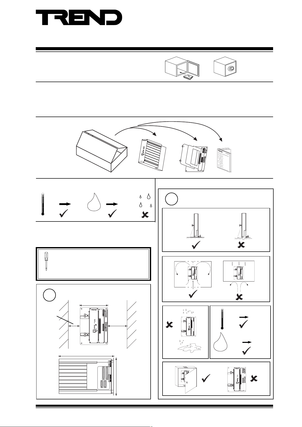
1 UNPACKING
2 STORING
-10 °C
(14 °F)
+50 °C
(122 °F)
H O
0
2
90 %RH
3 INSTALLATION INSTRUCTIONS
3.1 Installation - Mounting 1
3.2 Installation - Configuration 5
4 Replacing the Battery 9
5 Disposal 12
Installation
Instructions
TG200101
2
Requirements
a
3.1 Installation - Mounting
It is recommended that the installation should
comply with the HSE Memorandum of Guidance
on Electricity at Work Regulations 1989.
For USA install equipment in accordance with
National Electric Code.
1
20 mm
(0.79”)
Dimensions
155 mm (6.1”)
I Q 2 4 6
300 mm (11.81”)
b
0 °C
(32 °F)
0 %RH
OK
TX
RX
IQ 2 46
+45 °C
(113 °F)
90 %RH
0 V
POWER
24 Vdc
0 V
AUX
24 Vdc
OK
TX
RX
R+
R-
T+
T-
IQ 2 4 6
OK
TX
RX
IQ 2 46
0 V
POWER
24 Vdc
0 V
AUX
24 Vdc
OK
TX
RX
R+
R-
T+
T-
40 mm
(1.57”)
1
2
3
4
16
32
64
19K2
9K2
1K2
c
OK
TX
RX
IQ 24 6
d
H O
2
e
OK
TX
RX
IQ 24 6
210 mm (8.27”)
IQ246 Controller Installation Instructions TG200101 Issue 1/E 15/01/07
1
Page 2

IQ246 Installation Instructions
R+
RT+
T-
R+
R-
T+
T-
RR
TT
3.1 Installation - Mounting (continued)
Mounting
3
a
135 mm
(5.31”)
190 mm (7.48”)
4 holes
b
0 V
POWER
24 Vdc
0 V
AUX
24 Vdc
R+
R-
T+
T-
4 off
washers
∅ 6 mm (0.24”)
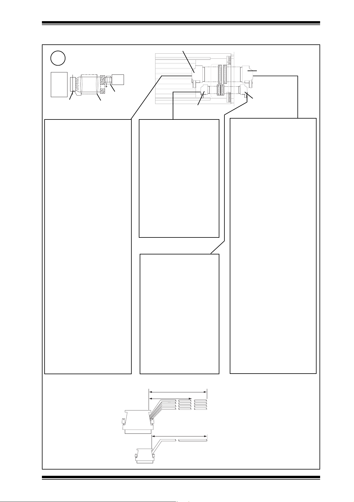
Connecting Power
4
24 Vdc - 1.7 A (max)
Earth (ground)
0 V
POWER
DO NOT APPLY
POWER
24 Vdc
0 V
AUX
24 Vdc
R+
R-
T+
T-
0 V
24 V
fuse
24 Vac - 72 VA transformer
~
O
1
WARNING: This apparatus must be earthed
0 V - - - - - - - -Earth, ground (recommended)
24 Vdc
controllers
may supply several
}
Earth (ground)
isolated transformer winding,
supply 1 controller only
fuse
24 Vac
}
(grounded) using power connector.
elbaCduab2k1duab6k9duab2k91seriWfo.oN
Connecting Network
5
2819nedleB
0 V
POWER
24 Vdc
0 V
AUX
24 Vdc
R+
R-
T+
T-
For more cable and connection information details refer to Network
7029nedleB
dnerT
dnerT
002/FH/22/1/1/PT
)1678nedleB(
002/FH/22/2/2/PT
)3278nedleB(
m0001
)sdy0901(
m0001
dy0901(
)s
m0001
)sdy0901(
m0001
)sdy0901(
m0001
)sdy0901(
m0001
)sdy0901(
m007
)sdy567(
m005
)sdy545(
m007
)sdy567(
m005
)sdy545(
m053
083(
)sdy
m052
)sdy072(
2
2
2
4
Engineering Manual 92-1735
4 wire method
Connect to T &
RR
T
R
T
R
T
R
T
R
2
T
R
T
R
T
R
T
R
TT
R of previous
R+
RT+
T-
R+
R-
T+
T-
RR
device, polarity
independent
terminate
screen at one
end of cable
Connect to T & R of
TT
next device, polarity
independent
IQ246 Controller Installation Instructions TG200101 Issue 1/E 15/01/07
2 wire method
Connect to T+,
T- of previous
device, polarity
independent
terminate screen
at transmit end
Connect to R+, R- of
next device, polarity
independent
Page 3
Installation Instructions IQ246
3.1 Installation - Mounting (continued)
37 Way 'D type' Male
Wire I/O Terminals
6
IQ246
D type shell
Earth Screens
Plant
cutback screen
cutback screen
15 Way 'D type' Female
37 Way 'D type' Female
15 Way 'D type' Male
Analog Inputs
J3 37 Way 'D type' Male
1
2
3
4
5
6
7
8
9
01
11
21
31
41
51
61
71
81
91
02
12
22
32
42
52
62
72
82
92
03
13
23
33
43
53
63
73
1nAdeR/AelbaC
❍
V0eulB/AelbaC
❍
❍
2nAwolleY/AelbaC
❍
3nAetihW/AelbaC
❍
V0kcalB/AelbaC
❍
❍
4nAteloiV/AelbaC
❍
5nAegnarO/AelbaC
❍
V0kniP/AelbaC
❍
❍
6nAeulB/BelbaC
❍
7nAneerG/BelbaC
❍
❍
8nAetihW/BelbaC
❍
9nAkcalB/BelbaC
❍
V0nworB/BelbaC
❍
❍
01nAegnarO/BelbaC
❍
11nAkniP/BelbaC
❍
V0deR/CelbaC
❍
❍
21nAneerG/CelbaC
❍
31nAwolleY/CelbaC
❍
❍
41nAkcalB/CelbaC
❍
51nAnworB/CelbaC
❍
V0teloiV/CelbaC
❍
❍
61nAkniP/CelbaC
❍
71nAdeR/DelbaC
❍
❍
81nAneerG/DelbaC
❍
91nAwolleY/DelbaC
❍
V0etihW/DelbaC
❍
❍
02nAnworB/DelbaC
❍
)2&1nA(V42neerG/AelbaC
)4&3nA(V42nworB/AelbaC
)6&5nA(V42deR/BelbaC
)8&7nA(V42wolleY/BelbaC
)01&9nA(V42teloiV/BelbaC
)21&11nA(V42eulB/CelbaC
)41&31nA(V42etihW/CelbaC
)61&51nA(V42egnarO/CelbaC
)81&71nA(V42eulB/DelbaC
)02&91nA(V42kcalB/DelbaC
Analog Outputs
J5 15 Way 'D type' Female
1
2
3
4
5
6
7
8
9
01
11
21
31
41
51
11pOdeR
❍
V0eulB
❍
21pOneerG
❍
31pOwolleY
❍
V0etihW
❍
41pOkcalB
❍
51pOnworB
❍
V0teloiV
❍
61pOegnarO
❍
V0kniP
❍
71pOkcalB/deR
❍
81pOneerG/eulB
❍
V0deR/neerG
❍
91pOdeR/wolleY
❍
02pOyerG
❍
Analog Outputs
J4 15 Way 'D type' Male
1
2
3
4
5
6
7
8
9
01
11
21
31
41
51
1pOdeR
❍
V0eulB
❍
2pOneerG
❍
3pOwolleY
❍
V0etihW
❍
4pOkcalB
❍
5pOnworB
❍
V0teloiV
❍
6pOegnarO
❍
V0kniP
❍
7pOkcalB/deR
❍
8pOneerG/eulB
❍
V0deR/neerG
❍
9pOdeR/wolleY
❍
01pOyerG
❍
Digital Inputs
J2 37 Way 'D type' Female
1
2
3
4
5
6
7
8
9
01
11
21
31
41
51
61
71
81
91
02
12
22
32
42
52
62
72
82
92
03
13
23
33
43
53
63
73
1giDdeR/AelbaC
❍
2giDeulB/AelbaC
❍
❍
❍
❍
❍
❍
❍
❍
❍
❍
❍
❍
❍
❍
❍
❍
❍
❍
❍
❍
❍
❍
❍
❍
❍
❍
❍
❍
❍
❍
❍
❍
❍
❍
❍
❍
giDV42neerG/AelbaC
3giDwolleY/AelbaC
4giDetihW/AelbaC
5giDkcalB/AelbaC
6giDnworB/AelbaC
7giDteloiV/AelbaC
8giDegnarO/AelbaC
giDV42kniP/AelbaC
9giDdeR/BelbaC
01giDeulB/BelbaC
11giDneerG/BelbaC
21giDwolleY/BelbaC
31giDetihW/BelbaC
41giDkcalB/BelbaC
giDV42nworB/BelbaC
51giDteloiV/BelbaC
61giDegnarO/BelbaC
71giDkniP/BelbaC
81giDdeR/CelbaC
91giDeulB/CelbaC
02giDneerG/CelbaC
giDV42wolleY/CelbaC
12giDetihW/CelbaC
22giDkcalB/CelbaC
32giDnworB/CelbaC
42giDteloiV/CelbaC
52giDegnarO/CelbaC
62giDkniP/CelbaC
72giDdeR/DelbaC
82giDeulB/DelbaC
giDV42neerG/DelbaC
92giDwolleY/DelbaC
03giDetihW/DelbaC
13giDkcalB/DelbaC
23giDnworB/DelbaC
Use Trend Cables CABLE/IQ246KIT
(see colour codes in tables above)
3 m (3.25 yds)
2 m (2 yds 6”)
37 W
3 m (3.25 yds)
15 W
IQ246 Controller Installation Instructions TG200101 Issue 1/E 15/01/07
A
B
C
D
3
Page 4

IQ246 Installation Instructions
3.1 Installation - Mounting (continued)
Connect Inputs
7
Digital inputs (digital inputs 1 to 32)
Dig'n'
+24 V DIG (24Vdc)
Analogue inputs (analogue inputs 1 to 20)
Voltage input
V (0 to 10V)
An'n'
0 V
Current input (loop powered)
➞ I (0 to 20 mA)
SIG
An'n'
24 V
Connect Outputs
8
Trend TP/1/1/22/HF/200 (Belden 8761) cable
recommended for voltage outputs
(analog outputs 1 to 20)
Bn
0V
WARNING: The wires may be connected to
hazardous voltages. Disconnect
power before attempting any wiring.
V
1
Load
Trend TP/1/1/22/HF/200 (Belden 8761) cable
recommended for all inputs
Thermistor input
An'n'
0 V
0V
Current input (external powered)
➞ I (0 to 20 mA)
SIG
An'n'
0 V
0V
Additional Relay Modules
IQ246
Relay
Module
SRMV =
2SRM =
2RM =
3RM =
6RM =
nRM
x 1
x 2
x 2
x 3
x 6
T
1
(R/L, H/L)
(HCM/TRM)
Connect Auxiliary Output Supply
9
(if required)
For relays, NDP
e.g.
0 V
POWER
24 Vdc
0 V
AUX
24 Vdc
R+
R-
T+
T-
4
24 Vdc Auxiliary Output Supply
0 V
24 V
0 V
Imax = 500 mA
24 Vdc
IQ246 Controller Installation Instructions TG200101 Issue 1/E 15/01/07
I Q 2 4 6
0 V
2 4 V
0 V
O p ' n '
2 R M
2 4 V
0 V
I N
Page 5

Installation Instructions IQ246
3.2 Installation - Configuration
Set Network Address
1
Set Network Baud Rate
2
O
N
1 2 3 4 5 6 7 8 9 1 0
ç
1
2
4
8
1 6
3 2
6 4
1 9 K 2
9 K 6
1 K 2
address
1, 4 to 9, 11 to 119
0, 2, 3,10 or >119
O
N
1 2 3 4 5 6 7 8 9 1 0
ç
1
2
4
8
1 6
3 2
6 4
1 9 K 2
9 K 6
1 K 2
e.g. Address = 2 + 16 = 18
NOT SET
Address = A
= A
/
e.g. 19k2 baud
SET
1 9 k 2
= A
= A
/
IQ246
9 k 6
= A
/
1 k 2
Remove Board
3
a
unscrew 4 screws
bc
Caution: This unit contains static sensitive devices.
Suitable anti-static precautions should be taken
throughout this operation to prevent damage
to the unit.
BS EN100015/1 Basic Specification: protection of
electrostatic sensitive devices.
Baud Rate = B
= B
= B
= B
= B
IQ246 Controller Installation Instructions TG200101 Issue 1/E 15/01/07
5
Page 6

IQ246 Installation Instructions
O
1
3.2 Installation - Configuration (continued)
Set Analogue Input Channel Links
4
J20
1
J22J21
3
2
J23
J25
J27
8
J11
12
J14
J15
J16
5
4
J26
7
6
J28
9
J29
10
J10
11
J12
13
J13
14
J17
15
18
J18
16
17
19
J19
20
An 'n'
V T
1
Replace Board
5
b
a
Plug in Main Controller Unit
6
a
slot
board
b
c
c
tighten 4 screws
screw in thumb knobs
0 V
POWER
24 Vdc
0 V
AUX
24 Vdc
OK
TX
RX
R+
R-
T+
T-
I Q 2 4 6
Plug in Ribbon Cable
7
8
Switch on
6
IQ246 Controller Installation Instructions TG200101 Issue 1/E 15/01/07
Page 7

Installation Instructions IQ246
IQ246
?
IQ246
IQ246
?
3.2 Installation - Configuration (continued)
9
10
Check Controller
Check Network
OK
TX
RX
0 V
POWER
24 Vdc
0 V
AUX
24 Vdc
OK
TX
RX
R+
R-
T+
T-
a (power)
Check
supply
b (watchdog)
I Q 2 4 6
IQ
Faulty
aTX
0 V
POWER
24 Vdc
0 V
AUX
24 Vdc
R+
R-
T+
T-
bRX
c OK
TX- TX+
11
LAN
SET
X. IQ2
IQ246
OK
RX+
RX-
Configure
I Q 2 4 6
IQ Faulty
LAN
TX- TX+ RX- RX+
OR
IQ246
Network Address
0,2,3 or >119
OK
Check network cabling for
short circuits with a
multimeter (NOT Megger)
Check baud rate .
Switch on other nodes until
O
1
faulty node is found ( OK
). Correct fault.
IQ Configuration Manual 90-1533
IQ246 Data Sheet TA200100
SET Manual TE200147
IQ246
9 Way 'D
type' Female
RJ11
Cable/EJ101442
IQ246 Controller Installation Instructions TG200101 Issue 1/E 15/01/07
7
Page 8

IQ246 Installation Instructions
I Q 2 4 6
S
IQ246
IQ246
S
3.2 Installation - Configuration (continued)
12
a
13
a
14
Test Digital Inputs
b
O
1
Test Analogue Inputs
b
O
1
Test Outputs
c
O
1
c
O
1
d
OFF
ON
d
ΔT = X
a
15
SET
IQ246
O
1
Backup
X.IQ2
b
c
O
1
SET Manual TE200147
IQ246
OR
9 Way 'D type'
Female
d
Cable/EJ101442
VB
IQ246
RJ11
16
8
Close Panel
OK
TX
RX
IQ 2 4 6
IQ246 Controller Installation Instructions TG200101 Issue 1/E 15/01/07
Page 9

Installation Instructions IQ246
4 REPLACING THE BATTERY
1
SET
IQ246
2
Upload Strategy
X.IQ2
Switch Off
O
1
IQ246
3
OR
9 Way 'D
type' Female
Open Panel
Cable/EJ101442
OK
TX
RX
IQ 2 4 6
SET Manual TE200163
IQ246
RJ11
WARNING: Opening the panel
may expose
dangerous
voltages.
417-IEC-5036
WARNING: The connecting
leads may be
connected to
supplies. Isolate
before touching.
4
6
Remove I/O Connectors
Remove Main Module
5
Unscrew Thumb Knobs
0 V
POWER
24 Vdc
0 V
AUX
24 Vdc
OK
TX
RX
I Q 2 4 6
R+
R-
T+
T-
Pull until it stops then pull continuously, to unplug ribbon cable
connector from backplate
IQ246 Controller Installation Instructions TG200101 Issue 1/E 15/01/07
9
Page 10

IQ246 Installation Instructions
4 REPLACING THE BATTERY (continued)
Remove Board
7
unscrew 4 screws
b
8
Replace Battery
Saft LM2450 3V
a
Caution: This unit contains static sensitive devices.
Suitable anti-static precautions should be
taken throughout this operation to prevent
damage to the unit.
BS EN100015/1 Basic Specification: protection of
electrostatic sensitive devices.
c
Warning: This lithium battery
must not be recharged,
+
disassembled, burnt or short
circuited. Misuse may cause
explosion or fire. Dispose of
carefully. Refer to Health and
Safety Executive Guidance
Note GS43.
Note the Network Address
9
and Baud Rate
O
N
1 2 3 4 5 6 7 8 9 1 0
ç
1
2
4
8
1 6
3 2
6 4
1 9 K 2
9 K 6
1 K 2
e.g. Address = 2 + 16 = 18
NOT SET
A D D R E S S
1 9 k 2
B A U D
SET
9 k 6
1 k 2
10
a
b
c
Replace Board
slot
board
tighten 4 screws
10
IQ246 Controller Installation Instructions TG200101 Issue 1/E 15/01/07
Page 11

Installation Instructions IQ246
O
1
4 REPLACING THE BATTERY (continued)
11
12
Plug in Main Controller Unit
Plug in Ribbon Cable
13
14
Switch On
Wait
screw in thumb knobs
0 V
POWER
24 Vdc
0 V
AUX
24 Vdc
OK
TX
RX
I Q 2 4 6
R+
R-
T+
T-
Switch Off
15
O
1
O
1
16
19
Set all Switch Poles to Zero
O
N
1 2 3 4 5 6 7 8 9 1 0
ç
Set Network Address
1
2
4
8
1 6
3 2
6 4
1 9 K 2
9 K 6
1 K 2
ADDRESS = 0
A D D R E S S
BAUD = 0
B A U D
10s
Switch On
17
O
N
1 2 3 4 5 6 7 8 9 1 0
ç
1
2
4
8
1 6
3 2
6 4
1 9 K 2
9 K 6
1 K 2
e.g. Address = 2 + 16 = 18
NOT SET
SET
18
Wait for
Relays
'click'
address
IQ246 Controller Installation Instructions TG200101 Issue 1/E 15/01/07
Address = A
1, 4 to 9, 11 to 119
0, 2, 3, 10 or >119
= A
/
= A
= A
/
IQ246
= A
/
11
Page 12

IQ246 Installation Instructions
4 REPLACING THE BATTERY (continued)
O
N
1 2 3 4 5 6 7 8 9 1 0
ç
1
2
4
8
1 6
3 2
6 4
1 9 K 2
e.g. 19k2 baud
9 K 6
1 K 2
1 9 k 2
= B
9 k 6
1 k 2
20
Set Network Baud Rate
21
22
Download Strategy
SET
X.IQ2
IQ246
Connect I/O
OR
9 Way 'D type'
Female
Cable/EJ101442
Baud Rate = B
IQ246
RJ11
= B
SET Manual TE200163
IQ246
23
= B
= B
Close Panel
OK
TX
RX
IQ 2 4 6
5 DISPOSAL
WEEE Directive :
At the end of their useful life the packaging,
product, and batteries should be disposed of
by a suitable recycling centre.
Do not dispose of with normal household waste.
Do not burn.
Manufactured for and on behalf of the Environmental and Combustion Controls Division of Honeywell Technologies Sàrl, Ecublens, Route
du Bois 37,Switzerland by its Authorized Representative, Trend Control Systems Limited.
Trend Control Systems Limited reserves the right to revise this publication from time to time and make changes to the content
hereof without obligation to notify any person of such revisions or changes.
Trend Control Systems Limited
P.O. Box 34, Horsham, West Sussex, RH12 2YF, UK. Tel:+44 (0)1403 211888 Fax:+44 (0)1403 241608 www.trend-controls.com
Trend Control Systems USA
6670 185th Avenue NE, Redmond, Washington 98052, USA. Tel: (425)897-3900, Fax: (425)869-8445 www.trend-controls.com
12
IQ246 Controller Installation Instructions TG200101 Issue 1/E 15/01/07
 Loading...