

Page 1
IQ241/242 Node Fixing Kit
Important: Retain these instructions
SHEET 1: Installation Instructions - Part 1
Installation Instructions - Part 1
KIT/NODE/IQ241
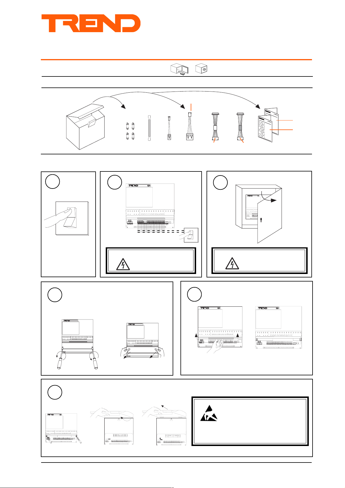
1.1 Unpacking
EJ103082
EARTH
CABLE/EJ103087
POWER
1.2 Installing a Node in IQ241/242 using KIT/NODE/IQ241
Isolate I/O
2
WARNING: The connecting leads may
be connected to supplies.
Isolate before touching.
1
Switch Off
O
I
EJ103086
NETWORK
CABLE/EJ103817
RS232/TMNE
O
I
25 W
Male
red
sheath
Molex
1
3
WARNING: Opening the panel may
25 W
Female
black
sheath
Molex
CABLE/EJ100179A001
RS232/CNC2, PNC2
Open Panel
expose dangerous voltages.
Installation Instructions,
1
2
417-IEC-5036
KIT/NODE/IQ241
TG200672
Sheet 1
Sheet 2
Remove ENCLS/CMTRAY cover
4
if ENCLS/CMTRAY fitted
a undo screws
1 3 "
Remove Lid
6
a undo screws
b lift lid
b lift off cover
1 3 "
c remove lid
5
Lift Flap
Caution: This unit contains static sensitive
devices. Suitable anti-static
precautions should be taken
throughout this operation to prevent
damage to the unit.
BS EN100015/1 Basic Specification: protection of
electrostatic sensitive devices.
KIT/NODE/IQ241 IQ241/242 Node Fixing Kit Installation Instructions TG200672 Issue 1/A 23/5/03 1 - 1
Page 2
KIT/NODE/IQ241 Installation Instructions - Part 1
J7
ET1
J16
Dev B
J15
Dev A
J9J8
Lan B Lan A
Modem
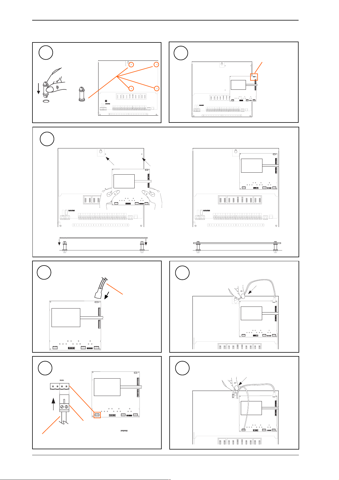
1.2 Installing a Node in IQ241/242 using KIT/NODE/IQ241 continued
Install Nylon Support Posts
7
Orientate Board
8
earth tag
(top right
ab
hand corner)
4 off
Fit Board onto Posts
9
J9J8
Lan B Lan A
ET1
J16
Dev B
Modem
J15
Dev A
J7
ab
ET1
J16
Dev B
Modem
J15
Dev A
J7
J9J8
Lan B Lan A
Push on
Nylon Post
Connect Earth to Node Board
10
Connect Power Cable to Node Board
12
0V
~
~
Ensure socket is connected to correct
terminal pins (+, -, or , 0V)
cable EJ103087 supplied
1 - 2
Node Controller
Node Controller in position
Feed Earth Cable through slot
ET1
J9J8
Lan B Lan A
Feed Power Cable through slot
ET1
J9J8
Lan B Lan A
J16
Dev B
Modem
J15
Dev A
J7
J16
Dev B
Modem
J15
Dev A
J7
J9J8
Lan B Lan A
Push on
11
Dev B
Dev A
cable EJ103082
supplied
ET1
J16
Dev B
Modem
J15
Dev A
J7
J9J8
Lan B Lan A
13
ET1
J16
Modem
J15
J7
KIT/NODE/IQ241 IQ241/242 Node Fixing Kit Installation Instructions TG200672 Issue 1/A 23/5/03
Page 3
Installation Instructions - Part 1 KIT/NODE/IQ241
J38 XNC
J7
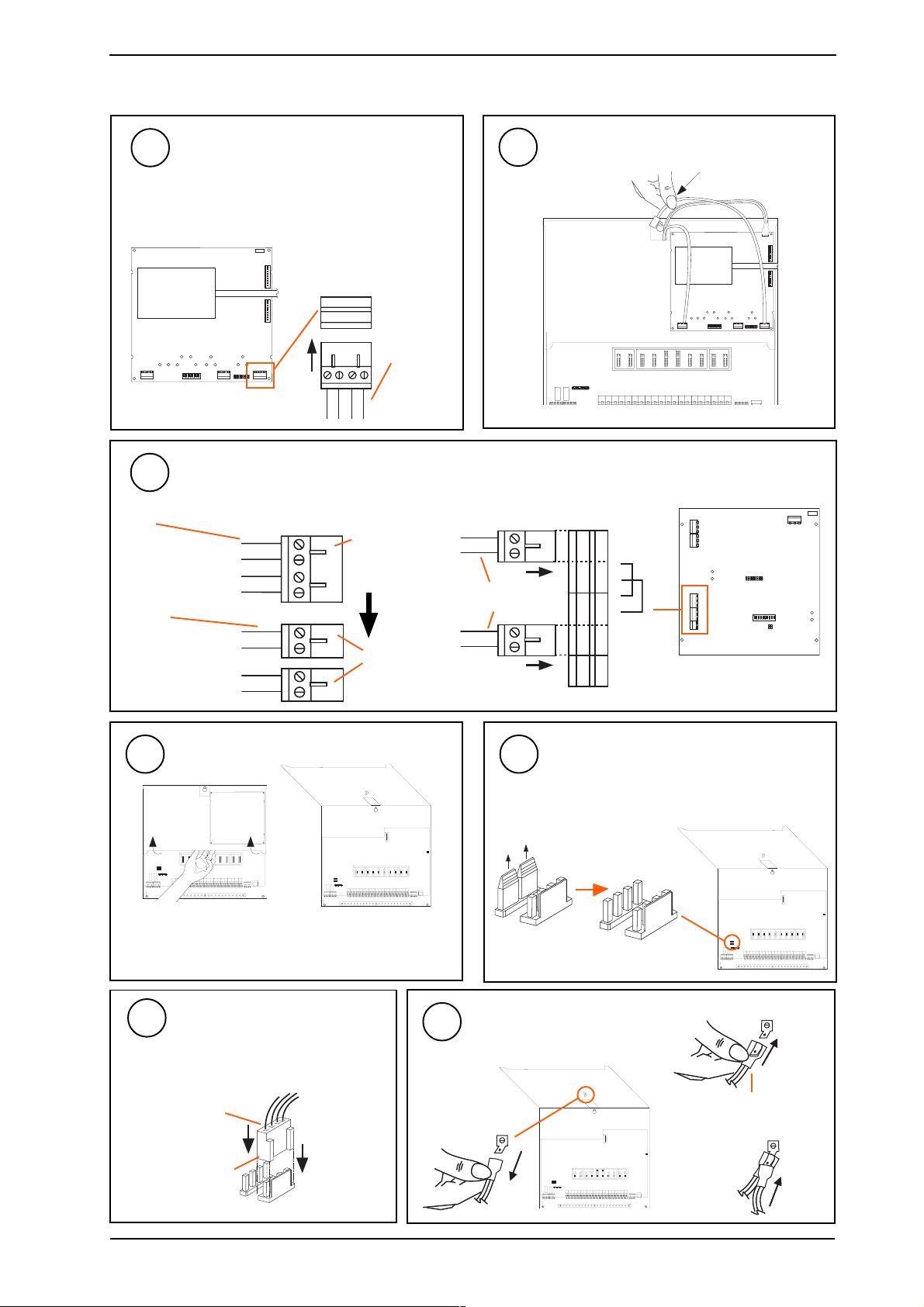
1.2 Installing a Node in IQ241/242 using KIT/NODE/IQ241 continued
Connect Local Network to Node Board
14
Not ANC, AND, MNC, TMN if on internetwork
Not INC2 if used as internetwork repeater
(dumb/normal - normal, address>=100).
For LINC see step 22
(4 wide)
J9J8
Lan B Lan A
ET1
J16
Dev B
Modem
J15
Dev A
J7
Lan A
T-R-R+
T+
cable
EJ103087
supplied
Connect Local Network to Node Board (8 wide)
16
For LINC only (if not used as internetwork Lan extension node (address<100))
cable
EJ103086
supplied
cable
EJ103086
modified
local network
(a) Rewire cable cable EJ103086
TT+
R-
Remove
4 way
plug
R+
TT+
RR+
Wire
2 x 2
way
plugs
Feed Cable through slot
15
(b) Connect cable
cable EJ103086
rewired
TT+
RR+
TT+
RR+
SCN
SCN
ET1
J16
Dev B
Modem
J15
Dev A
J7
J9J8
Lan B Lan A
POWER
J15
J11
J12
LAN
J9 J17
J1
9
10
Lift Hinged Plate
17 18
pull off links
Connect Local Network Cable
Not ANC, AND, MNC, TMN if on
19
internetwork.
Not INC2 if used as internetwork repeater
(dumb/normal=normal, address>100)
cable
EJ103086
supplied
polarised
J7
connector
J38 XNC
(a) Remove earth cable already fitted
Connect Earth Cable
20
to tag
Remove Network Links
Not ANC, AND, MNC, TMN if on internetwork.
Not INC2 if used as internetwork repeater
(dumb/normal=normal, address>100)
J7
J38 XNC
(b) Push on receptacle
cable EJ103082 supplied
(c) Replace existing earth
connection
KIT/NODE/IQ241 IQ241/242 Node Fixing Kit Installation Instructions TG200672 Issue 1/A 23/5/03 1 - 3
Page 4

KIT/NODE/IQ241 Installation Instructions - Part 1
1.2 Installing a Node in IQ241/242 using KIT/NODE/IQ241 continued
21
cable
EJ103087
supplied
Connect Power Cable
XNC
PWR
For ANC, AND, XN28, MNC or LINC on internetwork (for LINC
connection see step 22d)
For INC2 if used as internetwork repeater (dumb/normal = normal,
address>100)
Connect Internetwork and Internetwork
22
Segment A to Node Board
a
J40
O
DO NOT SWITCH ON
1
b c connect 4 wide d connect 8 wide
LINC
J15
J11
J12
LAN
J9 J17
(Lan A)
Internetwork Segment A (INC2)
Internetwork (TMN)
ET1
J9J8
Lan B Lan A
Lan A
T-R-R+
T+
J16
Dev B
Modem
J15
Dev A
J7
internetwork
cable
POWER
J1
9
10
T T +
R -
R +
T T +
R -
R +
Connect Internetwork and Internetwork Segment B to Node Board
23
Internetwork for INC, INC2
Internetwork Segment B for INC2 if used as internetwork repeater (dumb/normal = normal, address>=100)
a b
1 - 4
J 9J 8
L a n B La n A
E T 1
J 1 6
D e v B
M o de m
J 1 5
D e v A
J 7
c
KIT/NODE/IQ241 IQ241/242 Node Fixing Kit Installation Instructions TG200672 Issue 1/A 23/5/03
Lan B
T-R-R+
T+
either pierce grommet
or use copex gland
(Lan B)
Internetwork
Internetwork Segment B if INC2
used as internetwork repeater
internetwork cable
Page 5

Installation Instructions - Part 2
KIT/NODE/IQ241
IQ241/242 Node Fixing Kit
SHEET 2: Installation Instructions - Part 2
2 Installing a Node in IQ241/242 using KIT/NODE/IQ241 - Part 2
Connect RS232 to Node Board
24
for CNC, PNC, ANC, XNC+, XN28, AND, CNC2, PNC2, TMNE
a
CNC2, PNC2
25 Way D type
female
J 9J 8
L a n B L a n A
E T 1
J 1 6
D e v B
M od em
J 1 5
RS232 (Dev B Modem)
D e v A
J 7
black sheath
CABLE/EJ100179A001
supplied
1
b
10 Way Molex Socket
(pins 2 linked to 4, 3
linked to 5)
polarised
TMNE
25 Way D type
male
c
2
ET1
J16
Dev B
Modem
J9J8
Lan B Lan A
J15
J7
1
RS232 (Dev B Modem)
Dev A
red sheath
CABLE/EJ103817
supplied
10 Way Molex Socket
polarised
Connect Device to IQ241/242 RS232/Modem Connector
25
KIT/NODE/IQ241 IQ241/242 Node Fixing Kit Installation Instructions TG200672 Issue 1/A 23/5/03 2 - 1
CNC2
9 Way D type Female
CABLE/58-0750
25 Way D type Male
PNC2
25 Way D type Male
special cable, pins 3,7,20
connected straight through
25 Way D type Male
TMNE
Modem/
Terminal
Adaptor
25 Way D type Male
CABLE/58-2894
25 Way D type Female
Page 6

KIT/NODE/IQ241 Installation Instructions - Part 2
J 7
E T 1
J 1 6
D e v B
J 1 5
D e v A
J 9J 8
L a n B L a n A
M o de m
2 Installing a Node in IQ241/242 using KIT/NODE/IQ241 - Part 2 (continued)
Route Special Device Cables
26
(a) Remove TMNH adaptor plug
(c) Knock out hole
(e) Replace TMNH adaptor plug
For ENC, MNC, TMNH
for TMNH only
for TMNH only
(b) Identify cable
e.g. TMNH
Integral modem
(TMNH only)
(d) Route cable through hole
(f) Connect to device
cable
either pierce grommet
or use copex gland
MNC, TMNH
PSTN
Link Network Connectors
27
(b) Route cables through hole
If ANC, AND, XN28, MNC, TMN, is fitted and
IQ241/242 is not networked (stand alone)
T- T+ R- R+ T- T+ R- R+
LAN
earth
bar
either pierce grommet
or use copex gland
Connect to LonWorks
28
(a) Knock out hole
(c) Connect Lon cables
For LINC only
SCN
LanA
LanB
SCN
LanA
LanB
POWER
J15
J11
J12
LAN
J9 J17
J1
9
10
2 - 2
29
Check Settings
if appropriate
(a) Check network baud rate.
(b) Check network address and dumb/normal switch.
Node Controller
Data Sheet
(c) Check 2nd network/device baud rate.
KIT/NODE/IQ241 IQ241/242 Node Fixing Kit Installation Instructions TG200672 Issue 1/A 23/5/03
Page 7

Installation Instructions - Part 2 KIT/NODE/IQ241
O
1
I Q 2 3 x
?
2 Installing a Node in IQ241/242 using KIT/NODE/IQ241 - Part 2 (continued)
30
32
Close Hinged Plate
Check Node Controller
J9J8
Lan B Lan A
31
ET1
J16
Dev B
Modem
J15
Dev A
J7
TMN type board shown
Check node data sheet for location of LEDs on other boards
a PWR ON
(green)
b W/DOG
(red)
Switch On
Check supply
Node Faulty
Check Trend Lan and Internetwork sections
33
Do separate check for each Lan/Internetwork segment
TMN type board
shown
Check node data
sheet for location
of LEDs on other
boards
LAN
T-
R-
T+
R+
OK
Node Faulty
T X - T X + R X - R X +
J9J8
Lan B Lan A
LAN
node
ET1
J16
Dev B
Modem
J15
Dev A
J7
aRX
(yellow)
bTX
(yellow)
node
I Q 2 3 x
?
c OK
(green)
Network Address Invalid
0, 2, 3 or >119
node
OK
Check baud rate . Check
network cabling for short circuits
with a multimeter (NOT Megger)
O
I
Power up other nodes until
faulty node is found
(OK ). Correct fault.
34
Switch Off
35
Close Flap
O
I
KIT/NODE/IQ241 IQ241/242 Node Fixing Kit Installation Instructions TG200672 Issue 1/A 23/5/03 2 - 3
Page 8

KIT/NODE/IQ241 Installation Instructions - Part 2
2 Installing a Node in IQ241/242 using KIT/NODE/IQ241 - Part 2 (continued)
36
a hook on lid
37
Replace Lid
Replace
ENCLS/CMTRAY Cover
if ENCLS/CMTRAY fitted
I Q 2 4 1
b close lid
Close Panel
38
I Q 2 4 1
Reconnect Supply to I/O
39
c tighten screws
O
1
Switch on
40
(INC, INC2, ANC, AND, XN28, MMNC, TMN,
ENC, XNC+, LINC)
O
1
Trend Control Systems Ltd reserves the right to revise this publication from time to time and make changes to the content
hereof without obligation to notify any person of such revisions or changes.
Configure
41
if required
Node Installation Instructions
Test System
42
Node Installation Instructions
Trend Control Systems Ltd. P.O. Box 34 Horsham Sussex RH12 2YF Tel:+44 (0)1403 211888 Fax:+44 (0)1403 241608 www.trend-controls.com
2 - 4
KIT/NODE/IQ241 IQ241/242 Node Fixing Kit Installation Instructions TG200672 Issue 1/A 23/5/03
 Loading...