

Page 1
Important: Retain these instructions
1 3
1 3
1234 5678 910
RX
TX
OK
ADD RESS BAUD
SW 4
A
D
DP
C
B
J16
De v B
J15
De v A
Installation Instructions - Fixing
IQ23x
Series Controllers
CONTENTS
1.1 Unpacking 1 - 1
1.2 Storing 1 - 1
1.3 Installation - Fixing 1 - 1
2 Installation - Configuration 2 - 1
3.1 Fitting a Remote 2-line Display 3 - 1
3.2 Connecting to a PC via Supervsior Port 3 - 1
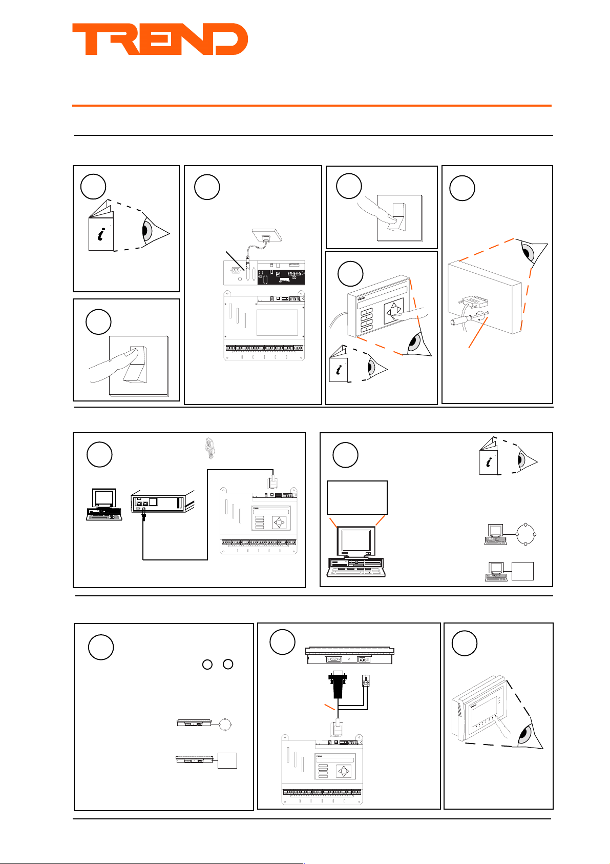
SHEET 1: Installation Instructions - Fixing
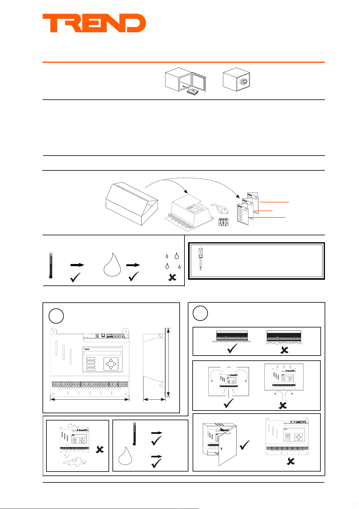
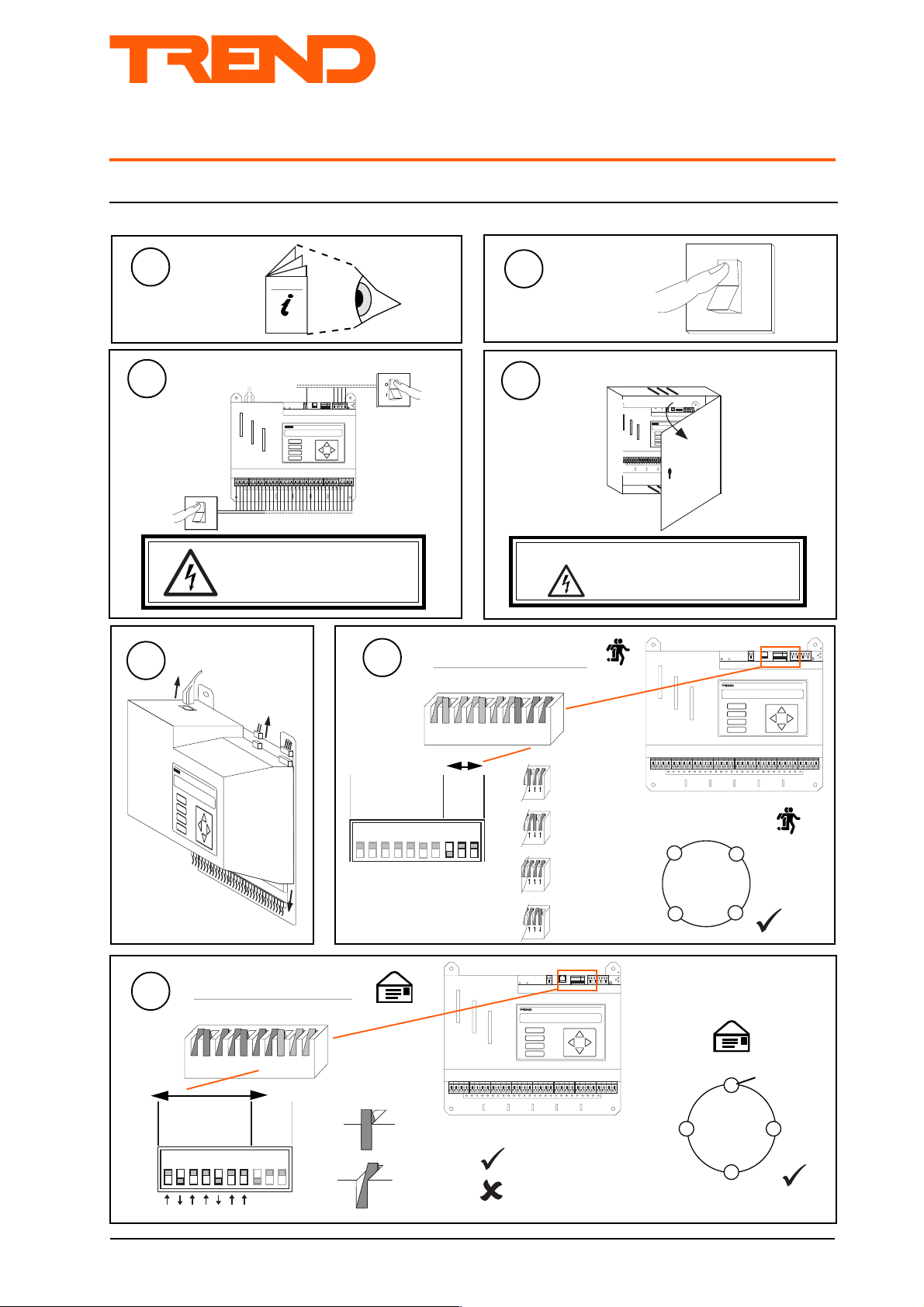
1.1 Unpacking
1.2 Storing
-10 °C
+50 °C
0
90 %RH
H2O
3.3 Connecting to an NDP via Supervsior Port 3 - 1
3.4 Mounting in an Enclosure,ENCLS/... 3 - 2
3.5 Replacing the Battery 3 - 2
3.6 Zero Address/Baud Rate Switch Reset 3 - 4
4 Replacing IQ111 4 - 1
5 Replacing IQ111+ 5 - 1
6 Replacing IQ131 6 - 1
7 Replacing IQ131+ 7 - 1
8, 9 Installing a Node Board from a Replaced Controller 8 - 1
1
IQ23x Installation
Instructions TG200539
Sheet 1: Fixing
Sheet 2: Configuration
Sheet 3: Options
It is recommended that the installation should
comply with the HSE Memorandum of Guidance
on Electricity at Work Regulations 1989.
1.3 Installation - Fixing
1
c
Dimensions
A
B
C
D
339 mm
RX
ADD RES S BA UD
OK
123 456 7891 0
TX
SW 4
DP
A
B
C
D
BA U D
AD D R ES S
1284163264
1K 2
9K 6
19 K2
2
R X
O K
T X
D P
299 mm
b
Requirements
a
1
! N
2 3 4 5 6 7 8 9 10 1 1 1 2 13 1 4 1 5 16 17 18 19 20
A
B
C
D
ADDR ESS BA UD
1234 567891 0
SW4
1
2 3 4 5 6 7 8 9 10 1 1 12
RX
OK
TX
DP
V
! N
1
2 3 4 5 6 7 8 9 10 1 1 1 2 1 3 14 15 1 6 1 7 1 8 19 20
V
1
2 3 4 5 6 7 8 9 10 1 1 1 2
RX
ADD RESS BAUD
OK
1234 5678 910
TX
SW4
DP
A
B
C
D
93 mm
RX
BAU D
AD DRE SS
OK
1284163264
1K2
9K6
e
d
0 °C +45 °C
H2O
0 %RH
90 %RH
19K2
TX
D P
A
B
C
D
IQ23x Series Controllers Installation Instructions TG200539 Issue 1/A 26/3/02 1 - 1
Page 2
IQ23x Installation Instructions - Fixing
1.3 Installation - Fixing (continued)
3
a
4
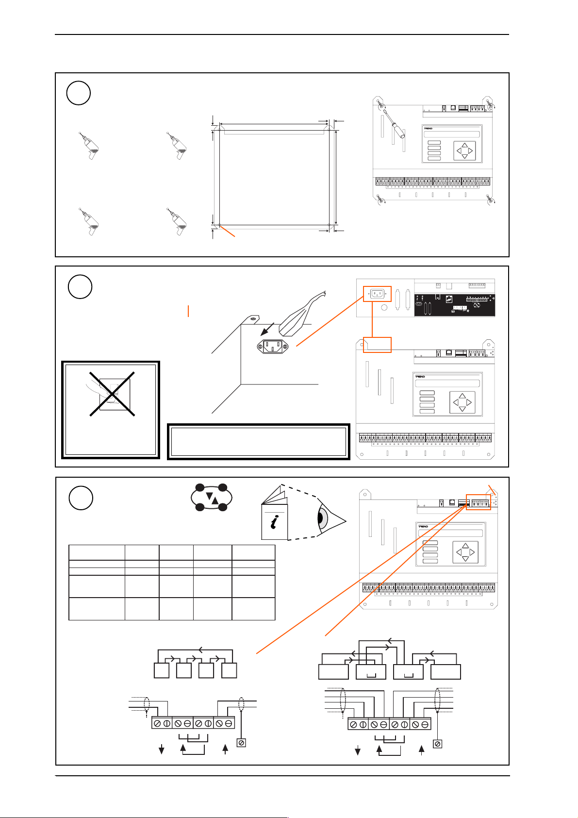
Mounting
Connecting Power
IQ Consumption > 60 VA
230 Vac +15% -10%
50 to 60 Hz
b
dimensions in mm
308
14
AD D RE S S
1284163264
12
A
B
C
D
263
12
4 x Ø 6 mm
cable supplied
14
A U X
2 4 V
2 30 V
R D S
R S 2 3 2/ M O D E M
AD D R ES S
1284163264
R X
R X
BA U D
O K
1K 2
9K 6
19K 2
TX
D P
R x
T + T- R + R -
O K
T x
R +
T +
T -
R -
BA U D
R X
O K
1K 2
9K 6
19 K2
T X
O
1
DO NOT APPLY
POWER
5
Terminal size 0.5 to 2.5 mm
Connect Network
elbaCduab2k1duab6k9duab2k91seriWfo.oN
2819nedleBm0001m0001m0072
7029nedleBm0001m0001m0052
dnerT
)1678nedleB(
dnerT
)3278nedleB(
m0001m007m0532
005/FH/22/1/1/PT
m0001m005m0524
005/FH/22/2/2/PT
WARNING: This apparatus must be
earthed (via power lead)
Network Engineering
Manual 92-1735
2
2 wire 4 wire
A
B
C
D
A
B
C
D
polarity independent
D P
M3 earth stud
BA U D
AD D R ES S
1284163264
1K 2
9K 6
19 K2
R X
O K
T X
D P
1 - 2
R T R T R T R T
T
T
X
T -T +R -R + T -T +R -R +
-+-+ -+-+
e a r t h
s t u d
R T R T R T R T R T R T R T R T
R
R
T
T
X
T -T +R -R + T -T +R -R +
-+-+ -+-+
e a r t h
s t u d
T
T
R
R
IQ23x Series Controllers Installation Instructions TG200539 Issue1/A 26/3/02
Page 3
Installation Instructions - Fixing IQ23x
1.3 Installation - Fixing (continued)
R X
BA U D
6
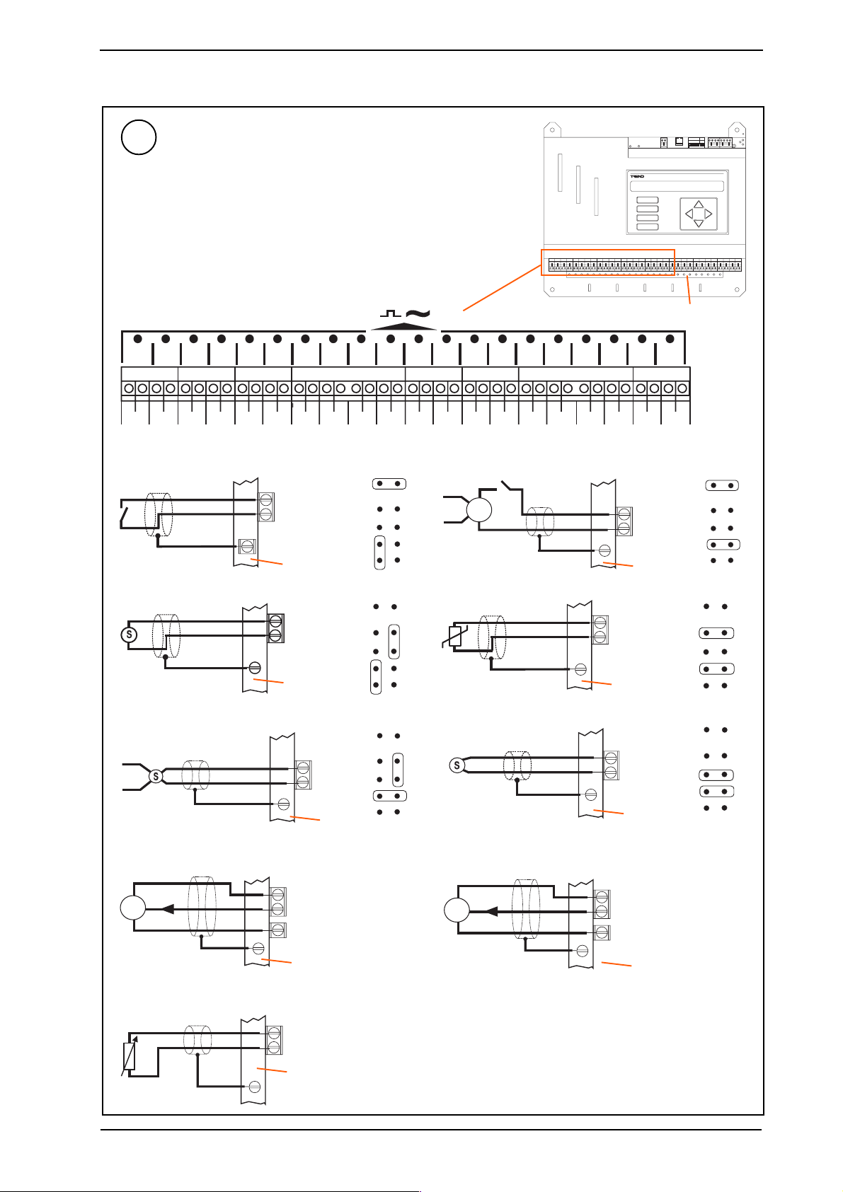
Connect Inputs
Trend TP/1/1/22/HF/500 (Belden 8761) cable
recommended for all inputs
Terminal size 0.5 to 2.5 mm
2
AD D R ES S
1284163264
A
B
C
D
O K
1K 2
9K 6
19 K2
T X
D P
Universal Inputs IN1 to IN20
1 2 3 4 5 6 7 8 9 1 0 1 1 1 2 1 3 1 4 1 5 1 6 1 7 1 8 1 9 2 0
I N 1
C
I N 2CI N 3CI N 4CI N 5
Digital input (loop powered)
Current input (loop powered)
( 0 t o 2 0 m A )
®
1
S I G
2 4 V
C
I N 6CI N 7CI N 8
I N n
C ( 2 4 V )
earth flange
I N n
C ( 2 4 V )
earth flange
C
I N 9
C
C
C
I N 1 1
I N 1 0
I N 1 2CI N 1 3
C
I N 1 4CI N 1 5CI N 1 6
C
I N 1 7
C
C
I N 1 8
Digital input (external powered)
D
+ 2 4 V
2 4 V
D C
-
0 V
Thermistor input
I
0 V
I N n
C ( 0 V )
earth flange
I N 1 9CI N 2 0
I N n
C ( 0 V )
earth flange
earth flange
C
D x
T
Current input (external powered)
( 0 t o 2 0 m A )
®
1
S I G
0 V
S i g n a l
5 V
S
0 V
if LKE/10mA fitted
1 0 m A
¬
0 V
I N n
C ( 0 V )
earth flange
I N n
C ( 5 V )
0 V
earth flange
I N n
C ( 0 V )
earth flange
Voltage input
I x
V ( 0 t o 1 0 V )
I N n
0 V
C ( 0 V )
V
earth flange
if LKE/15V fittedif LKE/5V
S i g n a l
1 5 V
S
0 V
I N n
C ( 1 5 V )
0 V
earth flange
IQ23x Series Controllers Installation Instructions TG200539 Issue 1/A 26/3/02 1 - 3
Page 4
IQ23x Installation Instructions - Fixing
1.3 Installation - Fixing (continuedd
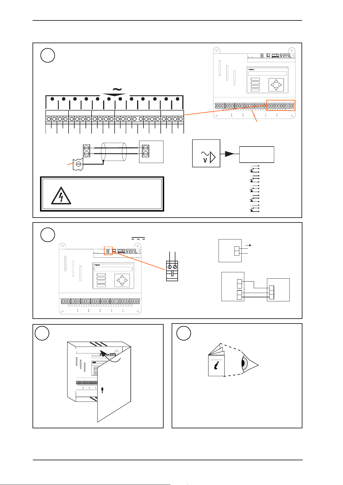
7
Connect Outputs
Trend TP/1/1/22/HF/500 (Belden 8761) cable
recommended for voltage outputs
Terminal size 0.5 to 2.5 mm
2
Analogue Voltage Outputs, B1 to B12
V
1 2 3 4 5 6 7 8 9 1 0 1 1 1 2
B 1
0 V
0 V 0 V 0 V 0 V 0 V 0 V 0 V 0 V 0 V 0 V 0 V
B 2 B 3 B 4 B 5
B 6 B 7 B 8
B n
0 V
earth flange
WARNING: The wires may be connected to hazardous
voltages. Disconnect power before
attempting any wiring.
B 9
l o a d
B 1 0 B 1 1
B 1 2
Additional Relay Modules
I Q 2 3 x
A
B
C
D
R e l a y
M o d u l e
S R M V =
2 S R M =
2 R M =
3 R M = x 3
6 R M = x 6
BA U D
AD D R ES S
1284163264
19 K2
earth flange
n R M
x 1
x 2
x 2
(R/L, H/L)
(HCM/TRM)
R X
O K
1K 2
9K 6
T X
D P
9
Connect Auxiliary Supply 24 V
8
A
B
C
D
Close Panel
AD DR ES S B AU D
12 34 56 78 910
SW 4
A
B
C
D
500 mA
AD D R ES S
1284163264
O K
1K 2
9K 6
19 K2
T X
D P
AUX
R X
BA U D
Terminal size 0.5 to 2.5 mm
0 V 24 V
10
RX
OK
TX
J1 6
D P
D ev B
J1 5
D ev A
Configure/Commission
e.g.
2
I Q 2 3 x
2 4 V
+
-
Imax = 500 mA
I Q 2 3 x
+
2 4 V
-
0 V
B n
2 R M
2 4 V
0 V
I N
2
IQ23x Installation Instructions - Sheet 2: Configuration
1 - 4
IQ23x Series Controllers Installation Instructions TG200539 Issue1/A 26/3/02
Page 5
Installation Instructions - Configuration
12481 6
3 2
6 4
1 9 K 2
9 K 6
1 K 2
Series Controllers
SHEET 2: Installation Instructions - Configuration
2 Installation - Configuration
IQ23x
Fix Unit
1
IQ23x Installation
Instructions - Sheet 1:
Fixing
Isolate I/O, Network
3
O
I
WARNING: The connecting
leads may be connected to
supplies. Isolate before touching.
Disconnect I/O
5
Switch off
1
2
O
I
Open Panel
4
RX
BA UD
AD DR ESS
OK
1284163264
1K2
9K6
19K 2
TX
D P
A
B
C
D
Set the Network Baud Rate
6
2
RX
ADD RES S B AUD
OK
123 456 789 10
TX
SW 4
J1 6
DP
De v B
J1 5
A
B
C
De v A
D
WARNING: Opening the panel may expose
dangerous voltages.
417-IEC-5036
A
B
C
D
R X
BA U D
AD D RE SS
O K
1284163264
1K2
9K6
19K 2
TX
D P
Set the Network Address
7
e.g.
A D D R E S S
1
284
Address = 2 + 16 = 18
12481 6
1 6
3 2
B A U D
6 4
1 9 K 2
1 9 K 2
9 K 6
1 K 2
1 9 K 2
9 K 6
1 K 2
1 9 K 2
9 K 6
1 K 2
1 9 K 2
9 K 6
1 K 2
= 19k2 baud
= 9k6 baud
= 4k8 baud
= B
Baud Rate = B
= B
= B
A D D R E S S
1
284
B A U D
1 6
3 2
6 4
1 K 2
9 K 6
1 9 K 2
N
1 2 3 4 5 6 7 8 9 1 0
O
ç
= 1k2 baud
= B
R X
BA U D
AD D RE SS
O K
1284163264
1K2
9K6
19K 2
TX
3 2
6 4
1 9 K 2
9 K 6
1 K 2
1 K 2
9 K 6
N
1 2 3 4 5 6 7 8 9 1 0
O
ç
SET
address
NOT SET
A
B
C
D
1, 4 to 9, 11 to 119
0, 2 ,3 ,10 or >119
D P
Address = A
= A
IQ23x
= A
= A
/
= A
/
/
IQ23x Series Controllers Installation Instructions TG200539 Issue 1/A 26/3/02 2 - 1
Page 6
IQ23x Installation Instructions - Configuration
R X
TX
O K
1284163264
1K 2
9K 6
19K 2
AD D RE SS
BA U D
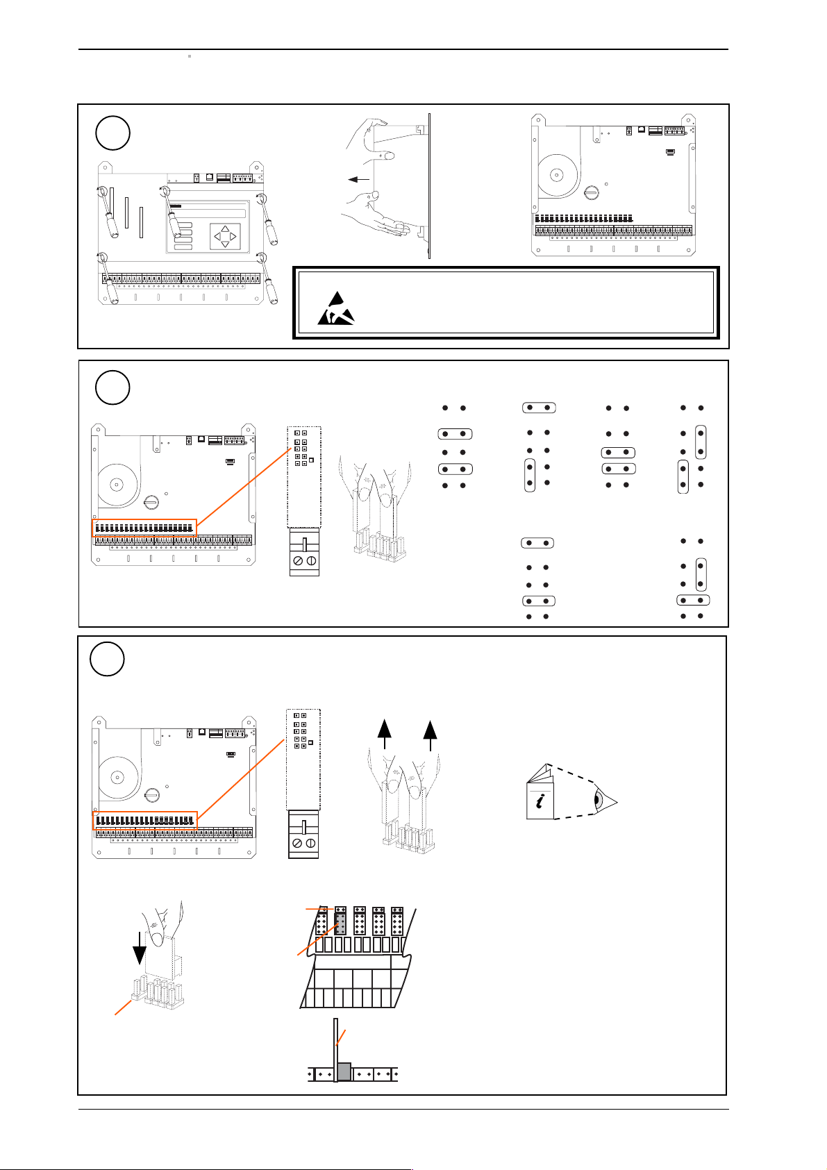
2 Installation - Configuration (continued)
Remove Cover
8
R X
BA U D
AD D RE SS
O K
1284163264
1K 2
9K 6
19K 2
TX
D P
A
B
C
D
9
10
CAUTION: This unit contains static sensitive devices. Suitable anti-static precautions
Link Input Channels
(unless link header being used on channel)
R X
BA U D
AD D RE SS
O K
19K 2
9K 6
1284163264
1K 2
TX
Fit Link Headers
(if used)
should be taken throughout this operation to prevent damage to the units.
BS EN100115/1 Basic Specification: protection of electrostatic sensitive
devices.
Thermistor
T
Digital loop
powered
D
Digital
externally powered
D x
Voltage
V
Current loop
powered
I
Current
externally powered
I x
(a) Identify set of pins
(d) Push on Link Header
2 pins free
BA U D
AD D RE SS
1284163264
1K 2
9K 6
19K 2
2 pins left free
link header in
position
(b) Remove links
R X
O K
TX
(c) Select Link Header
LKE/5V 5 V supply
LKE/15V 15 V supply
LKE/10mA 10 mA supply
IQ23x Data Sheet TA200538
A I 4
C
view on top of board
A I 4
A n A n + 1
A n - 1
C
C
C C C
A n + 2
board on left
hand side
view on front edge of board
2 - 2
IQ23x Series Controllers Installation Instructions TG200539 Issue 1/A 26/3/02
Page 7
Installation Instructions - Configuration IQ23x
R X
T X
O K
A
D
D P
C
B
1284163264
1K 2
9K 6
19 K2
AD D R ES S
BA U D
O
I
I Q 2 3 x
?
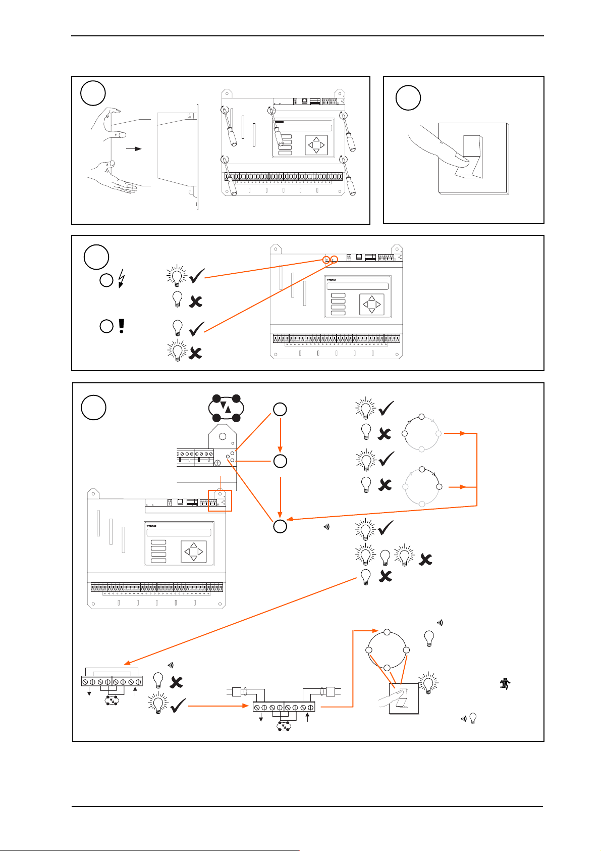
2 Installation - Configuration (continued)
11
13
a (power)
b (fail)
Replace Cover
Check Controller
(green)
(red)
Check supply
IQ Faulty
A
B
C
D
replace 5 screws
R X
BA U D
AD D RE S S
O K
1284163264
1K 2
9K 6
19K 2
TX
D P
12
Switch on
14
-
+
Check Network
A
B
C
D
OK
-
+
BA U D
AD D R ES S
1284163264
1K 2
9K 6
19 K2
D P
IQ Faulty
aRX
(yellow)
I Q 2 3 x
?
R X
O K
T X
bTX
(yellow)
R X
O K
T X
c OK
(green)
Network Address Invalid
0,2,3 or >119
OK
I Q 2 3 x
Check network cabling for
short circuits with a
multimeter (NOT Megger)
Check baud rate .
O
I
-
+
-
+
Power up other nodes
until faulty node is found
(OK ). Correct fault.
IQ23x Series Controllers Installation Instructions TG200539 Issue 1/A 26/3/02 2 - 3
Page 8
IQ23x Installation Instructions - Configuration
I Q 2 3 x
S
I Q 2 3 x
S
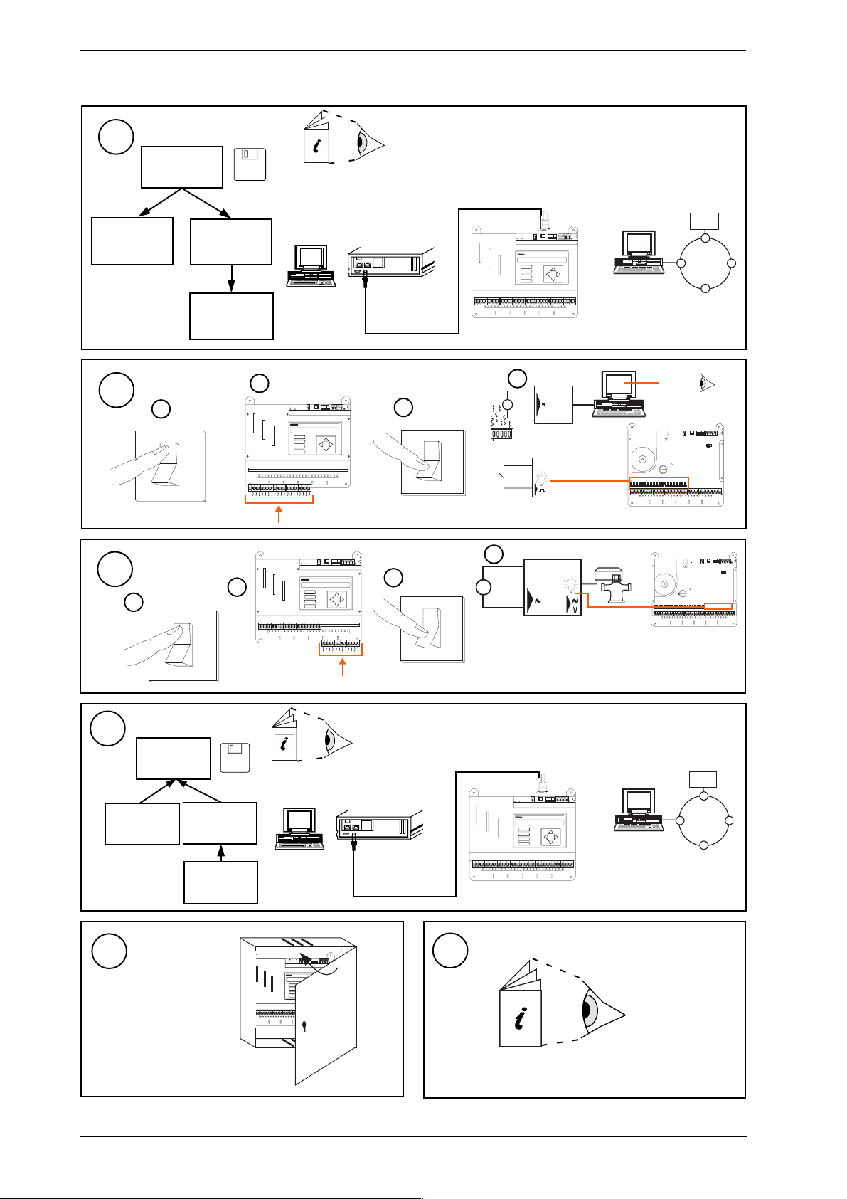
2 Installation - Configuration (continued)
15
IQ23x
also set time,
day, date
16
Configure
SET
if autodialled
X.IQ2
PowerTool
IQ23x
Test Inputs
Switch off
a
O
I
X.IQ2
IQ Configuration Manual 90-1533
IQ23x Data Sheet TA200538
SET Manual TE200147 or
PowerTool Manual TE200163
I Q 2 3 x
9 Way 'D type'
RX
BA UD
AD DRE SS
OK
1284163264
1K2
9K6
19K2
TX
D P
A
B
C
D
OR
Female
Cable/EJ101442
b
RX
BA UD
AD DRE SS
OK
1284163264
1K2
9K6
19K2
TX
D P
A
B
C
D
Switch on
c
O
I
IQ23x
d
I Q 2 3 x
(yellow)
∆T = X
RX
BAU D
ADD RE SS
OK
19K2
9K6
1284163264
1K2
TX
17
18
IQ23x
19
Test Outputs
Switch off
a
O
I
Backup
SET
(compare)
X.IQ2
PowerTool
Close Panel
b
if autodialled
X.IQ2
IQ23x
RX
BA UD
AD DRE SS
OK
1284163264
1K2
9K6
19K2
TX
D P
A
B
C
D
c
Switch on
O
d
e.g. VB
(yellow)
RX
BAU D
ADD RES S
OK
19K2
9K6
1284163264
1K2
TX
I
SET Manual TE200147
PowerTool Manual TE200163
I Q 2 3 x
9 Way 'D type'
RJ11
RX
BA UD
AD DRE SS
OK
1284163264
1K2
9K6
19K2
TX
D P
A
B
C
D
OR
Female
Cable/EJ101442
RX
AD DRE SS BAU D
OK
123 45 678 910
TX
SW 4
J1 6
DP
De v B
J1 5
A
B
C
De v A
D
20
IQ23x
3
IQ23x Installation Instructions Sheet 3: Options
2 - 4
IQ23x Series Controllers Installation Instructions TG200539 Issue 1/A 26/3/02
Page 9
Installation Instructions - Options
RX
TX
OK
A
D
D P
C
B
1284163264
1K2
9K6
19K2
AD DRE SS
BA UD
Series Controllers
SHEET 3: Installation Instructions - Options
3.1 Connecting a Remote 2-line Display (if KIT/2xx/RDS has been fitted)
IQ23x
Ensure /RDS
1
Installed
KIT/2xx/RDS
Installation Instructions
TG103128
DP
Connector
Connect Display
3
(FPK or HDP)
A UX
24 V
23 0V
RD S
RS 23 2/ MO DE M
R x
T+ T - R + R -
O K
T x
R +
T+
T-
R -
RX
BA UD
AD DRE SS
OK
1284163264
1K2
9K6
19K2
TX
Switch Off
2
O
I
3.2 Connecting to PC via Supervisor Port
Connect RS232
1
Switch On
4
O
1
Test
3
Adjust Viewing
Angle
6
5
angle adjust screw
Display Panel
Manual 90-1505
Configure Address
2
if faint
RJ11
RX
BA UD
AD DRE SS
OK
1284163264
1K2
9K6
19K2
TX
D P
9 F'D'
Cable/EJ101442
A
B
C
D
IQ23x
3.3 Connecting to NDP via Supervisor Port
1
Configure Address
See above 'Connecting to PC via
Supervisor port' Steps 1 & 2
Configuration Mode, addRess Module
sUpervisor port addr = 1,4 to 9, 11 to 119
sUpervisor port addr = 0
I Q 2 3 x
Cable/EJ104029
Connect NDP to Controller
2
9 Way
'D' Female
SET or
PowerTool
+
-
RJ11
IQ Configuration Manual 90-1533
IQ23x Data Sheet TA200538
sUpervisor port addr = 1,4 to 9, 11 to 119
sUpervisor port addr = 0
3
I Q 2 3 x
Test
IQ23x Series Controllers Installation Instructions TG200539 Issue 1/A 26/3/02 3 - 1
Page 10
IQ23x Installation Instructions - Options
123 456 789 10
RX
TX
OK
ADD RE SS B AUD
SW 4
A
D
DP
C
B
J1 6
De v B
J1 5
De v A
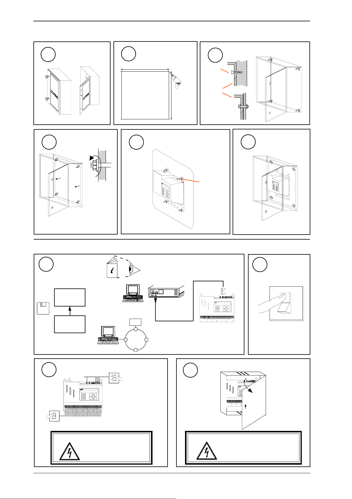
3.4 Mounting in an Enclosure, ENCLs/...
Open Door
1
a
b
2
Drill Wall
560 mm
3
No. 12
Fix to Wall
OR
560 mm
Remove Backplate
4
Mount IQ23x on Backplate
5
Replace Backplate
6
M6
3.5 Replacing the Battery
Upload Strategy
1
SET cannot upload
over autodial link
SET or
PowerTool
X.IQ2
IQ23x
Isolate I/O, Network
3
RX
BAU D
ADD RE SS
OK
1284163264
1K2
9K6
19K2
TX
D P
A
B
C
D
O
I
OR
SET Manual TE200147
PowerTool Manual TE200163
9 'D type'
Female
I Q 2 3 x
Cable/EJ101442
RJ11
BAU D
ADD RESS
1284163264
1K2
9K6
19K2
A
B
C
D
IQ23x
See above, "3.2
Connecting PC via
Supervisor Port"
Open Panel
4
Switch Off
2
RX
OK
TX
DP
O
I
WARNING: The connecting leads may be
3 - 2
connected to supplies. Isolate
before touching.
IQ23x Series Controllers Installation Instructions TG200539 Issue 1/A 26/3/02
WARNING: Opening the panel may expose
dangerous voltages.
417-IEC-5036
Page 11
Installation Instructions - Options IQ23x
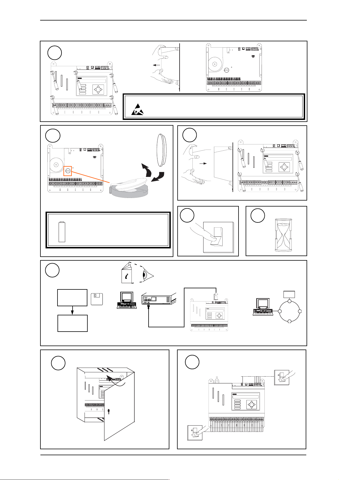
3.5 Replacing the Battery (continued)
RX
BA UD
AD DR ES S
OK
1284163264
1K2
9K6
19K 2
Remove Cover
TX
5
RX
BA UD
AD DR E SS
O K
1284163264
1K2
9K6
19K 2
TX
D P
A
B
C
D
CAUTION: This unit contains static sensitive devices. Suitable anti-static precautions
remove 5 screws
should be taken throughout this operation to prevent damage to the units.
BS EN100015/1 Basic Specification: protection of electrostatic sensitive devices.
Replace Battery
6
RX
BA UD
AD DR ES S
OK
19K 2
9K6
1284163264
1K2
TX
Warning: The lithium battery must not be recharged,
+
10
SET cannot download
over autodial link
Also set time, day, date.
disassembled, burnt or short circuited.
Misuse may cause explosion or fire.
Dispose of carefully. Refer to Health and
Safety Executive Guidance Note GS43.
Download Strategy
SET or
PowerTool
X.IQ2
IQ23x
Varta
CR2032
3V
7
8
SET Manual TE200147
PowerTool Manual TE200163
9 'D type'
Female
Cable/EJ101442
Replace Cover
Switch On
O
I
RJ11
RX
BAU D
ADD RES S
OK
1284163264
1K2
9K6
19K2
TX
D P
A
B
C
D
IQ23x
replace 5 screws
9
10s
OR
A
B
C
D
Wait
RX
BA UD
AD DR E SS
O K
1284163264
1K2
9K6
19K 2
TX
D P
I Q 2 3 x
11
Close Panel
12
RX
AD DR ES S B AU D
OK
12 34 567 89 10
TX
SW 4
J1 6
D P
D ev B
A
B
C
D
J1 5
D ev A
Reconnect Supply to I/O, Network
RX
BA UD
AD DR ES S
OK
1284163264
1K2
9K6
19K 2
TX
D P
A
B
C
D
IQ23x Series Controllers Installation Instructions TG200539 Issue 1/A 26/3/02 3 - 3
Page 12

IQ23x Installation Instructions - Options
RX
TX
OK
A
D
D P
C
B
1284163264
1K2
9K6
19K 2
AD DR ES S
BA UD
B A U D
A D D R E S S
12841 6
3 2
6 4
1 K 2
9 K 6
O
N
1 2 3 4 5 6 7 8 9 1 0
ç
1 9 K 2
12481 6
3 2
6 4
1 9 K 2
9 K 6
1 K 2
3.6 Zero Address/Baud Rate Switch Reset
Backup,
Switch Off,
1
Isolate,
Open Panel
Complete 'Replacing
the Battery' steps 1
to 4
Switch On
4
Note the Network Address
2
and Baud Rate
12481 6
3 2
6 4
A D D R E S S
1
284
1 6
3 2
6 4
e.g.
Address = 2 + 16 = 18
SET
NOT SET
5
O
I
1 9 K 2
9 K 6
1 K 2
B A U D
1 K 2
9 K 6
1 9 K 2
N
1 2 3 4 5 6 7 8 9 1 0
O
ç
Wait for Relays
1 9 K 2
9 K 6
1 K 2
1 9 K 2
9 K 6
1 K 2
1 9 K 2
9 K 6
1 K 2
9 K 6
1 K 2
1 9 K 2
BAU D
ADD RE SS
1284163264
1K2
9K6
19K2
D P
A
B
C
D
= 19k2 baud
= 9k6 baud
= 4k8 baud
= 1k2 baud
Set all Switch Poles
3
RX
OK
TX
to Zero
Address = 0 Baud = 0
'click'
BA UD
AD DRE SS
1284163264
1K2
9K6
19K2
A
B
C
D
NOT SET
RX
OK
TX
D P
Reset the Network Baud Rate
6
12481 6
19k2 baud
9k6 baud
4k8 baud
1k2 baud
A D D R E S S
12841 6
3 2
6 4
1 9 K 2
9 K 6
1 K 2
B A U D
3 2
6 4
1 K 2
9 K 6
1 9 K 2
N
1 2 3 4 5 6 7 8 9 1 0
O
ç
Baud Rate = B
9 K 6
1 K 2
1 9 K 2
1 9 K 2
9 K 6
1 K 2
= B
1 9 K 2
9 K 6
1 K 2
1 9 K 2
9 K 6
1 K 2
= B
= B
Reset the Network Address
7
RX
BA UD
AD DR ES S
OK
1284163264
1K2
9K6
19K 2
TX
D P
A
B
C
D
12481 6
3 2
6 4
1 9 K 2
9 K 6
1 K 2
e.g.
A D D R E S S
1
284
B A U D
1 6
3 2
6 4
1 K 2
9 K 6
1 9 K 2
N
1 2 3 4 5 6 7 8 9 1 0
O
ç
Address = A
= A
IQ23x
Address = 2 + 16 = 18
= A
/
SET
NOT SET
= A
/
= B
= A
/
address
Download Strategy,
1, 4 to 9, 11 to 119
Close Panel,
8
Reconnect Power to
0, 2 , 3,10 or >119
I/O
Complete 'Replacing the Battery'
steps 10 to 12
3 - 4
IQ23x Series Controllers Installation Instructions TG200539 Issue 1/A 26/3/02
Page 13

Installation Instructions - Replacing IQ111
Series Controllers
SHEET 4: Installation Instructions - Replacing IQ111
4 Replacing an IQ111 with an IQ231
Survey Unit
1
tcejbuSnoitseuQderiuqeRnoitcAtnempiuqElanoitiddA
gnixiF?desusrabgnixiferAselohgnixifwenllirdtsumONfI
?mm39nahtretaerghtpedlenapsI?deifidomebsihtnac,tonfI
O/I?desustuptuotnerrucerA ro(VMRShtiwIMRSecalperSEYfI
slennahcrehto
PD2lanretxElenapyalpsidenil2lanretxenasI
?dettif
PD2lanretnI?dettiflenapyalpsidenil2lanretnisI/PD/132QIesutsumSEYfInoitpo../PD/132QI
PDNlanetxE?detcennocPDNlanretxesI rof920401JE/ELBACelbacesuSEYfI
rosivrepuSlacoLrehtiedetcennocrosivrepuslacolsI
?emitotemitmorfroyltnenamrep
ylppuSyrailixuAslanimretylppusyrailixuaehterA
?desu
sredaeHkniL?desusredaehkniLerAwolebsredaehknilyfitnediSEYfI
?A/KLV5/EKLesUV5/EKL
?B/KLV51/EKLesUV51/EKL
?C/KLAm01/EKLesUAm01/EKL
?E/KLdetroppuston
?F/KLderiuqerton
?0/KLtnerrucderewopyllanretxerofkniL
)xI(rosnes
edoNlanretnI?dettifedonlanretninasIotdesuCNCsiedondnaSEYfI
wolebkcehc
draobNMTehtnodesabedonehtsI
ecnis,NMT,2CNI,2CNP,2CNC(
?)9991
,CNC(draobredlonaedonehtsI
,CNAdna,9991erofeb,CNI,CNP
,CNM,+CNX,82NX,CNE,DNA
?)CNIL
?2CNP,CNP,2CNC,CNCedonsI tekcosenilninip01100A971001JEesU
?ENMTedonsI tekcosenilninip01718301JEesU
?82NX,DNA,CNAedonsI tekcosenilninip011/3090-87esU
setaRduaB?2k1etarduabrosivrepussI 6k9otetarduabrosivrepusegnahC
rosneSlanretnIlanretninidesurosneslanretnisI
?edomlatigid
Note that KIT/IQ23x/UPGRADE also contains the 2 off 4 wide network extension cables (see step 15).
4
rewopdnalangis
244101JE/ELBACelbac
etalpdraobepytNMTesUnietalpdraobepytNMT
ecivedroretnirpottcennoc
medomottcennoc
medomottcennoc
1,605tibtesSEYfI
noDIV2esu,)slennahc2rofMRS2
SDR/xx2/TIKhtiw132QItiftsumSEYfISDR/xx2/TIK
wenhtiwelbacetelpmocecalperSEYfI
ylppusyrailixua132QIottcennocSEYfI
.elbacnoisnetxeyaw2ybslanimret
ytiraloppowsotrotcennoceriweR
otPDNrorosivrepuslacoltcennoc
,SEYfiesle,draobdracsid,krowten
etalpdraobepytNMT-erpesUnietalpdraobepytNMT-erp
otelbacDelamefyaw52ot)xeloM(
otelbacDelamyaw52ot)xeloM(
otelbacDelamyaw52ot)okcotS(
IQ23x
,IMRShcaerofeno(VMRS
)slennahc2rofMRS2ro
)slennahcowtrofeno(DIV2
920401JE/ELBAC
224101JE/ELBAC
nielbacnoisnetxeyaw2
EDARGPU/x32QI/TIK
x32QI/EDON/TIK
x32/EDON/TIK
ni100A971001JE
x32QI/EDON/TIK
ni718301JE
x32QI/EDON/TIK
ni1/3090/87
x32QI/EDON/TIK
IQ23x Series Controllers Installation Instructions TG200539 Issue 1/A 26/3/02 4 - 1
Page 14

IQ23x Installation Instructions - Replacing IQ111
I Q 1 1 1
A B
C D
A B
C D
I Q 1 1 1
4 Replacing an IQ111 with an IQ231 (continued)
Upload IQ111 Strategy
2
WupDn or
PowerTool
X.IQF
IQ111
9 'D type'
Female
Cable/58-0750
WupDn Manual TE200162
PowerTool Manual TE200163
Note Network Address
3
Use PowerTool, Lan 0, Address 0
Top Menu
tYpe Sensor difI/p Driver Functn loGic Loop scHedule
seQnc Analog digBit Knob sWitch Time Zone Oss
User addRess intcoN calarM reView Plot calEndar
R
Q
select addRess
module
to Quit module
IQ Configuration Manual 90-1533
Note Local address
to eXit configuration
X
mode
IQ111
25 Way 'D type'
Male
OR
I Q 1 1 1
Switch Off
4
O
I
Isolate I/O, Network
5
I Q 1 1 1
O
I
WARNING: The connecting
leads may be
connected to
supplies. Isolate
before touching.
Remove all Connections
8
I Q 1 1 1
6
I Q 1 1 1
Open Panel
Remove Cover
9
I Q 1 1 1
Check Connections
7
is external 2DP fitted?
Are auxiliary supply
connections used?
is local supervisor
connected?
is external NDP fitted?
is internal 2DP fitted?
is network connected?
4 - 2
IQ23x Series Controllers Installation Instructions TG200539 Issue 1/A 26/3/02
Page 15

Installation Instructions - Replacing IQ111 IQ23x
V
1
4 Replacing an IQ111 with an IQ231 (continued)
Check Setup
10
Note input link settings
V D T
1
Check for
Link Headers
If Node Fitted Remove Node Card
11
Note Baud Rate Settings
9 K 6
S u p e r v i s o r
1 K 2
1 9 K 2
9 K 6
N e t w o r k
4 K 8
1 K 2
Is a node fitted?
new (TMN type) board or not?
C
CNC, CNC2, PNC, PNC2
MNC, TMN
?
ANC, AND, XN28, XNC
Note that a CNC used to
Link Header type
LK/A, B, C, E, F, 0
Check output link settings
connect a local supervisor or
NDP to the network may be
discarded
Remove IQ111
12
Replace with IQ231
13
Same centres
If mounting bars were not used, redrill - see
Sheet 1 step 3
Connect Network
if used - see step 7 above
15
RX
BA UD
AD DR ESS
OK
1284163264
1K2
9K6
19K 2
TX
see Sheet 1 step 5
A
B
C
D
D P
2 off 4 wide network
extension cables
provided in
KIT/IQ23x/UPGRADE
screen
Connect Outputs
17
Channels previously linked as current (I) will need:
either (a) Replace SRMI by SRMV or (2SRM for pair of channels)
or (b) Add 2VID for each pair of channels
Otherwise signal leads should be plugged in channel for channel
- see Sheet 1 step 7
2VID Data Sheet TA101135A
SRMV Installation Instructions 91-2853
2SRM Installation Instructions TG103210
Connect Power
14
Plug in power lead - see
Sheet 1 step 4
R + R -T + T -
R + R -T + T -
-
-
+
+
-
+-+
Note: Early IQ111s had single part
input connectors so will require
terminals to be wired.
R +R -T +T - R +R -T +T -
Connect Auxiliary Supply
18
if used - see step 7 above
see Sheet 1 step 8
2 wide extension cable
provided in
KIT/IQ23x/UPGRADE
Rewire connector to swop polarity
Connect Inputs
16
Signal leads should plug
in channel for channel see Sheet 1 step 6
024
AD DR ES S
1284163264
A
B
C
D
0 24
RX
BA UD
OK
1K2
9K6
19K 2
TX
D P
24
0
IQ23x Series Controllers Installation Instructions TG200539 Issue 1/A 26/3/02 4 - 3
Page 16

IQ23x Installation Instructions - Replacing IQ111
123 4567 8910
RX
TX
OK
ADD RES S BAU D
SW 4
A
D
DP
C
B
J1 6
De v B
J1 5
De v A
4 Replacing an IQ111 with an IQ231 (continued)
Set Network Baud Rate to previous
19
as noted in step 10 above - see Sheet 2 step 6
Remove Cover
21
see Sheet 2 step 6
Fit Link Headers
23
to channels as noted in step 10 above
- see Sheet 2 step 10
Download Strategy file
previously saved in step 2 above
25
WupDn or
PowerTool
X.IQF
IQ231
set time, date, day of week
9 'D type'
Female
Cable/EJ101442
Set Network Address to previous
20
as noted in step 3 above - see Sheet 2 step 9
Link Input Channels
22
as noted in step 10 above - see Sheet 2 step 9
Replace Cover, Switch On,
24
Check Controller, Check Network
- see Sheet 2 steps 11 to 14
WupDn Manual TE200162
PowerTool Manual TE200163
RJ11
RX
BAU D
ADD RES S
OK
1284163264
1K2
9K6
19K2
A
B
C
D
IQ231
TX
DP
OR
I Q 2 3 1
Make IQ2xx Changes
either upload to SET and make changes,
26
or change in configuration mode - see Sheet 2 step 15 .
Loop Reschedule Time: Multiply by 5 and re-enter
Sensor Scaling Mode 1: If sensor outputs a voltage signal, and scaling mode 0, linear is being used, multipy T and B by 2 and re-enter.
Sensor Scaling Mode 2: If scaling mode 2 (linearise thermistor volts) is used, change it to sensor scaling mode 3 (linearise volts).
Shared Labels: Set up digital input labels. (Copy from sensor channel of same number if appropriate).
Internal Sensors: If an internal sensor is used in internal digital mode, bit 506,1 should be set to one
Test Inputs, Test Outputs, Backup
27
see Sheet 2 step 16 17 18
Connect Local Supervisor
29
if noted in step 7 - see Sheet 3 section 3.2
Set Baud Rate of Supervisor
if 1k2 supervisor baud rate noted in step 10 , and
31
supervisor connected in step 29 above, set baud rate
Connect External Display Panel
if noted in step 7 - see Sheet 3 section 3.1
28
Connect External NDP
30
if noted in step 7 - see Sheet 3 section 3.3
Close Panel
33
of supervisor to 9k6
Connect Internal Node
32
if noted in step 10 - see Sheets 8, 9
4 - 4
IQ23x Series Controllers Installation Instructions TG200539 Issue 1/A 26/3/02
Page 17

Installation Instructions - Replacing IQ111+
Series Controllers
SHEET 5: Installation Instructions - Replacing IQ111+
5 Replacing an IQ111+ with an IQ231
Survey Unit
1
tcejbuSnoitseuQderiuqeRnoitcAtnempiuqElanoitiddA
IQ23x
gnixiF08x083x083(xobllamsanidexiftisI
rewoPgniylppusfoelbapacylppussniamsI
?AV06
PD2lanretxE?dettiflenapyalpsidenil2lanretxenasI SDR/xx2/TIKhtiw132QItiftsumSEYfISDR/xx2/TIK
PD2lanretnI?dettiflenapyalpsidenil2lanretnisI/PD/132QIesutsumSEYfInoitpo../PD/132QI
PDNlanetxE?detcennocPDNlanretxesI rof920401JE/ELBACelbacesuSEYfI
rosivrepuSlacoLrehtiedetcennocrosivrepuslacolsI
ylppuSyrailixuA?desuslanimretylppusyrailixuaehterA ylppusyrailixua132QIottcennocSEYfI
sredaeHkniL?desusredaehknilerA wolebsredaehknilyfitnediSEYfI
V5/KLV5/EKLesUV5/EKL
V51/KLV51/EKLesUV51/EKL
Am01/KLAm01/EKLesUAm01/EKL
edoNlanretnI?dettifedonlanretninasI otdesuCNCsiedondnaSEYfI
?)CNIL,CNM,+CNX,82NX
?ENMTedonsI tekcosenilninip01718301JEesU
?82NX,DNA,CNAedonsI tekcosenilninip011/3090-87esU
rosneSlanretnIlatigidlanretninidesurosneslanretnisI
?edom
?sgnixiftuotucralucricimesgnisu)mm
?mm39nahtretaerghtpedlenapsI?deifidomebsihtnac,tonfI
?emitotemitmorfroyltnenamrep
draobNMTehtnodesabedonehtsI
?)9991ecnis,NMT,2CNI,2CNP,2CNC(
,CNP,CNC(draobredlonaedonehtsI
,CNE,DNA,CNAdna,9991erofeb,CNI
?2CNP,CNP,2CNC,CNCedonsI tekcosenilninip01100A971001JEesU
5
ylppusrewopesaercni,tonfI
rewopdnalangis
244101JE/ELBACelbac
wolebkcehc
etalpdraobepytNMTesUnietalpdraobepytNMT
ecivedroretnirpottcennoc
medomottcennoc
medomottcennoc
1,605tibtesSEYfI
selohgnixifwenllirdtsum,SEYfI
wenhtiwelbacetelpmocecalperSEYfI
elbacnoisnetxeyaw2ybslanimret
otPDNrorosivrepuslacoltcennoc
,SEYfiesle,draobdracsid,krowten
etalpdraobepytNMT-erpesUnietalpdraobepytNMT-erp
otelbacDelamefyaw52ot)xeloM(
otelbacDelamyaw52ot)xeloM(
otelbacDelamyaw52ot)okcotS(
920401JE/ELBAC
224101JE/ELBAC
nielbacnoisnetxeyaw2
EDARGPU/x32QI/TIK
x32QI/EDON/TIK
x32QI/EDON/TIK
ni100A971001JE
x32QI/EDON/TIK
ni718301JE
x32QI/EDON/TIK
ni1/3090/87
x32QI/EDON/TIK
IQ23x Series Controllers Installation Instructions TG200539 Issue 1/A 26/3/02 5 - 1
Page 18

IQ23x Installation Instructions - Replacing IQ111+
5 Replacing an IQ111+ with an IQ231 (continued)
Upload IQ111+ Strategy
2
WupDn or
PowerTool
X.IQF
IQ111+
Switch Off
3
O
I
WupDn Manual TE200162
PowerTool Manual TE200163
CABLE/78-1172
9 'D type'
Female
Cable/58-0750
IQ111+
Isolate I/O, Network
4
12 34 56 78 910
I Q 1 1 1 +
O
I
WARNING: The connecting leads may be
connected to supplies. Isolate
before touching.
O
I
25 way 'D type' Female
5 in line Stocko
Female
12 345 67 891 0
OR
I Q 1 1 1 +
5
I Q 1 1 1 +
Open Panel
12 34 567 89 10
I Q 1 1 1 +
Check Connections
6
is external 2DP fitted?
Remove Cover
8
is local supervisor connected?
is external NDP fitted?
A B
C D
1 23 4 5 6 7 89 1 0
is network connected?
is internal 2DP fitted?
A B
C D
I Q 1 1 1 +
Is auxiliary supply
connection used?
1 2 3 45 6 7 8 9 10
Remove all Connections
7
1 2 3 45 6 7 8 9 10
I Q 1 1 1 +
5 - 2
I Q 1 1 1 +
IQ23x Series Controllers Installation Instructions TG200539 Issue 1/A 26/3/02
Page 19

Installation Instructions - Replacing IQ111+ IQ23x
5 Replacing an IQ111+ with an IQ231 (continued)
Check Setup
9
Note input link settings
V DT
1
Check for
Link Headers
Link Header type
5V, 15V, 10mA
If Node Fitted Remove Node Card
10
Note address
Note baud rate settings
O N
1
284
1 6
3 2
6 4
1 K 2
1 2 3 4 5 6 7 8 9 10
9 K 6
1 9 K 2
B A U DA D D R E S S
e.g.
Address = 2 + 16 = 18
19k2 baud
SET
9k6 baud
1k2 baud
Is a node fitted?
new (TMN type) board or not?
1 5 V
CNC, CNC2, PNC, PNC2
MNC, TMN
ANC, AND, XN28, XNC
NOT SET
Note that a CNC used to
connect a local supervisor or
?
NDP to the network may be
discarded
Remove IQ111+
11
1 2 3 4 5 6 7 8 91 0
1 23 4 5 6 7 89 1 0
Replace with IQ231
12
Same centres
If mounted in small box (380 x 380 x 80 mm) using
semi-circular cutout fixings, redrill - see
Sheet 1 step 3
Connect Network
14
if used - see step 6 above
Network connections should plug in directly - see Sheet 1
step 5
Connect Outputs
16
Signal leads should be plugged in channel for channel - see
Sheet 1 step 7
Connect Power
13
Check mains supply can provide 60 VA.
Plug in power lead - see
Sheet 1 step 4
Connect Inputs
15
Signal leads should plug in channel for channel - see
Sheet 1 step 6
Connect Auxiliary Supply
17
if used - see step 6 above
24
0
BA UD
AD DR ES S
1284163264
19K 2
see Sheet 1 step 8
A
B
C
2 wide extension cable
provided in
KIT/IQ23x/UPGRADE
D
RX
OK
1K2
9K6
TX
D P
0
24
IQ23x Series Controllers Installation Instructions TG200539 Issue 1/A 26/3/02 5 - 3
Page 20

IQ23x Installation Instructions - Replacing IQ111+
123 4567 8910
RX
TX
OK
ADD RES S BA UD
SW 4
A
D
DP
C
B
J1 6
De v B
J1 5
De v A
5 Replacing an IQ111+ with an IQ231 (continued)
Set Node Baud Rate to previous
18
as noted in step 9 above - see Sheet 2 step 6
Remove Cover
20
see Sheet 2 step 6
Fit Link Headers
22
to channels as noted in step 9 above
- see Sheet 2 step 10
Download Strategy file
previously saved in step 2 above
24
WupDn or
PowerTool
X.IQF
IQ231
set time, date, day of week
9 'D type'
Female
Cable/EJ101442
Set Network Address to previous
19
as noted in step 9 above - see Sheet 2 step 9
Link Input Channels
21
as noted in step 9 above - see Sheet 2 step 9
Replace Cover, Switch On,
23
Check Controller, Check Network
- see Sheet 2 steps 11 to 14
WupDn Manual TE200162
PowerTool Manual TE200163
RJ11
RX
BAU D
ADD RES S
OK
1284163264
1K2
9K6
19K2
A
B
C
D
IQ231
TX
DP
OR
I Q 2 3 1
Make IQ2xx Changes
either upload to SET and make changes,
25
or change in configuration mode - see Sheet 2 step 15 .
Loop Reschedule Time: Multiply by 5 and re-enter
Sensor Scaling Mode 1: If sensor outputs a voltage signal, and scaling mode 0, linear is being used, multipy T and B by 2 and re-enter.
Sensor Scaling Mode 2: If scaling mode 2 (linearise thermistor volts) is used, change it to sensor scaling mode 3 (linearise volts).
Shared Labels: Set up digital input labels. (Copy from sensor channel of same number if appropriate).
Internal Sensors: If an internal sensor is used in internal digital mode, bit 506,1 should be set to one
Test Inputs, Test Outputs, Backup
26
see Sheet 2 step 16 17 18
Connect Local Supervisor
28
if noted in step 6 - see Sheet 3 section 3.2
Connect Internal Node
30
if noted in step 9 - see Sheets 8, 9
Connect External Display Panel
if noted in step 6 - see Sheet 3 section 3.1
27
Connect External NDP
29
if noted in step 6 - see Sheet 3 section 3.3
Close Panel
31
5 - 4
IQ23x Series Controllers Installation Instructions TG200539 Issue 1/A 26/3/02
Page 21

Installation Instructions - Replacing IQ131
Series Controllers
SHEET 6: Installation Instructions - Replacing IQ131
6 Replacing an IQ131 with an IQ233
Survey Unit
1
tcejbuSnoitseuQderiuqeRnoitcAtnempiuqElanoitiddA
gnixiF?desusrabgnixiferAselohgnixifwenllirdtsumONfI
IQ23x
?mm39nahtretaerghtpedlenapsI?deifidomebsihtnac,tonfI
O/I?desustuptuotnerrucerA rofMRS2ro(VMRShtiwIMRSecalperSEYfI
PD2lanretxE?dettiflenapyalpsidenil2lanretxenasI SDR/xx2/TIKhtiw332QItiftsumSEYfISDR/xx2/TIK
PD2lanretnI?dettiflenapyalpsidenil2lanretnisI/PD/332QIesutsumSEYfInoitpo../PD/332QI
PDNlanetxE?detcennocPDNlanretxesI langisrof920401JE/ELBACelbacesuSEYfI
rosivrepuSlacoLrehtiedetcennocrosivrepuslacolsI
?emitotemitmorfroyltnenamrep
ylppuSyrailixuA?desuslanimretylppusyrailixuaehterA ylppusyrailixua132QIottcennocSEYfI
sredaeHkniL?desusredaehkniLerA wolebsredaehknilyfitnediSEYfI
?A/KLV5/EKLesUV5/EKL
?B/KLV51/EKLesUV51/EKL
?C/KLAm01/EKLesUAm01/EKL
?D/KL)T(rotsimrehtrofkniL
?E/KLdetroppuston
?F/KLderiuqerton
?0/KL )xI(rosnestnerrucderewopyllanretxerofkniL
edoNlanretnI?dettifedonlanretninasI tcennocotdesuCNCsiedondnaSEYfI
draobNMTehtnodesabedonehtsI
?)9991ecnis,NMT,2CNI,2CNP,2CNC(
,CNP,CNC(draobredlonaedonehtsI
,CNE,DNA,CNAdna,9991erofeb,CNI
?)CNIL,CNM,+CNX,82NX
?2CNP,CNP,2CNC,CNCedonsI tekcosenilninip01100A971001JEesU
?ENMTedonsI ot)xeloM(tekcosenilninip01718301JEesU
?82NX,DNA,CNAedonsI )okcotS(tekcosenilninip011/3090-87esU
setaRduaB?2k1etarduabrosivrepussI 6k9otetarduabrosivrepusegnahC
6
slennahcrehtonoDIV2esu,)slennahc2
rewopdna
elbacwenhtiwelbacetelpmocecalperSEYfI
244101JE/ELBAC
elbacnoisnetxeyaw2otgniriwerybslanimret
,SEYfiesle,draobdracsid,krowtenot131QI
wolebkcehc
etalpdraobepytNMTesUnietalpdraobepytNMT
etalpdraobepytNMT-erpesU nietalpdraobepytNMT-erp
tcennocotelbacDelamefyaw52ot)xeloM(
ecivedroretnirpot
medomottcennocotelbacDelamyaw52
medomottcennocotelbacDelamyaw52ot
920401JE/ELBAC
224101JE/ELBAC
x32QI/EDON/TIK
x32QI/EDON/TIK
ni100A971001JE
x32QI/EDON/TIK
ni718301JE
x32QI/EDON/TIK
ni1/3090/87
x32QI/EDON/TIK
,IMRShcaerofeno(VMRS
)slennahc2rofMRS2ro
)slennahcowtrofeno(DIV2
nielbacnoisnetxeyaw2
EDARGPU/x32QI/TIK
rosneSlanretnIlatigidlanretninidesurosneslanretnisI
?edom
slatigiDlanretnIlennahctupniehtnilatigidlanretninasI
?desu02ot71egnar
Note that KIT/IQ23x/UPGRADE also contains the 2 off 2 wide network extension cables (see step 14).
IQ23x Series Controllers Installation Instructions TG200539 Issue 1/A 26/3/02 6 - 1
1,605tibtesSEYfI
lanretnignivomybygetartsegnahcSEYfI
noslatigidlanretnidesunufoaeraotlatigid
)sdrawno12tupnilatigid(332QI
Page 22

IQ23x Installation Instructions - Replacing IQ131
I Q 1 3 1
I Q 1 3 1
6 Replacing an IQ131 with an IQ233 (continued)
Upload IQ131 Strategy
2
WupDn or
PowerTool
X.IQF
IQ131
Switch Off
3
O
I
WupDn Manual TE200162
PowerTool Manual TE200163
9 'D type'
Female
Cable/58-0750
IQ131
Isolate I/O, Network
4
I Q 1 3 1
O
I
WARNING: The connecting leads may be connected
to supplies. Isolate before touching.
25 Way 'D type'
Male
OR
5
I Q 1 3 1
Open Panel
Check Connections
6
is external 2DP fitted?
I Q 1 3 1
Is auxiliary supply
connection used?
Remove Cover
8
I Q 1 3 1
Remove all Connections
is local supervisor
connected?
A B
C D
is external NDP fitted?
is internal 2DP fitted?
A B
C D
is network connected?
7
I Q 1 3 1
6 - 2
IQ23x Series Controllers Installation Instructions TG200539 Issue 1/A 26/3/02
Page 23

Installation Instructions - Replacing IQ131 IQ23x
V
1
O F F
1 2 3 4 5 6 7 8
D U M B
N O R M
12481 6
3 2
6 4
6 Replacing an IQ131 with an IQ233 (continued)
Check Setup
9
Note input link settings
V D
1
Check for
Link Headers
Link Header type
LK/A, B, C, D,
E, F, 0
If Node Fitted Remove Node Card
10
C
Check output link settings
1 2 3 4 5 6 7 8
OF F
12481 6
3 2
Note network baud rate
settings on integral CNC
D U M B
N O R M
6 4
1 9 K 2
Note supervisor
baud rate settings
BAUD
1k2 9k6
after removing node
1 2 3 4 5 6 7 8
O FF
12481 6
card step 10
D U M B
N O RM
6 4
3 2
Check network address on integral CNC
e.g Address = 2 + 16 = 18
Node
L
L
H
H
N
S
Supervisor
1
O F F
SET
1
O F F
NOT
SET
Is a node fitted?
new (TMN type) board or not?
CNC, CNC2, PNC, PNC2
MNC, TMN
?
ANC, AND, XN28, XNC
9 K 6
N e t w o r k
4 K 8
1 K 2
Note that a CNC used to connect a local supervisor or
NDP to the network may be discarded
Remove IQ111
11
Replace with IQ233
12
Same centres
If mounting bars were not used, redrill - see
Sheet 1 step 3
Connect Network
if used - see step 6 above
14
RX
BA UD
AD DR ESS
OK
1284163264
1K2
9K6
19K 2
TX
see Sheet 1 step 5
A
B
C
D
D P
2 off 2 wide network
extension cables
provided in
KIT/IQ23x/UPGRADE
screen
Connect Outputs
16
Channels previously linked as current (I) will need:
either (a) Replace SRMI by SRMV or (2SRM for pair of
channels)
or (b) Add 2VID for each pair of channels
Otherwise signal leads should be plugged in channel for
channel - see Sheet 1 step 7
2VID Data Sheet TA101135A
SRMV Installation Instructions 91-2853
2SRM Installation Instructions TG103210
Connect Power
13
Plug in power lead - see
Sheet 1 step 4
R + R - T + T -
R + R - T + T -
-
-
+
+
-
+-+
R +R -T +T -
Connect Auxiliary Supply
17
if used - see step 7 above
Note: Rewire +24 Vdc from
24 Vdc terminal on IQ131 into one
terminal of 2 way extension
connector and rewire 0 V from
adjacent 0 V terminal on IQ131 to
other terminal of 2 way extension
connector.
see Sheet 1 step 8
2 wide extension cable provided
in KIT/IQ23x/UPGRADE
Note: Early IQ131s had single part input
connectors so will require terminals to
be wired.
Connect Inputs
15
Signal leads should plug in
channel for channel - see
Sheet 1 step 6
24
0
A
B
C
D
0 24
RX
BA UD
AD DR ES S
OK
1284163264
1K2
9K6
19K 2
TX
D P
IQ23x Series Controllers Installation Instructions TG200539 Issue 1/A 26/3/02 6 - 3
Page 24

IQ23x Installation Instructions - Replacing IQ131
123 4567 8910
RX
TX
OK
ADD RES S BAU D
SW 4
A
D
DP
C
B
J1 6
De v B
J1 5
De v A
6 Replacing an IQ131 with an IQ233 (continued)
Set Network Baud Rate to previous
18
as noted in step 9 above - see Sheet 2 step 6
Remove Cover
20
see Sheet 2 step 6
Fit Link Headers
22
to channels as noted in step 9 above
- see Sheet 2 step 10
Download Strategy file
previously saved in step 2 above
24
WupDn or
PowerTool
X.IQF
IQ233
set time, date, day of week
9 'D type'
Female
Cable/EJ101442
Set Network Address to previous
19
as noted in step 9 above - see Sheet 2 step 9
Link Input Channels
21
as noted in step 9 above - see Sheet 2 step 9
Replace Cover, Switch On,
23
Check Controller, Check Network
- see Sheet 2 steps 11 to 14
WupDn Manual TE200162
PowerTool Manual TE200163
RJ11
RX
BAU D
ADD RES S
OK
1284163264
1K2
9K6
19K2
A
B
C
D
IQ233
TX
DP
OR
I Q 2 3 3
Make IQ2xx Changes
either upload to SET and make changes,
25
or change in configuration mode - see Sheet 2 step 15 .
Loop Reschedule Time: Multiply by 5 and re-enter
Sensor Scaling Mode 1: If sensor outputs a voltage signal, and scaling mode 0, linear is being used, multipy T and B by 2 and re-enter.
Sensor Scaling Mode 2: If scaling mode 2 (linearise thermistor volts) is used, change it to sensor scaling mode 3 (linearise volts).
Shared Labels: Set up digital input labels. (Copy from sensor channel of same number if appropriate).
Internal Sensors: If an internal sensor is used in internal digital mode, bit 506,1 should be set to one
Internal Digitals: If internal digitals in the range 17 to 20 are used, the strategy should changed bymoving them to
an area of unused internal digitals on IQ233 (digital input 21 onwards).
Test Inputs, Test Outputs, Backup
26
see Sheet 2 step 16 17 18
Connect Local Supervisor
28
if noted in step 6 - see Sheet 3 section 3.2
Connect External Display Panel
if noted in step 6 - see Sheet 3 section 3.1
27
Connect External NDP
29
if noted in step 6 - see Sheet 3 section 3.3
Set Baud Rate of Supervisor
if 1k2 supervisor baud rate noted in step 9 , and
30
supervisor connected in step 29 above, set baud rate
of supervisor to 9k6
Close Panel
32
Connect Internal Node
31
if noted in step 9 - see Sheets 8, 9
6 - 4
IQ23x Series Controllers Installation Instructions TG200539 Issue 1/A 26/3/02
Page 25

Installation Instructions - Replacing IQ131+
Series Controllers
SHEET 7: Installation Instructions - Replacing IQ131+
7 Replacing an IQ131+ with an IQ233
Survey Unit
1
tcejbuSnoitseuQderiuqeRnoitcAtnempiuqElanoitiddA
IQ23x
gnixiF08x083x083(xobllamsanidexiftisI
rewoPgniylppusfoelbapacylppussniamsI
?AV06
PD2lanretxE?dettiflenapyalpsidenil2lanretxenasI SDR/xx2/TIKhtiw332QItiftsumSEYfISDR/xx2/TIK
PD2lanretnI?dettiflenapyalpsidenil2lanretnisI/PD/332QIesutsumSEYfInoitpo../PD/332QI
PDNlanetxE?detcennocPDNlanretxesI rof920401JE/ELBACelbacesuSEYfI
rosivrepuSlacoLrehtiedetcennocrosivrepuslacolsI
ylppuSyrailixuA?desuslanimretylppusyrailixuaehterA ylppusyrailixua332QIottcennocSEYfI
sredaeHkniL?desusredaehknilerA wolebsredaehknilyfitnediSEYfI
V5/KLV5/EKLesUV5/EKL
V51/KLV51/EKLesUV51/EKL
Am01/KLAm01/EKLesUAm01/EKL
edoNlanretnI?dettifedonlanretninasI otdesuCNCsiedondnaSEYfI
?)CNIL,CNM,+CNX,82NX
?ENMTedonsI tekcosenilninip01718301JEesU
?82NX,DNA,CNAedonsI tekcosenilninip011/3090-87esU
rosneSlanretnIlatigidlanretninidesurosneslanretnisI
?edom
decneuqeStsaF
stupnIlatigiD
?emitotemitmorfroyltnenamrep
?desu02ot71egnarlennahc
?sgnixiftuotucralucricimesgnisu)mm
?mm39nahtretaerghtpedlenapsI?deifidomebsihtnac,tonfI
draobNMTehtnodesabedonehtsI
?)9991ecnis,NMT,2CNI,2CNP,2CNC(
,CNP,CNC(draobredlonaedonehtsI
,CNE,DNA,CNAdna,9991erofeb,CNI
?2CNP,CNP,2CNC,CNCedonsI tekcosenilninip01100A971001JEesU
tupninitupnilatigiddecneuqestsafasI
7
ylppusrewopesaercni,tonfI
rewopdnalangis
244101JE/ELBACelbac
wolebkcehc
etalpdraobepytNMTesUnietalpdraobepytNMT
ecivedroretnirpottcennoc
medomottcennoc
medomottcennoc
1,605tibtesSEYfI
4ot1slennahcotstupni
selohgnixifwenllirdtsum,SEYfI
wenhtiwelbacetelpmocecalperSEYfI
elbacnoisnetxeyaw2ybslanimret
otPDNrorosivrepuslacoltcennoc
,SEYfiesle,draobdracsid,krowten
etalpdraobepytNMT-erpesUnietalpdraobepytNMT-erp
otelbacDelamefyaw52ot)xeloM(
otelbacDelamyaw52ot)xeloM(
otelbacDelamyaw52ot)okcotS(
egnahcdnastupnieriwerSEYfI
latigiddecneuqestsafevomotygetarts
920401JE/ELBAC
224101JE/ELBAC
nielbacnoisnetxeyaw2
EDARGPU/x32QI/TIK
x32QI/EDON/TIK
x32QI/EDON/TIK
ni100A971001JE
x32QI/EDON/TIK
ni718301JE
x32QI/EDON/TIK
ni1/3090/87
x32QI/EDON/TIK
IQ23x Series Controllers Installation Instructions TG200539 Issue 1/A 26/3/02 7 - 1
Page 26

IQ23x Installation Instructions - Replacing IQ131+
7 Replacing an IQ131+ with an IQ233 (continued)
Upload IQ111+ Strategy
2
WupDn or
PowerTool
X.IQF
IQ131+
Switch Off
3
O
I
WupDn Manual TE200162
PowerTool Manual TE200163
CABLE/78-1172
9 'D type'
Female
Cable/58-0750
IQ131+
Isolate I/O, Network
4
12 34 56 78 910
I Q 1 3 1 +
O
I
WARNING: The connecting leads may be
connected to supplies. Isolate
before touching.
O
I
25 way 'D type' Female
5 in line Stocko
Female
12 345 67 891 0
OR
I Q 1 3 1 +
5
I Q 1 3 1 +
Open Panel
12 34 567 89 10
I Q 1 3 1 +
Check Connections
6
is external 2DP fitted?
Remove Cover
8
is local supervisor connected?
is external NDP fitted?
A B
C D
1 23 4 5 6 7 89 1 0
is network connected?
is internal 2DP fitted?
A B
C D
I Q 1 3 1 +
Is auxiliary supply
connection used?
1 2 3 45 6 7 8 9 10
Remove all Connections
7
1 23 4 5 6 7 89 1 0
I Q 1 3 1 +
7 - 2
I Q 1 3 1 +
IQ23x Series Controllers Installation Instructions TG200539 Issue 1/A 26/3/02
Page 27

Installation Instructions - Replacing IQ131+ IQ23x
7 Replacing an IQ131+ with an IQ233 (continued)
Check Setup
9
Note input link settings
V DT
1
Check for
Link Headers
Input channels
1 to 4 (T, I, V)
5 to 16 (T, I , V, D)
17 to 20 (D only, no links)
If Node Fitted Remove Node Card
10
Note address
Note baud rate settings
O N
1
284
1 6
3 2
6 4
1 K 2
1 2 3 4 5 6 7 8 9 10
9 K 6
1 9 K 2
B A U DA D D R E S S
e.g.
Address = 2 + 16 = 18
19k2 baud
SET
9k6 baud
1k2 baud
Is a node fitted?
new (TMN type) board or not?
1 5 V
Link Header type
5V, 15V, 10mA
CNC, CNC2, PNC, PNC2
MNC, TMN
ANC, AND, XN28, XNC
NOT SET
Note that a CNC used to
connect a local supervisor or
?
NDP to the network may be
discarded
Remove IQ131+
11
1 2 3 4 5 6 7 8 91 0
1 23 4 5 6 7 89 1 0
Replace with IQ231
12
Same centres
If mounted in small box (380 x 380 x 80 mm) using
semi-circular cutout fixings, redrill - see
Sheet 1 step 3
Connect Network
14
if used - see step 6 above
Network connections should plug in directly - see Sheet 1
step 5
Connect Outputs
16
Signal leads should be plugged in channel for channel - see
Sheet 1 step 7
Connect Power
13
Check mains supply can provide 60 VA.
Plug in power lead - see
Sheet 1 step 4
Connect Inputs
15
If fast sequenced digital inputs were connected
to IQ131+ input chaqnnels 17 to 20, they should
be rewired to input channels 1 to 4 and strategy modified
accordingly.
Otherwise signal leads should plug in channel for channel
- see Sheet 1 step 6
Connect Auxiliary Supply
17
if used - see step 6 above
24
0
BA UD
AD DR ES S
19K 2
9K6
1284163264
1K2
see Sheet 1 step 8
2 wide extension cable
provided in
KIT/IQ23x/UPGRADE
A
B
C
D
D P
RX
OK
TX
0
24
IQ23x Series Controllers Installation Instructions TG200539 Issue 1/A 26/3/02 7 - 3
Page 28

IQ23x Installation Instructions - Replacing IQ131+
123 4567 8910
RX
TX
OK
ADD RES S BAU D
SW 4
A
D
DP
C
B
J1 6
De v B
J1 5
De v A
7 Replacing an IQ131+ with an IQ233 (continued)
Set Node Baud Rate to previous
18
as noted in step 9 above - see Sheet 2 step 6
Remove Cover
20
see Sheet 2 step 6
Fit Link Headers
22
to channels as noted in step 9 above
- see Sheet 2 step 10
Download Strategy file
previously saved in step 2 above
24
WupDn or
PowerTool
X.IQF
IQ233
set time, date, day of week
9 'D type'
Female
Cable/EJ101442
Set Network Address to previous
19
as noted in step 9 above - see Sheet 2 step 9
Link Input Channels
21
as noted in step 9 above - see Sheet 2 step 9
Replace Cover, Switch On,
23
Check Controller, Check Network
- see Sheet 2 steps 11 to 14
WupDn Manual TE200162
PowerTool Manual TE200163
RJ11
RX
BAU D
ADD RES S
OK
1284163264
1K2
9K6
19K2
A
B
C
D
IQ233
TX
DP
OR
I Q 2 3 3
Make IQ2xx Changes
either upload to SET and make changes,
25
or change in configuration mode - see Sheet 2 step 15 .
Loop Reschedule Time: Multiply by 5 and re-enter
Sensor Scaling Mode 1: If sensor outputs a voltage signal, and scaling mode 0, linear is being used, multipy T and B by 2 and re-enter.
Sensor Scaling Mode 2: If scaling mode 2 (linearise thermistor volts) is used, change it to sensor scaling mode 3 (linearise volts).
Shared Labels: Set up digital input labels. (Copy from sensor channel of same number if appropriate).
Internal Sensors: If an internal sensor is used in internal digital mode, bit 506,1 should be set to one.
Fast Sequencing: If fast sequenced digital inputs in the input channel range 17 to 20 are used, they should be rewired
Test Inputs, Test Outputs, Backup
26
see Sheet 2 step 16 17 18
Connect Local Supervisor
28
if noted in step 6 - see Sheet 3 section 3.2
Connect Internal Node
30
if noted in step 9 - see Sheets 8, 9
and the strategy modified to move them to input channels 1 to 4.
Connect External Display Panel
if noted in step 6 - see Sheet 3 section 3.1
27
Connect External NDP
29
if noted in step 6 - see Sheet 3 section 3.3
Close Panel
31
7 - 4
IQ23x Series Controllers Installation Instructions TG200539 Issue 1/A 26/3/02
Page 29

Installation Instructions - Node Part 1
IQ23x
Series Controllers
SHEET 8: Installation Instructions - Node Part 1
8 Installing an auxiliary internal node board from a replaced controller - part 1
KIT/NODE/IQ23x
1
All the parts required to install
a node into the IQ23x are
included in KIT/NODE/IQ23x.
Switch Off
4
O
I
Remove Cover
7
BA UD
AD DR E SS
1284163264
1K2
9K6
19K 2
A
B
C
D
IQ131 internal
CNC board
2
The IQ131 auxiliary internal CNC
node board is replaced by the
IQ233 firmware node, so the CNC
board can be discarded.
Isolate I/O
5
A
B
C
D
O
I
WARNING: The connecting leads
may be connected to
supplies. Isolate before
touching.
RX
BAU D
ADD RES S
OK
1284163264
1K2
9K6
19K2
TX
D P
8
RX
O K
TX
D P
IQ1xx Supervisor CNC board
3
If an auxiliary internal CNC board was fitted to allow
a local supervisor or NDP to communicate over the
network, this can now be achieved by setting the local
supervisor port address in the range 1, 4 to 119 (excluding
address 10, see Sheet 3, Section 3.2) and the CNC board
can be discarded.
8
Open Panel
6
WARNING: Opening the panel
may expose
dangerous voltages.
417-IEC-5036
Remove Network Links
J47
pull off links
J48
J47
J48
RX
BA UD
AD DR ES S
OK
1284163264
1K2
9K6
19K 2
TX
RX
ADD RESS BAU D
OK
123 4567 8910
TX
SW 4
J1 6
DP
De v B
J1 5
A
B
C
De v A
D
remove 5 screws
RX
BA UD
AD DR ES S
OK
19K 2
9K6
1284163264
1K2
TX
CAUTION: This unit contains static sensitive devices.
Suitable anti-static precautions should be
taken throughout this operation to prevent
damage to the unit.
BS EN100115/1 Basic Specification: protection of
electrostatic sensitive devices.
IQ23x Series Controllers Installation Instructions TG200539 Issue 1/A 26/3/02 8 - 1
9
Not ANC, AND, MNC, TMN if on internetwork.
Not INC2 if used as internetwork repeater (dumb/normal =
normal, address >= 100).
AD DR ES S
1284163264
Install Support Pillar
10
BA UD
AD DRE SS
1284163264
1K2
9K6
19K2
RX
BA UD
OK
19K 2
9K6
1K2
TX
CABLE/EJ103086
polarized
connector
J47
J48
Select Board Plate
If the node board is of
11
RX
OK
TX
PNC2, INC2, TMN) then select
the TMN type board plate, else
(CNC, PNC. INC, ANC, AND,
ENC, XN28, XNC+, MNC,
LINC) select the pre-TMN type
board plate.
TMN type (CNC2,
Connect Local Network Cable
Page 30

IQ23x Installation Instructions - Node Part 1
~
0 V
~
8 Installing an auxiliary internal node board from a replaced controller - part 1 (continued)
Screw on Plate
12
3 screws provided
Fix Node to Plate
14
4 screws provided
Place Node on Plate
13
Ensure correct orientation of node board
RX
BA UD
AD DR ES S
OK
1284163264
1K2
9K6
19K 2
TX
Pre-TMN type boards
J 1
P O W E R
J 2
R S 2 32 A
J 5
power connector top left
hand corner
Connect Earth Cable
15
to IQ23x
R X
BA UD
AD D RE SS
O K
1284163264
1K2
9K6
19K 2
TX
EJ101835
16
Pre-TMN type boards
J1
P O W E R
EJ101835
TMN type boards
J 7
D e v A
J 15
M o d em
D e v B
J 16
E T 1
L an B L a n A
J 9J 8
power connector top right
hand corner
Connect Earth to Node Board
TMN type boards
L an B L a n A
J7
J9J8
D ev A
J1 5
M o de m
D ev B
J2
R S 23 2 A
J5
J1 6
E T1
Connect Power Cable to Node Board
17
CABLE/EJ103087
POWER
Pre-TMN type boards
J 1
P O W E R
~
~O+
-
J 2
R S 2 3 2 A
D e v A
M o d e m
D e v B
J 5
TMN type boards
L a n B L an A
J 7
J 9J8
J 15
J 16
E T 1
CABLE/EJ103087
Ensure socket is connected to correct terminal pins (+, -, or , 0V)
Connect Local Network to Node Board (4 wide)
19
Note: ANC, AND, MNC, TMN if on internetwork
Note: INC2 if used as internetwork repeater (dumb/normal = normal,
address >=100). For LINC see step 21
CABLE/EJ103086
T T +
Lan A
R -
R +
INC, ANC, ENC, XN28,
XNC+ (circa 1988)
CNC, PNC (circa 1988)
CNC, PNC (circa 1997)
J2
Connect Power
18
Cable to IQ23x
CABLE/EJ103087
polarized connector
J2
1
SWITCH ON
DO NOT
O
INC, ANC, AND, ENC,
XN28 (circa 1997)
RX
BA UD
AD DR ES S
OK
1284163264
1K2
9K6
19K 2
TX
P O W E R
J 1
P O W E R
J 2
J 1
P O W E R
(ENC only)
J 2
R S 2 3 2 A
J 5
local network (J5)
8 - 2
J 3
L A N
local network (LAN)
IQ23x Series Controllers Installation Instructions TG200539 Issue 1/A 26/3/02
J 7
J 2
R S 2 3 2 A R S 23 2 B
L a n BL a n A
J 4
J 5
J 3
local network (Lan A) local network (Lan A)
P O W E R
J 2
(ENC only)
J 3
J 4
J 1 3
J 1 2
R S2 3 2 A
R S2 3 2 B
L a n BL a n A
Page 31

Installation Instructions - Node Part 1 IQ23x
J 7
E T 1
J 1 6
D e v B
J 1 5
D e v A
J 9J 8
L a n B L a n A
M o d e m
8 Installing an auxiliary internal node board from a replaced controller - part 1 (continued)
Connect Local Network to Node Board (4 wide) (continued)
20
local network (Lan)
Connect Local Network to Node Board (8 wide)
21
For LINC only (if not used as internetwork Lan extension node (address >=100))
J 1
P O W E R
MNC (circa 1989)
P O W E R
J 1
J 4
L a n
1 0
9
local network (Lan A)
(a) Rewire cable EJ103086 (b) Connect cable
CABLE/EJ103086
TT+
RR+
CNC2, PNC2, INC2, TMN (circa 1999)
L a n B L a n A
J 7
J 9J 8
D e v A
J 1 5
M o d e m
D e v B
J 1 6
E T 1
Remove
4 way
T - R - R +T + T - R - R +T +
Integral modem
(TMNH only)
plug
S C N
S C N
J 1 5
J 1 1
J 1 2
Connect Internetwork and Internetwork Segment A to Node Board
22
For ANC, AND, XN28, MNC, or LINC on internetwork (for LINC connection see next page, step 22d)
For INC2 if used as internetwork repeater (dumb/normal = normal, address >=100)
(a)
(c) connect 4 wide
internetwork cable
ANC, XN28 (circa 1986)
J 1
P O W E R
L A N
J 9 J 17
CABLE/EJ103086
local network
R X
BA UD
AD DR E SS
O K
1284163264
1K2
9K6
19K 2
TX
ANC, AND, XN28 (circa 1997)
P O W E R
J 2
TT+
RR+
Wire
2 x 2 way
plugs
Ensure sockets are connected to correct terminal pins
(b)
T T +
Lan A
R -
R +
MNC INC2, TMN
P O W E R
J 1
CABLE/EJ103086
R X
BA U D
AD D RE SS
O K
1284163264
1K 2
9K 6
19K 2
TX
J 3
J 4
J 1 3
R S 2 3 2 A R S 2 3 2 B
Internetwork (Lan A)
IQ23x Series Controllers Installation Instructions TG200539 Issue 1/A 26/3/02 8 - 3
L a n BL a n A
Internetwork (Lan A)
J 4
J 5
J 3
J 2
J 1 2
R S2 3 2 A
R S2 3 2 B
L a n BL a n A
J 4
L a n
Internetwork (Lan)
(Lan A)
Internetwork Segment A (INC2)
Internetwork (TMN)
Page 32

IQ23x Installation Instructions - Node Part 1
T -
R -
R +
T +
T -
R -
R +
T +
8 Installing an auxiliary internal node board from a replaced controller - part 1 (continued)
Connect Internetwork and Internetwork Segment A to Node Board (continued)
22
(d) connect 8 wide
LINC
J 1
P O W E R
10
9
L A N
J 9 J 1 7
J 1 5
J 1 1
Connect Internetwork and Internetwork Segment B to Node Board
23
Internetwork for INC, INC2
Internetwork Segment B for INC2 if used as internetwork repeater (dumb/normal = normal, address >=100)
J 1 2
Internetwork
internetwork cable
(a)
(d) Insert Gland into Box
(e) Connect internetwork
internetwork cable
R X
BA U D
AD D RE S S
O K
1284163264
1K 2
9K 6
19K 2
TX
(b) Place Cable in Gland
(c) Close Gland
strain relief
gland
(supplied)
R X
BA U D
AD D RE S S
O K
1284163264
1K 2
9K 6
19K 2
TX
T T +
Lan B
R -
R +
INC (circa 1988)
J 1
P O W E R
INC (circa 1997)
P O W E R
J 2
(Lan B)
Internetwork
Internetwork Segment B if
J 3
J 2
R S 2 3 2 A R S 2 3 2 B
Internetwork
(Lan B)
J 3
J 4
J 1 3
J 4
J 5
L a n BL a n A
J 1 2
R S2 3 2 A
R S2 3 2 B
L a n BL a n A
Internetwork
(Lan B)
INC2 used as
internetwork repeater
INC2 (circa 1999)
L a n B L a n A
J 7
J 9J 8
D e v A
J 1 5
M o d e m
D e v B
J 1 6
E T 1
Internetwork
8 - 4
IQ23x Series Controllers Installation Instructions TG200539 Issue 1/A 26/3/02
Page 33

Installation Instructions - Node Part 2
IQ23x
Series Controllers
SHEET 9: Installation Instructions - Node Part 2
9 Installing an auxiliary internal node board from a replaced controller - part 2
Connect RS232 to Node Board
24
for CNC, PNC, ANC, XNC+, XN28, AND, CNC2, PNC2, TMNE
(a) Knock out RS232/modem hole
RX
BA UD
AD DR E SS
O K
1284163264
1K2
9K6
19K 2
TX
(b) Fit appropriate cable's connector to hole
BA UD
AD DR E SS
O K
1284163264
1K2
9K6
19K 2
25 Way D
9
type
R X
TX
for CNC, CNC2, PNC,
PNC2, cable EJ100179A001
for TMNE, cable EJ103817
for ANC, AND, XN28,
cable EJ100022A003
(c) Connect RS232 to board
CNC, PNC (circa 1988)
J 1
P O W E R
J 2
R S 2 3 2 A
J 5
RS232
25 Way D type
female
1
ANC, XN28 (circa 1988)
J 1
P O W E R
J 4
J 5
J 3
J 2
R S 2 3 2 A R S 2 3 2 B
L a n BL a n A
RS232 (RS232 B)
CNC, PNC (circa 1997)
P O W E R
J 2
J 3
L A N
J 7
RS232
black sheath
CABLE/EJ100179A001
10 Way Molex Socket
(pins 2-4, 3-5 linked)
check polarity
ANC, AND, XN28 (circa 1997)
P O W E R
J 2
J 3
J 4
J 1 3
J 1 2
R S2 3 2 A
R S2 3 2 B
L a n BL a n A
RS232 (RS232 B)
CABLE/78-0903/1
RS232
(Dev B Modem)
25 Way D type
female
RS232
(Dev B Modem)
CNC2, PNC2 (circa 1999)
L a n B L a n A
J 7
J 9J 8
D e v A
J 1 5
M o d e m
D e v B
J 1 6
E T 1
black sheath
CABLE/EJ100179A001
10 Way Molex Socket
(pins 2-4, 3-5 linked)
polarized
1
TMNE (circa 1999)
L a n B L a n A
J 7
J 9J 8
D e v A
J 1 5
M o d e m
D e v B
J 1 6
E T 1
red sheath
CABLE/EJ103817
10 Way Molex Socket
polarized
25 Way D type
male
10 Way Stocko Socket
(pins 2-4 linked)
25 Way D type
male
check polarity
1
1
IQ23x Series Controllers Installation Instructions TG200539 Issue 1/A 26/3/02 9 - 1
Page 34

IQ23x Installation Instructions - Node Part 2
J 7
E T 1
J 1 6
D e v B
J 1 5
D e v A
J 9J 8
L a n B L a n A
M o d e m
E
9 Installing an auxiliary internal node board from a replaced controller - part 2 (continued)
Connect Device to IQ23x RS232/Modem Connector
25
CNC, CNC2
9 Way D type Female
CABLE/58-0750
25 Way D type Male
Route Special Device Cables
26
For ENC, MNC, TMNH
(b) Identify cable
ENC (circa 1988) TMNH
ENC (circa 1997)
PNC, PNC2
25 Way D type Male
special cable, pins 3,7,20
connected straight through
25 Way D type Male
ANC, AND, XN28, TMNE
Modem/
Terminal
Adaptor
AD D R
128
4
(a) Remove TMNH adaptor plug
for TMNH only
MNC
25 Way D type Male
CABLE/58-2894
25 Way D type Female
J 1
P O W E R
fibre optic to TTL adaptor
R S 2 3 2 A R S 2 3 2 B
L a n BL a n A
J 4
J 5
J 3
J 2
(c) Knock out hole
BA UD
AD DR E SS
1284163264
19K 2
(f) Insert Gland into Box
BA UD
AD DR ES S
1284163264
9K6
19K 2
P O W E R
J 2
RX
O K
1K2
9K6
TX
RX
O K
1K2
TX
fibre optic to TTL adaptor
J 3
J 4
J 1 3
J 1 2
R S2 3 2 A
R S2 3 2 B
L a n BL a n A
(d) Place Cable in Gland
(g) Replace TMNH adaptor plug
for TMNH only
P O W E R
J 1
Integral modem
(TMNH only)
J 4
L a n
(e) Close Gland
strain relief
gland (supplied)
(h) Connect to device
ENC
EMMPO
MNC, TMNH
PSTN
27
Link Network Connectors
RX
BA UD
AD DR ES S
OK
1284163264
1K2
9K6
19K 2
TX
If ANC, AND, XN28, MNC, TMN, is fitted
and IQ23x is not networked (stand alone)
links
T -T +R -R + T -T +R -R +
-+-+ -+-+
9 - 2
IQ23x Series Controllers Installation Instructions TG200539 Issue 1/A 26/3/02
Page 35

Installation Instructions - Node Part 2 IQ23x
O
1
J 7
E T 1
J 1 6
D e v B
J 1 5
D e v A
J 9J 8
L a n B L a n A
M o d e m
I Q 2 3 x
?
J 7
E T 1
J 1 6
D e v B
J 1 5
D e v A
J 9J 8
L a n B L a n A
M o d e m
9 Installing an auxiliary internal node board from a replaced controller - part 2 (continued)
Connect to LonWorks
28
For LINC only
(c) Connect Lon cables(b) Push cables through hole
(a) Knock out hole
R X
BA U D
AD D RE S S
O K
1284163264
1K 2
9K 6
19K 2
TX
Check Settings
29
if appropriate
Node
Controller Data
Sheet
(a) Check network baud rate.
(b) Check network address and bumb/normal switch.
(c) Check 2nd network/device baud rate.
Check Node Controller
31
Switch On
30
a PWR ON
SCN
(green)
LanA
SCN
LanB
LanA
LanB
J 1
P O W E R
J 1 5
J 1 1
10
9
L A N
J 9 J 1 7
J 1 2
Check supply
b W/DOG
TMN type board shown
Check data sheet for
location of LEDs on other
(red)
Node Faulty
boards
Check Trend Lan and Internetwork sections
32
TMN type board
shown
Check data sheet
for location of
LEDs on other
boards
T X - T X + R X - R X +
IQ23x Series Controllers Installation Instructions TG200539 Issue 1/A 26/3/02 9 - 3
Do separate check fo each Lan/Internetwork segment
LAN
OK
Node Faulty
LAN
T X - T X + R X - R X +
aRX
(yellow)
bTX
(yellow)
c OK
(green)
node
node
node
I Q 2 3 x
?
Network Address Invalid
0, 2, 3 or >119
OK
Check baud rate . Check
network cabling for short circuits
with a multimeter (NOT Megger)
O
I
Power up other nodes until
faulty node is found
(OK ). Correct fault.
Page 36

IQ23x Installation Instructions - Node Part 2
12 345 67 891 0
RX
TX
OK
AD DRE SS BA UD
SW 4
A
D
D P
C
B
J1 6
De v B
J1 5
De v A
9 Installing an auxiliary internal node board from a replaced controller - part 2 (continued)
Replace Cover
33
Reconnect Supply to I/O
35
R X
BA U D
AD D RE S S
O K
1284163264
1K 2
9K 6
19K 2
TX
D P
A
B
C
D
34
replace 5 screws
Configure
36
Close Panel
RX
BA UD
AD DR ES S
OK
1284163264
1K2
9K6
19K 2
TX
D P
A
B
C
D
(INC, INC2, ANC, AND,
XN28, MNC, TMN, ENC,
XNC+, LINC)
if required
Node Installation Instructions
37
Test System
Node Installation Instructions
Trend Control Systems Ltd reserves the right to revise this publication from time to time and make changes to the content
hereof without obligation to notify any person of such revisions or changes.
Trend Control Systems Ltd. P.O. Box 34 Horsham Sussex RH12 2YF Tel:+44 (0)1403 211888 Fax:+44 (0)1403 241608 www.trend-controls.com
9 - 4
IQ23x Series Controllers Installation Instructions TG200539 Issue 1/A 26/3/02
 Loading...