

Page 1
Important: Retain these instructions
TX R X
LAN
LAN
1
2 3 4 5
6 7 8
9 101112
13
14
15
V
24V
16
17
18
19
20
TX RX
LAN
LAN
1
2 3 4 5
6 7 8
9 101112
13
14
15
V
24V
16
17
18
19
20
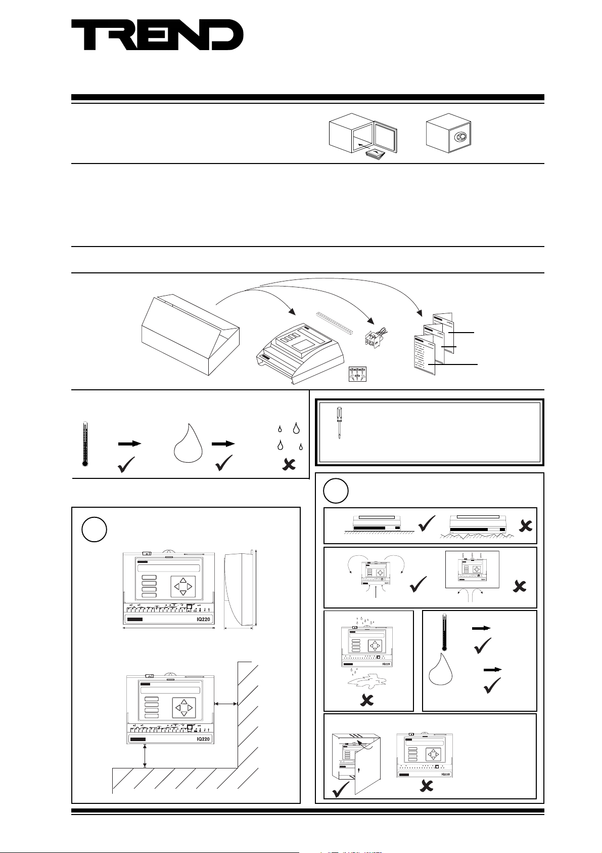
Installation Instructions - Mounting
IQ22x
Series Controllers
CONTENTS
1.1 Unpacking 1 - 1
1.2 Storing 1 - 1
1.3 Installation - Mounting 1 - 1
2.1 Installation - Configuration 2 - 1
2.2 Disposal 2 - 4
3.1 Fitting a Remote 2-line Display 3 - 1
3.2 Connecting to a PC using Supervisor Port 3 - 1
3.3 Connecting to an NDP using Supervisor Port 3 - 1
3.4 Mounting in an Enclosure,ENCLS/... 3 - 2
3.5 Replacing the Battery 3 - 2
3.6 Zero Address/Baud Rate Switch Reset 3 - 4
SHEET 1: Installation Instructions - Mounting
1.1 Unpacking
1.2 Storing
-10 °C
(14 °F)
+50 °C
(122 °F)
0
H2O
90 %RH
1
IQ22x Installation Instructions
TG200001
Sheet 1: Mounting
(24 V
version
only)
It is recommended that the installation should
comply with the HSE Memorandum of Guidance
on Electricity at Work Regulations 1989.
For USA install equipment in accordance with
National Electric Code.
Sheet 2: Configuration
Sheet 3: Options
1.3 Installation - Mounting
1
Dimensions
A
B
C
D
1 6
1
2 3 4 5
1
2 3 4 5
1 1
6 7 8
9 1 0
230 mm (9.05")
A
B
C
D
6 7 8
9 1 0
100 mm (3.94")
D P
L A N
1 7
2 0
1 8
1 9
L A N
T X R X
V
2 4 V
1 2
1 3
1 5
1 4
D P
L A N
1 7
2 0
1 8
1 6
1 9
L A N
T X R X
V
2 4 V
1 1
1 2
1 3
1 5
1 4
70 mm
(2.75")
50 mm
(1.97")
181 mm (7.125")
2
Requirements
a
b
c
LA N
17
20
18
16
19
LA N
TX R X
V
1
2 3 4 5
24 V
6 7 8
9 101112
13
15
14
e IQ22x/USA only
1
2 3 4 5
17
20
18
16
19
V
24V
1
6 7 8
9 101112
2 3 4 5
13
15
14
d
0 °C
(32
°F)
0 %RH
H2O
Protection IP30, NEMA 2
The unit is UL rate
as 'UL916, listed
open energy
management
LA N
17
20
18
16
19
LA N
TX RX
V
24 V
6 7 8
9 1 01112
13
15
14
equipment'
LAN
LAN
TX RX
+45 °C
(113 °F)
90 %RH
IQ22x Series Contollers Installation Instructions TG200001 Issue 1/G 08/05/06
1 - 1
Page 2
IQ22x Installation Instructions - Mounting
T X R X
L AN
L AN
1
2 3 4 5
6 7 8
9 10
1 1
1 2
1 3
1 4
1 5
V
2 4V
1 6
1 7
1 8
1 9
2 0
( g
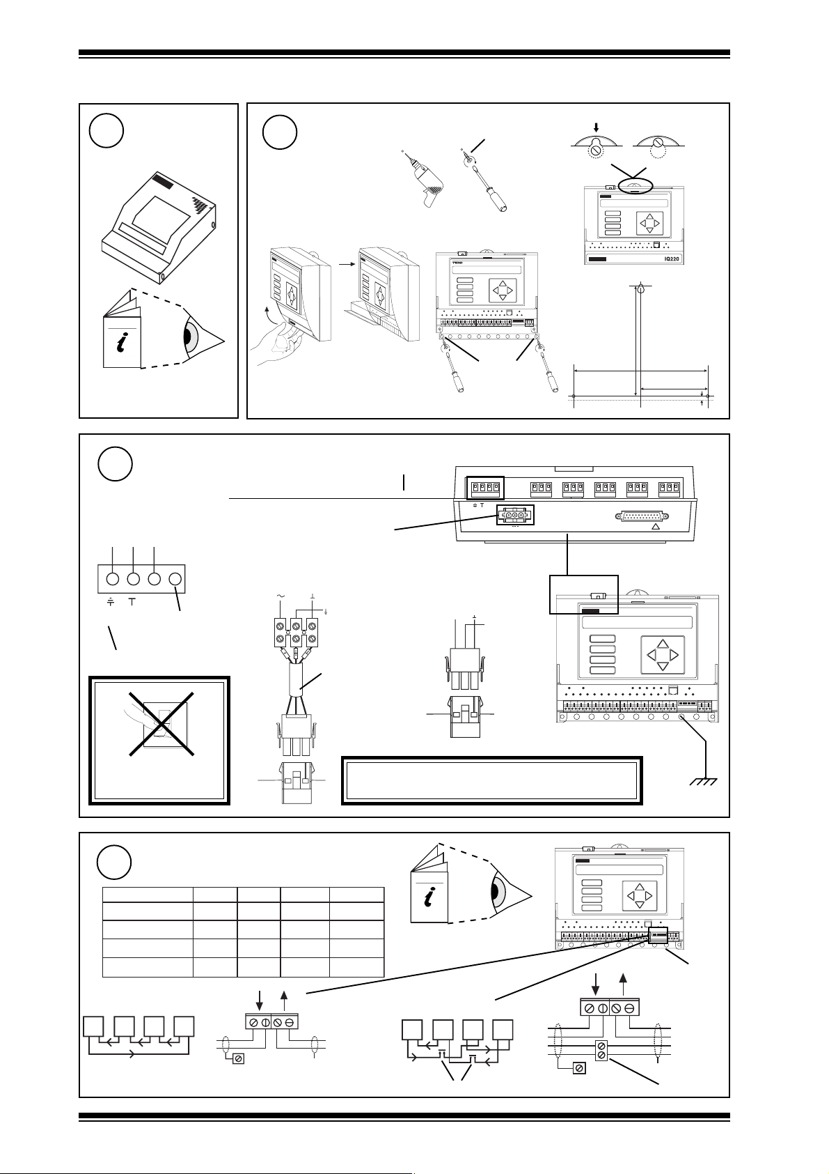
1.3 Installation - Mounting (continued)
Mount MBOX
3
if using
4
ENCLS/MBOX/IQ22x
e
ENCLS/MBOX/IQ22x
Installation Instructions
TG200203
5
Connecting Power
IQ22x Consumption > 13 VA
230 Vac version
Terminal size 0.5 to 2.5 mm2 (14 to 20 AWG)
E N L
2 part Mat-N-Loc connector
Mounting
24 V version
b
Ø 6 mm
ca
b
(0.24")
f
A
B
C
D
12 3 45 67 8 910
(6.77")
172 mm
M O D E M
209 mm (8.23")
104.5 mm (4.11")
7 mm (0.28")
R D S / R S 2 3 2
!
Ø 6 mm
(0.24")
2 3 0 V
~
2 4 V
N C N O C N C N O C N C N O C N C N O C N C N O C
~
+ 2 4 V 0 V
2 4 V d c :
2 4 V a c
2 4 V a c :
~
E N L
Earth (ground)
DO NOT APPLY
6
2 wire
T R T R T R T R
Terminal size 0.5 to 2.5 mm2 (14 to 20 AWG)
no
connection
O
1
POWER
Connect Network
polarity independent
elbaCduab2k1duab6k9duab2k91seriWfo.oN
2819nedleB
7029nedleB
)1678nedleB(
)3278nedleB(
m0001
m0001
dy0901(
002/FH/22/1/1/PTdnerT
m0001
002/FH/22/2/2/PTdnerT
m0001
R
R
m0001
)sdy0901(
m0001
)s
m007
)sdy0901(
m005
)sdy0901(
L A N
T X -
T X + R X -
e a r t h ( g r o u n d )
b u s
)sdy0901(
)sdy0901(
)sdy567(
)sdy545(
R X +
E J 1 0 5 3 8 3
0 V
E a r t h
( g r o u n d )
Mat-N-Loc to
2 4 V
terminals adaptor
(supplied)
m007
)sdy567(
m005
)sdy545(
m053
)sdy083(
m052
)sdy072(
T
T
X
/USA only
+ 2 4 V
2 4 V a c
0 V
0 V
~
E a r t h
( g r o u n d )
B l a c k
R e d
W h i t e
A
B
C
D
2 4 V d c :
2 4 V a c :
Earth (ground) the bus bar
WARNING: This apparatus must be earthed
(grounded) (through power connector)
A
B
C
2
2
2
4
Network Engineering
Manual 92-1735
D
L A N
4 wire
T X -
R X +
T X + R X -
r o u n d) b u s
T RT RT RT R
additional terminals
R
R
T
T
e a r t h
1 2 3 4 5 67 8 9 1 0
separately
1 23 4 5 67 8 91 0
earth
(ground)
bus
T
T
R
R
X
additional terminals
1 - 2
IQ22x Series Contollers Installation Instructions TG200001 Issue 1/G 08/05/06
Page 3
Installation Instructions - Mounting IQ22x
linking
D
D
linking
V
V
1
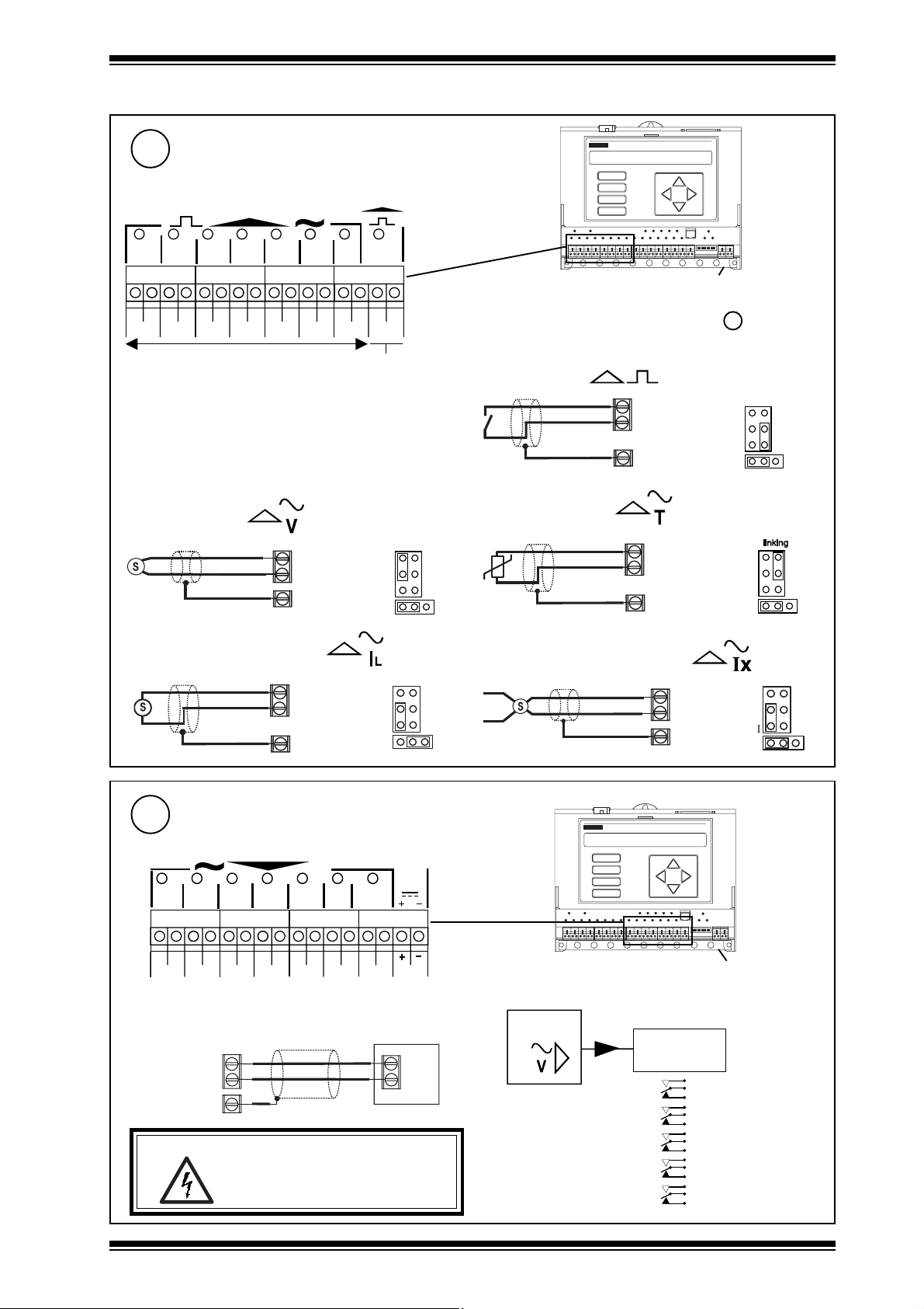
1.3 Installation - Mounting (continued)
7
Connect Inputs
External channels 1 to 8, configuration channels IN1 to IN8
IN1
1
CIN2
2
3
4
C
IN3 C IN4 C IN5 C IN6 C IN7 C IN8 C
Universal Inputs
6
5
78
Digital Only Input
Trend TP/1/1/22/HF/200 (Belden 8761) cable recommended
for all inputs
Terminal size 0.5 to 2.5 mm2 (14 to 20 AWG)
Analogue inputs
Voltage input (channels 1 to 7)
V ( 0 t o 1 0 V )
Current input (loop powered)
®
1
( 0 t o 2 0 m A )
S I G
I N n
C ( 0 V )
e a r t h
( g r o u n d ) b u s
I N n
C ( 2 4 V )
e a r t h
( g r o u n d ) b u s
(channels
1 to 7)
l i n k i n g
1
L
1
A
B
C
D
1 2 3 4 5 67 8 9 1 0
earth (ground) bus
Note that input links are described in Installation
Instructions - sheet 2 Configuration step 10
Digital inputs
(channels 1 to 8)
I N n
C ( 0 V )
e a r t h ( g r o u n d ) b u s
Thermistor input (channels 1 to 7)
I N n
C ( 0 V )
0 V
e a r t h
( g r o u n d ) b u s
Current input (external powered)
T
T
(channels
1 to 7)
S I G
®
0 V
1
( 0 t o 2 0 m A )
I N n
C ( 0 V )
e a r t h
( g r o u n d ) b u s
l i n k i n g
1 N
8
External channels 9 to 15, configuration channels OP1 to OP7
Trend TP/1/1/22/HF/200 (Belden 8761) cable recommended
Connect Voltage Outputs (channels 9 to 15)
V
910
C
OP2
OP1
11
12
13
14
COP3COP4 C OP5 C OP6COP7 C
24V
15
AUX
A
B
C
D
Additional Relay Modules
1 2 3 4 5 67 8 9 1 0
earth (ground) bus
for voltage outputs
Terminal size 0.5 to 2.5 mm2 (14 to 20 AWG)
B n
O P n
C
e a r t h
( g r o u n d ) b u s
WARNING:The wires may be connected to hazardous
voltages. Disconnect power
before attempting any wiring.
l o a d
IQ22x
Relay
Module
SRMV =
2SRM =
2RM = x 2
3RM = x 3
nRM
x 1
x 2
(R/L, H/L)
(HCM/TRM)
6RM = x 6
IQ22x Series Contollers Installation Instructions TG200001 Issue 1/G 08/05/06
1 - 3
Page 4
IQ22x Installation Instructions - Mounting
NC
NO
C
power
actuator
n
NC
NO
C
n+1
raise
lower
C
R
L
common
link
NC NO C16NC NO C17NC NO C18NC NO C19NC NO C
20
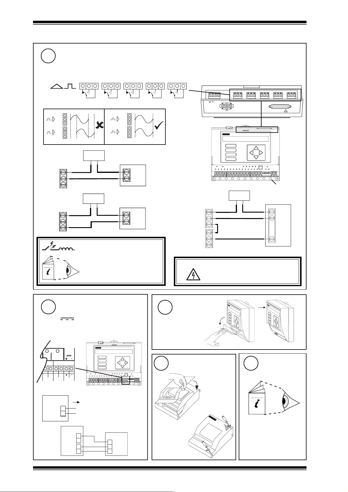
1.3 Installation - Mounting (continued)
9
Connect Relay Outputs
External channels 16 to 20, configuration channels OP8 to IP12
Terminal size 0.5 to 2.5 mm2 (14 to 20 AWG)
n+1
n
Driver on,
load on
C
NO
NC
n
Driver off,
load on
C
NO
NC
n
Æ
a
Æ
b
power
power
n+1
Æ
a
n
Æ
a
load
load
240 Vac single phase 8 A (resistive) 5 A (inductive, Cos
ø = 0.4)
30 Vdc at 5 A (resistive), 20 Vdc at 5 A (inductive)
24 Vdc (inductive) 2 A
For IQ22x/USA, UL rating applies up to 30 V
2 3 0 V
N C N O C N C N O C N C N O C N C N O C N C N O C
~
~
2 4 V
A
B
C
D
M O D E M
1 2 3 4 5 67 8 9 1 0
earth (ground) bus
2 outputs raise/lower
R D S / R S 2 3 2
!
Arc suppression
recommended
Relay Output Arc Suppression
Installation Instructions TG200208
10
Connect Auxiliary Supply
24 V
Terminal size 0.5 to 2.5 mm2 (14 to 20 AWG)
14
15
OP6COP7 C
24V
AUX
A
B
C
D
1 23 4 5 67 8 9 10
IQ22x
24V
+
-
Imax = 100 mA
11
12
a
WARNING: The wires may be connected to
hazardous voltages. Disconnect power
before attempting any wiring.
Close Flap
Close MBOX
if fitted in
ENCLS/MBOX /
IQ22x
13
Configure/
Commission
2
b
e.g.
1 - 4
I Q 2 2 x
+
2 4 V
-
C
O P n
2 R M
2 4 V
0 V
I N
IQ22x Installation Instructions
- Sheet 2: Configuration
IQ22x Series Contollers Installation Instructions TG200001 Issue 1/G 08/05/06
Page 5

Installation Instructions - Configuration
A
D
D P
C
B
12 34 56 78 91 0
SHEET 2: Installation Instructions - Configuration
2.1 Installation - Configuration
IQ22x
Series Controllers
Mount Unit
1
1
IQ22x Installation Instructions - Sheet 1: Mounting
Isolate I/O, Network
3
O
I
WARNING: The connecting leads may be connected to
5
a
supplies. Isolate before touching.
Open MBOX
if unit fitted in ENCLS/MBOX/IQ22x
b
6
WARNING:
Switch off
2
Open Panel
2
4
IQ22x/USA only
The unit is UL rated as 'UL916,
listed open energy management
equipment'
WARNING: Opening the panel may expose
Open Flap
a
dangerous voltages.
417-IEC-5036
b
O
I
LA N
20
17
18
16
19
LA N
TX R X
V
1
2 3 4 5
24 V
6 7 8
9 101112
13
15
14
Removal of the cover
exposes dangerous
voltages.
417-IEC-5036
Disconnect I/O
7
O N
IQ22x Series Contollers Installation Instructions TG200001 Issue 1/G 08/05/06
Set the Network Baud Rate
8
1
284
1 6
3 2
6 4
19k2 baud
9k6 baud
1k2 baud
A
B
C
D
1 K 2
9 K 6
1 9 K 2
1 K 2
9 K 6
1 9 K 2
1 K 2
9 K 6
1 9 K 2
1 K 2
9 K 6
1 9 K 2
Baud Rate = B
= B
1 2 3 4 5 67 8 9 1 0
= B
= B
= B
2 - 1
Page 6

IQ22x Installation Instructions - Configuration
1 2 3 45 6 7 8 9 10
2.1 Installation - Configuration (continued)
Set the Network Address
9
A
B
C
D
1 2 34 5 6 7 8 91 0
O N
e.g.
1
284
Address = 2 + 16 = 18
SET
1 6
3 2
6 4
1 K 2
9 K 6
1 9 K 2
B A U DA D D R E S S
address
NOT SET
Address = A
1, 4 to 9, 11 to 119
= A
/
= A
IQ22x
= A
/
10
Remove Cover
a
A
B
C
D
1 2 34 5 6 7 8 9 10
b
Caution: This unit contains static sensitive
devices. Suitable anti-static
precautions should be taken
throughout this operation to prevent
damage to the unit.
BS EN100015/1 Basic Specification: protection of
electrostatic sensitive devices
c
0, 2 ,3 ,10 or >119
Link Input Channels
11
IL :Current input (Loop Powered)
IX :Current input (External
Powered)
= A
/
V
T D
I
L
I
X
2 - 2
12
Replace Cover
Close Flap
13
a
b
IQ22x Series Contollers Installation Instructions TG200001 Issue 1/G 08/05/06
Page 7

Installation Instructions - Configuration IQ22x
IQ22x
?
IQ22x
?
IQ22x
TX- TX+ RX- RX+
LAN
2.1 Installation - Configuration (continued)
14
16
Switch on
O
I
Check Network
A
B
C
D
1 2 3 4 5 67 8 9 1 0
Check Controller
15
a (power)
b (watchdog)
(green)
(red)
aRX
bTX
c OK
(yellow)
(yellow)
(green)
Check input
power supply
IQ Faulty
A
B
C
D
1 2 3 4 5 67 8 9 1 0
LAN
TX- TX+ RX- RX+
17
OK
Configure
SET
IQ Faulty
X.IQ2
IQ Configuration Manual 90-1533
IQ22x Data Sheet TA103498
SET Manual TE200147
Network Address Invalid
0,2,3 or >119
OK
Check network cabling for
short circuits with a
multimeter (NOT Megger)
O
I
Check baud rate .
Power up other nodes
until faulty node is found
(OK ). Correct fault.
OR
IQ22x
A
B
IQ22x
9 Way 'D type'
Female
also set time, day, date
IQ22x Series Contollers Installation Instructions TG200001 Issue 1/G 08/05/06
Cable/EJ101442
C
D
12 34 56 78 910
RJ11
2 - 3
Page 8

IQ22x Installation Instructions - Configuration
IQ22x
S
IQ22x
S
2.1 Installation - Configuration (continued)
18
19
20
Test Inputs
Switch off
a
O
b
A
B
C
D
12 34 56 78 91 0
I
Test Outputs
Switch off Switch on
a
b
A
B
C
O
I
D
12 34 56 78 91 0
c
Backup
SET Manual TE200147
SET
(compare)
Switch on
c
O
I
d
O
I
IQ22x
(yellow)
d
e.g. VB
(yellow)
IQ22x
(yellow)
A
B
C
D
A
B
C
D
A
B
C
D
ΔT = X
12 34 56 78 910
12 34 56 78 910
12 34 56 78 910
IQ22x
a
21
X.IQ2
IQ22x
Close MBOX
if fitted in
ENCLS/MBOX/IQ22x
b
9 Way 'D type'
Female
Cable/EJ101442
Close Panel
22
IQ22x/USA only
The unit is UL rated as 'UL916, listed
open energy management equipment'
1 7
2 0
1 8
1 6
1 9
TX R X
V
24 V
2 3 4 5
1 1
6 7 8
9 10
1 2
1 3
1 5
1 4
1
A
B
C
D
12 34 56 78 910
OR
RJ11
Fit Options
23
as required
3
LA N
LA N
IQ22x Installation Instructions Sheet 3: Options
2.2 Disposal
WEEE Directive :
At the end of their useful life the packaging ,
product, and battery should be disposed of by
Do not dispose of with normal household waste.
Do not burn.
2 - 4
a suitable recycling centre.
IQ22x Series Contollers Installation Instructions TG200001 Issue 1/G 08/05/06
Page 9

Installation Instructions - Options
2 2 0
Series Controllers
SHEET 3: Installation Instructions - Options
3.1 Connecting a Remote 2-line Display (if KIT/2xx/RDS has been fitted)
IQ22x
Ensure /RDS
Installed
1 (FPK or HDP)
23 0V
~
KIT/2xx/RDS Installation
Instructions - IQ22x,
241/242
TG103128
Connect Display
2
NC NO C NC NO C N C N O C N C N O C NC NO C
~
24 V
R DS /R S2 32
M OD E M
!
V
24 V
I Q
3.2 Connecting to PC using Supervisor Port
1
Connect RS232
IQ22x
A
B
C
9 F'D'
Cable/EJ101442
D
12 34 56 78 910
RJ11
Test
3
4
3
Display Panel
Manual 90-1505
Configure Address
2
SET
sUpervisor port addr = 1,4 to 9, 11 to 119
IQ Configuration Manual 90-1533
IQ22x Data Sheet TA103498
sUpervisor port addr = 0
angle adjust screw
Adjust Viewing
Angle
if faint
3.3 Connecting to NDP using Supervisor Port
1
2
Note that this will consume
75 mA of the available 24
Vdc supply current.
IQ22x Series Contollers Installation Instructions TG200001 Issue 1/G 08/05/06
Configure Address
See above 'Connecting to PC using Supervisor port' Steps 1 & 2
Configuration Mode, addRess Module
Switch Off
O
I
9 Way
'D' Female
Compatibility
Connect NDP to Controller
3
+
-
Cable/EJ104029
85400180___<rebmunlaireSPDNV03<cdV42/ro032/x22QI
85400180___>rebmunlaireSPDNsnoitporewoplla/x22QI
A
B
C
D
sUpervisor port addr = 1,4 to 9, 11 to 119
sUpervisor port addr = 0
Switch On
4
O
1
1 23 4 56 7 89 10
RJ11
Test
5
3 - 1
Page 10

IQ22x Installation Instructions - Options
A
D
D P
C
B
12 34 56 78 91 0
3.4 Mounting in an Enclosure, ENCLs/...
Open Door
1
a
b
2
Drill Wall
560 mm
3
No. 12
Mount on Wall
OR
560 mm
Remove Backplate
4
Mount IQ22x on Backplate
5
b
Replace Backplate
6
M6
a
c
M6
3.5 Replacing the Battery
Upload Strategy
1
SET
X.IQ2
OR
IQ22x
Isolate I/O, Network
3
WARNING:The
Isolate before touching.
connecting
leads may be
connected
to supplies.
O
I
SET Manual TE200147
9 'D type'
Female
Cable/EJ101442
See above, "3.2 Connecting PC using
Supervisor Port"
IQ22x
A
B
C
D
Open Panel
4
LA N
17
20
18
16
19
TX R X
V
24V
1
6 7 8
9 101112
2 3 4 5
13
15
14
Switch Off
2
O
12 34 56 78 910
RJ11
IQ22x/USA only
The unit is UL rated as 'UL916,
listed open energy
management equipment'
LA N
WARNING: Opening the panel
may exposes
dangerous voltages.
417-IEC-5036
I
3 - 2
Open MBOX
5
if unit fitted in ENCLS/MBOX/IQ22x
a
b
6
a
Open Flap
b
WARNING: Removal of
the cover
exposes
dangerous
voltages.
417-IEC-5036
IQ22x Series Contollers Installation Instructions TG200001 Issue 1/G 08/05/06
Page 11

Installation Instructions - Options IQ22x
A
D
D P
C
B
12 3 45 67 89 10
3.5 Replacing the Battery (continued)
Remove Cover
7
a
A
B
C
D
1 2 34 5 6 7 8 9 10
b
c
Caution: This unit contains static
sensitive devices.
Suitable anti-static
precautions should be
taken throughout this
operation to prevent
damage to the unit.
BS EN100015/1 Basic Specification:
protection of electrostatic sensitive devices
Replace Battery
8
12345678910
Warning: The lithium battery must not be recharged,
+
13
SET cannot download
over autodial link
X.IQ2
disassembled, burnt or short circuited.
Misuse may cause explosion or fire.
Dispose of carefully. Refer to Health and
Safety Executive Guidance Note GS43.
Download Strategy
SET
OR
IQ22x
9
Saft
LM2450
3V
11
10s
SET Manual TE200147
9 'D type'
Female
Cable/EJ101442
Replace Cover
Wait
IQ22x
A
B
C
D
12 34 56 78 910
RJ11
Switch On
10
O
I
Reset RAM
If not IQ2v3 (IQ2v3 will
12
reset RAM automatically)
Switch off. Complete Zero
Address/Baud Rate Switch
Reset section steps 2 to 7.
Close Flap
14
ba
Also set time, day, date.
a
15
Close MBOX
if fitted in
ENCLS/MBOX/IQ22x
IQ22x/USA only
The unit is UL rated as 'UL916,
Close Panel
16
listed open energy management
equipment'
b
1
2 3 4 5
IQ22x Series Contollers Installation Instructions TG200001 Issue 1/G 08/05/06
17
Power Supply to I/O,
Network
LA N
17
20
18
16
19
LA N
TX R X
V
24 V
6 7 8
9 1 01112
13
15
14
3 - 3
Reconnect Input
Page 12

IQ22x Installation Instructions - Options
1
284
1 6
3 2
6 4
1 K 2
9 K 6
1 9 K 2
O N
3.6 Zero Address/Baud Rate Switch Reset
Backup,
Switch Off,
1
Isolate,
Open Flap
Complete 'Replacing
the Battery' steps 1
to 5
Switch On
4
2
O N
1
284
e.g. Address
= 2 + 16 = 18
O
I
Note the Network Address
and Baud Rate
A
B
C
D
1 6
3 2
6 4
1 K 2
9 K 6
1 9 K 2
B A U DA D D R E S S
= 19k2 baud
1 K 2
9 K 6
1 9 K 2
SET
1 9 K 2
1 K 2
9 K 6
= 9k6 baud
= 1k2 baud
1 K 2
9 K 6
1 9 K 2
NOT SET
Wait for Relays
5
Set all Switch Poles
284
A D D R E S S
to Zero
1 6
3 2
6 4
1 9 K 2
B A U D
A
B
C
D
12 3 45 6 78 91 0
9 K 6
1 K 2
NOT SET
3
12 3 45 67 8 910
O N
1
Address = 0 Baud = 0
'click'
Reset the Network Baud Rate
6
Baud Rate = B
19k2 baud
1 K 2
9 K 6
1 9 K 2
= B
9k6 baud
1 K 2
9 K 6
1 9 K 2
1k2 baud
1 K 2
9 K 6
1 9 K 2
Reset the Network Address
7
A
B
C
D
1 23 4 5 6 78 9 10
= B
e.g.
O N
1
284
1 6
3 2
Address = 2 + 16 = 18
SET
6 4
1 9 K 2
B A U DA D D R E S S
NOT SET
1 K 2
9 K 6
= A
/
A
B
C
D
Address = A
= A
IQ22x
1 23 4 5 67 8 9 10
= A
/
= B
= A
/
address
Download Strategy,
= B
1, 4 to 9, 11 to 119
8
Close Flap,
Reconnect Power to
0, 2 , 3,10 or >119
Complete 'Replacing the Battery'
steps 12 to 15
I/O
Manufactured for and on behalf of the Environmental and Combustion Controls Division of Honeywell Technologies Sàrl, Ecublens, Route
du Bois 37,Switzerland by its Authorized Representative, Trend Control Systems Limited.
Trend Control Systems Limited reserves the right to revise this publication from time to time and make changes to the content
hereof without obligation to notify any person of such revisions or changes.
Trend Control Systems Limited
P.O. Box 34, Horsham, West Sussex, RH12 2YF, UK. Tel:+44 (0)1403 211888 Fax:+44 (0)1403 241608 www.trend-controls.com
Trend Control Systems USA
6670 185th Avenue NE, Redmond, Washington 98052, USA. Tel: (425)869-8400, Fax: (425)869-8445 www.trend-controls.com
3 - 4
IQ22x Series Contollers Installation Instructions TG200001 Issue 1/G 08/05/06
 Loading...