

Page 1
Space Humidity and Temperature Sensor
Important: Retain these instructions
Installation Instructions
HT/S
Contents
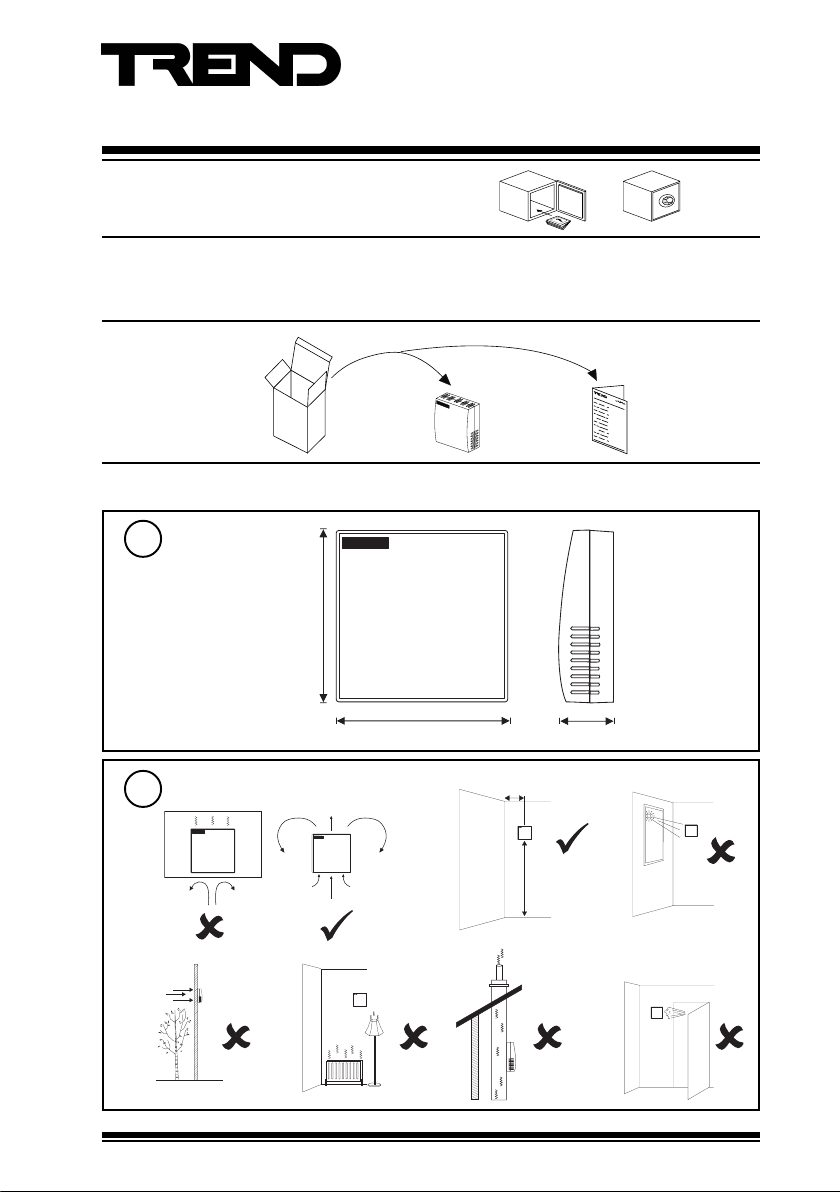
1 Unpacking .................................................... 1
1 Unpacking
2 Installation
Dimensions
1
86 mm (3.39”)
86 mm (3.39”)
Requirements
2
a
2 Installation .................................................... 1
3 Maintenance ................................................. 4
4 Disposal ....................................................... 4
HT/S Installation
Instructions
TG200990
26 mm (1.02”)
> 50 cm (20”)
b
1.5 m
(5 ft)
c
d
HT/S Space Humidity and Temperature Sensor Installation Instructions TG200990 Issue 1/A 30/01/08
e
f
g
1
Page 2
HT/S Installation Instructions
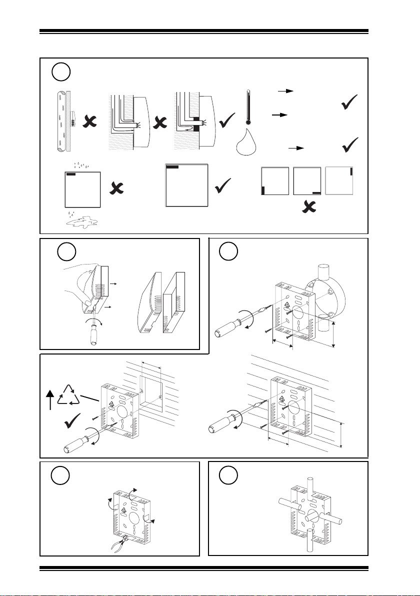
H O
2
2 Installation (continued)
Requirements (continued)
2
h
i
j
-5 °C
(23 °F)
0 °C
(32 °F)
+55 °C
(131 °F)
+40 °C measurement
(104 °F)
a
Remove backplate
3
wall box
FR
ABS
b
lk
60 mm (2.36”)
Mount backplate
4
back box
(BESA)
35 mm (1.38”)
wall
0 %RH
100 %RH
non -condensing
35 mm
(1.38”)
35 mm
(1.38”)
35 mm (1.38”)
Remove cutout(s)
5
as required
2
HT/S Space Humidity and Temperature Sensor Installation Instructions TG200990 Issue 1/A 30/01/08
Route cables
6
Page 3

Installation Instructions HT/S
IQ
2 Installation (continued)
Wire to Controller
7
HT/S
IQ1 & IQ2
2 analogue input channels
TH
TH
I-N
I-P
IN
C
IN
C (+24V)
} temperature
} humidity
linked for thermistor (T)
linked for current (I)
earth (ground) screens at IQ end
IQ3
N+1
temperature
humidity
N
linked for thermistor (T)
linked for current (I)
HT/S/2%
0 (0V)
N+1 (in)
TH
TH
I-N
I-P
+ (+24V)
0 (0V)
N (in)
+ (+24V)
earth (ground) screens at IQ end
IQ1 & IQ2
IN
} temperature
I2N
I1N
I-P
C (+24V)
IN
C (+24V)
} humidity
linked for current (I)
linked for current (I)
earth (ground) screen at IQ end
Note that when connecting to IQ3, in order to provide sufficient supply current to the sensor, the
sensor I-P terminal must be connected to both channels’ 24 V terminals.
0 (0V)
N+1 (in)
I2N
I1N
I-P
+ (+24V)
0 (0V)
N (in)
+ (+24V)
IQ3
N+1
temperature
humidity
N
linked for current (I)
linked for current (I)
Note that in order to maintain the HT/S/2% temperature sensor accuracy, the temperature sensor
earth (ground) screen at IQ end
should only be used if the humidity sensor is also used.
8
backplate
Assemble unit
‘click’
9
Configure IQ
or
IQ
IQ Configuration
Manual 90-1533
HT/S Space Humidity and Temperature Sensor Installation Instructions TG200990 Issue 1/A 30/01/08
3
Page 4

HT/S Installation Instructions
2 Installation (continued)
10
Set up IQ Sensor types
It is recommended to use SET (software tool) for the setting of sensor type modules. For all IQ2
series controllers with firmware version 2.1 or greater, or IQ3 series controllers, the following SET
Unique Sensor References should be used:
Humidity (HT/S, HT/S/2%): Humidity I
Temperature (HT/S): Thermistor HTST DT (°C)
Thermistor HTST DT F (°F)
Temperature (HT/S/2%): PRT I 0+40 (°C)
Alternatively set scaling mode to 5 (characterise), and enter scaling manually as defined in the
PRT I +32+104 F (°F)
appropriate tables below. Note that for IQ3, scaling mode and exponent do not need to be set up.
For all other IQ controllers see Sensor Scaling Reference Card TB100521A.
Temperature
HT/S (0 to +40 °C, 32 to 104 °F)
stinU
Y
E
U
L
P
xxI)C°(xO)F°(xO
1
2
3
4
5
6
11
C°F°
epyttupnI
3
tnenopxE
05221
reppU
rewoL
5-32
stnioP
6
146.205221
74.304401
64.40368
366.60105
866.7023
201.85-32
Test system
Temperature
I Q
)stlovrotsimreht(1
Temperature
HT/S/2%
(0 to +40 °C, 32 to 104 °F)
C°F°
stinU
Y
E*
U
L
P
xxIxO
1
2
epyttupnI
tnenopxE
reppU
rewoL
stnioP
4023
0204401
)tnerruc(2
3
04401
023
2
Humidity
Δ T
Humidity
HT/S and HT/S/2%
(0 to 100 %RH)
Y epyttupnI)Amrruc(2
E tnenopxE3
U reppU001
L rewoL0
P stnioP2
xxIxO
1 40
2 02001
Δ H
I Q
3 Maintenance
4 Disposal
Over time, the sensing element may become
covered in dust. The dust can be removed
using compressed air. Under no circumstances
should water or cleansing agents be used on the
sensing elements.
Do not dispose of with normal household waste. Do not burn.
Please send any comments about this or any other Trend technical publication to techpubs@trendcontrols.com
Manufactured for and on behalf of the Environmental and Combustion Controls Division of Honeywell Technologies Sàrl, Ecublens,
Route du Bois 37,Switzerland by its Authorized Representative, Trend Control Systems Limited.
©Trend Control Systems Limited 2007. Trend Control Systems Limited reserves the right to revise this publication from time to time and
make changes to the content hereof without obligation to notify any person of such revisions or changes.
Trend Control Systems Limited
P.O. Box 34, Horsham, West Sussex, RH12 2YF, UK. Tel:+44 (0)1403 21888 Fax:+44 (0)1403 241608 www.trend-controls.com
WEEE Directive :
At the end of their useful life the packaging
and product should be disposed of by a
suitable recycling centre.
Trend Control Systems USA
6670 185th Avenue NE, Redmond, Washington 98052, USA. Tel: (425)897-3900, Fax: (425)869-8445 www.trend-controls.com
4
HT/S Space Humidity and Temperature Sensor Installation Instructions TG200990 Issue 1/A 30/01/08
 Loading...