

Page 1
Outside Humidity and Temperature Sensor
HO
2
Important: Retain these instructions
Installation Instructions
HT/O
CONTENTS
1 Unpacking.......................................................................... 1
2 Installation .......................................................................... 1
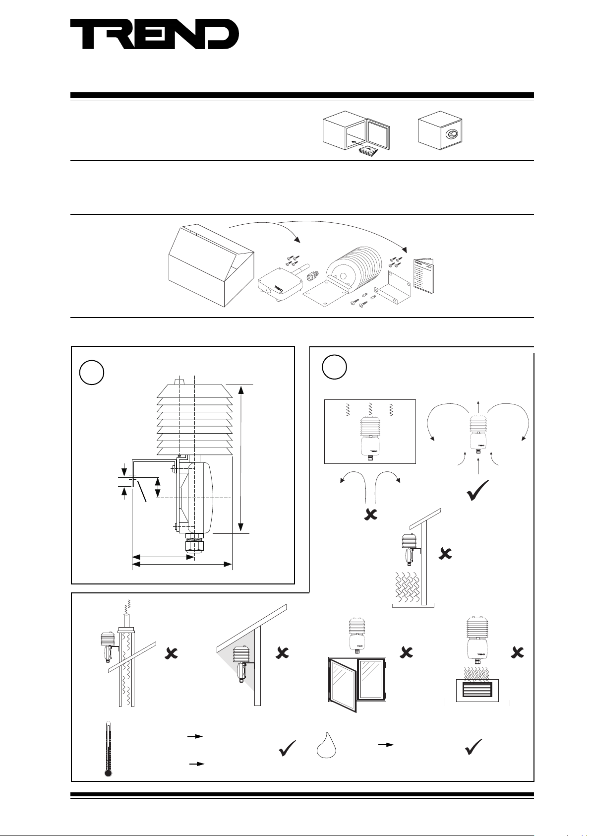
1 Unpacking
2 Installation
1
Dimensions
3 Fault Finding ...................................................................... 4
4 Maintenance ...................................................................... 5
5 Disposal ............................................................................. 8
HT/O Installation
Instructions TG200992
2
Requirements
a
196 mm, 7.72”
0.87”
Ø 5 mm
0.2”
112 mm, 4.4”
22 mm
d
+60 °C (+140 °F)
+50 °C (+122 °F)
b
e
0 %RH 100 %RH
Protection: IP65
f
10 mm, 0.39”
69.5 mm, 2.74”
c
g
ambient limit
-40 °C (-40 °F)
measurement
-30 °C (-22 °F)
HT/O Installation Instructions TG200992 Issue 1/A 30/01/08
1
Page 2
HT/O Installation Instructions
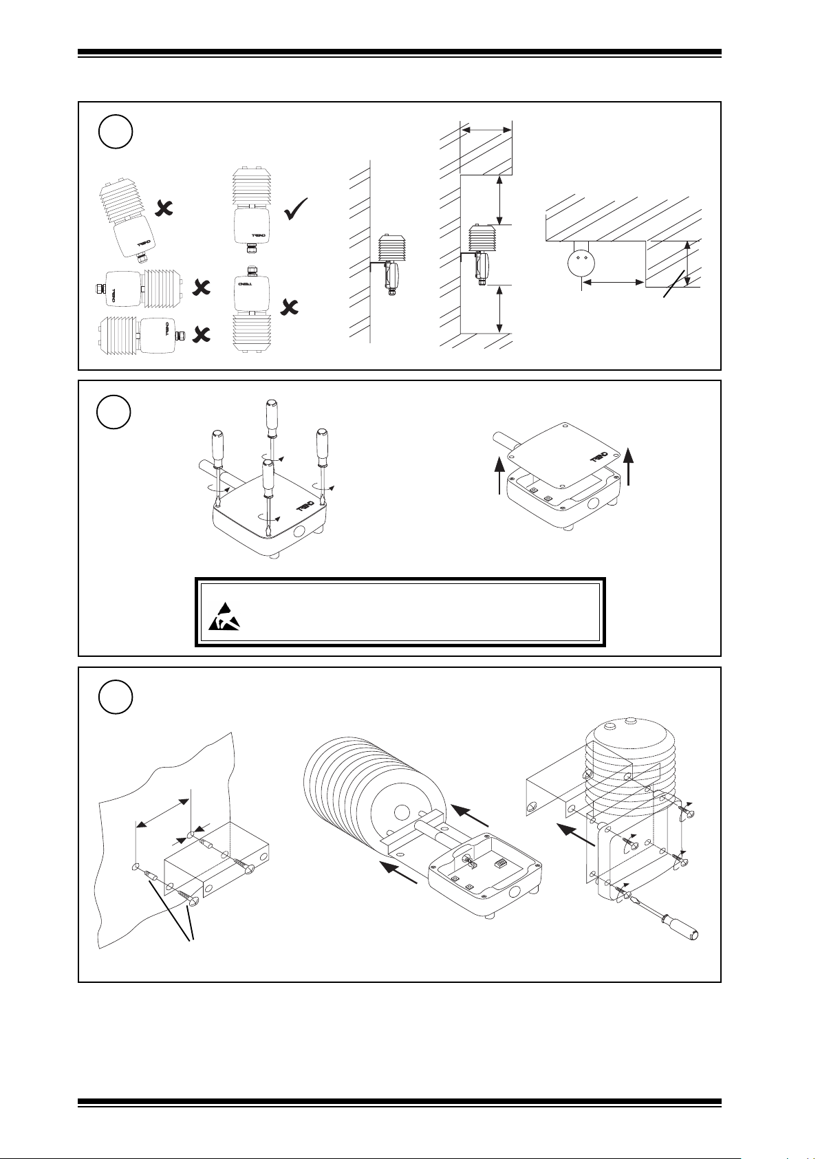
2 Installation (continued)
2
h
3
Requirements (continued)
Remove Cover
a
ij k
b
B1 < L1
L1
> 1 m, 1 yd
L2
B2 < L2
Caution: This unit contains static sensitive devices. Suitable anti-static precautions
4
Fit Bracket, Shield and Sensor
a
44 mm (1.73”)
2 wallplugs and screws supplied
Ø 6 mm (0.24”)
should be taken throughtout the operation to prevent damage to the units.
BS EN100015/1 Basic Specification: protection of electrostatic sensitive
devices.
c
b
2
HT/O Installation Instructions TG200992 Issue 1/A 30/01/08
Page 3
Installation Instructions HT/O
I Q
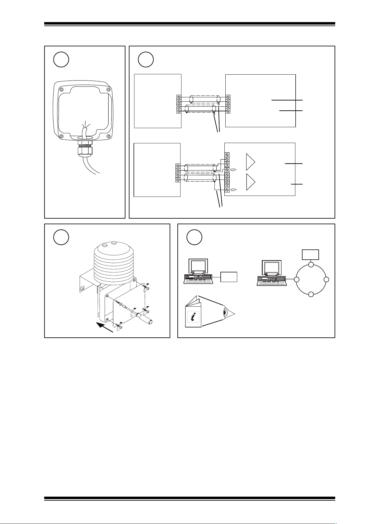
2 Installation (continued)
5
7
Insert Cable
through gland
M16 gland
Fit Cover
6
Wire to Controller
V+
RH
T
Tp
V+
RH
T
Tp
8
IQ1 & IQ2
C (+24V)
} humidity
IN
C
} temperature
IN
earth (ground) screens at IQ end
N
N+1
IQ3
humidity
temperature
0 (0V)
N (in)
+ (+24V)
0 (0V)
N+1 (in)
+ (+24V)
earth (ground) screens at IQ end
Configure IQ
2 analog input
channels
linked for
current (I)
linked for
thermistor
(T)
linked for
current (I)
linked for
thermistor
(T)
or
I Q
IQ Configuration Manual 90-1533
HT/O Installation Instructions TG200992 Issue 1/A 30/01/08
3
Page 4

HT/O Installation Instructions
2 Installation (continued)
9
Set up IQ Sensor types
It is recommended to use SET (Software Tool) for the setting of the sensor type module. For all IQ2 series controllers with
firmware version 2.1 or greater, or IQ3 series controllers, the following SET Unique Sensor References should be used:
Humidity :Humidity I
Temperature :Thermistor HTOT (°C)
Thermistor HTOT F (°F)
Alternatively enter scaling manually as defined in tables below.
For all other IQ contriollers see Sensor Scaling Reference Card TB100521A
Temperature (thermistor)
(-30 to +50 °C, -22 t0 122 °F)
10
Test System
:stinUC°F°
Y
E
U
L
P
xxIxO
1 146.205221
2 074.304401
3 064.40368
4 366.60105
5 866.7023
6 201.85-32
7 284.801-41
8 708.851-5
9 870.902-4-
epyttupnI
tnenopxE
reppU
rewoL
stnioP
01 992.952-31-
11 674.903-22
)Vmreht(1
3
55131
53-13-
11
-
Humidity (current)
(0 to 100 %RH)
Y
E
U
L
P
xxIxO
1 40
2 02001
epyttupnI
tnenopxE
reppU
rewoL
stnioP
)Amrruc(2
3
001
0
2
3 Fault Finding
stluaFsesuaCelbissoPseidemeR
emitesnopsergnoLdetullopretliFretlifecalpeR
eruliafetelpmoCylppusrewopoN elbacdn
hgihootgnidaerytidimuHeborprosnesnonoitasnednoC yrassecenfiretlifecalperdnaeborpyrD
IQ
Δ H
aylppusrewopkcehC
Δ T
4
HT/O Installation Instructions TG200992 Issue 1/A 30/01/08
Page 5

Installation Instructions HT/O
U P
D O W N
4 Maintenance
Over time, the sensing element may become covered in dust. The dust can be removed using compressed air. Under no
circumstances should water or cleansing agents be used on the sensing elements.
It is recommended that the accuracy of the sensor is verified every 12 months. If the sensor falls outside the quoted accuracy,
replace the filter and recalibrate as shown below:
1
2
Remove Cover
Caution: This unit contains static sensitive devices.
Suitable anti-static precautions should be taken
throughtout the operation to prevent damage to
the units.
BS EN100015/1 Basic Specification: protection of
electrostatic sensitive devices.
Detach Sensor
3
Remove from Radiation Shield
4
Replace filter
a unscrew
See Section 5, Disposal
b
d
c ACC/HTO/FILTER
Caution: Do not touch humidity sensing element
Preparation
5
• Keep sensor and humidity chamber in same room for
4 hours before.
• Place probe in humidity chamber 30 mins before.
• Keep temperature constant during calibration.
Locate buttons
6
push
buttons
U P
D O W N
calibration
LED
HT/O Installation Instructions TG200992 Issue 1/A 30/01/08
5
Page 6

HT/O Installation Instructions
4 Maintenance (continued)
7
• Start calibration at lower humidity point.
• Difference between the two points should be >30%RH
Low Humidity Calibration
1 Remove lid from the calibration chamber (ACC/CAL/HT)
and clean chamber thoroughly.
2 Insert one of the cloths provided with the calibrating
liquid. Pour calibrating liquid (ACC/CAL/HT/35%) onto
the fabric. Refit lid and screw tightly.
3 Insert probe into sensor aperture of chamber and tighten
collar to provide air tight seal around the probe. Wait
30 min.
4 Press Down pushbutton for 3 s to start. LED will illuminate.
5 Press Up or Down pushbutton to adjust measured value
in 0.1% steps.
6 Either: Press Up pushbutton for 3 s to stop. Calibrated
value is stored. LED is extinguished.
Or: Press Down pushbutton for 3 s to exit calibration
without storing value. LED is extinguished.
8
• This calibration decreases accuracy over remainder of
working range
Single Point Humidity Calibration
1 Remove lid from the calibration chamber (ACC/CAL/HT)
and clean chamber thoroughly.
2 Insert one of the cloths provided with the calibrating
liquid. Pour calibrating liquid (ACC/CAL/HT/35% or /
80%) onto the fabric. Refit lid and screw tightly.
3 Insert probe into sensor aperture of chamber and tighten
collar to provide air tight seal around the probe. Wait
30 min.
4 Either: (If chamber humidity >50%RH.) Press Up
pushbutton for 3 s to start. LED will illuminate.
Or: (If chamber humidity <50%RH.) Press Down
pushbutton for 3 s to start. LED will illuminate.
5 Press Up or Down pushbutton to adjust measured value
in 0.1% steps
6 Either: Press Up pushbutton for 3 s to stop. Calibrated
value is stored. LED is extinguished.
Or: Press Down pushbutton for 3 s to exit calibration
without storing value. LED is extinguished.
For calibration over whole working range
One point calibration
For calibration over limited range about single point
Two point calibration
High Humidity calibration
7 Remove lid from the calibration chamber (ACC/CAL/HT)
and clean chamber thoroughly.
8 Insert one of the cloths provided with the calibrating
liquid. Pour calibrating liquid (ACC/CAL/HT/80%) onto
the fabric. Refit lid and screw tightly.
9 Insert probe into sensor aperture of chamber and tighten
collar to provide air tight seal around the probe. Wait
30 min.
10 Press Up pushbutton for 3 s to start. LED will illuminate.
11 Press Up or Down pushbutton to adjust measured value in
0.1% steps
12 Either: Press Up pushbutton for 3 s to stop. Calibrated
value is stored. LED is extinguished.
Or: Press Down pushbutton for 3 s to exit calibration
without storing value. LED is extinguished.
9
Replace Radiation Shield
10
6
Re-attach Sensor
11
HT/O Installation Instructions TG200992 Issue 1/A 30/01/08
Replace Cover
Page 7

Installation Instructions HT/O
4 Maintenance (continued)
12
Test System
IQ
Δ T
Δ H
HT/O Installation Instructions TG200992 Issue 1/A 30/01/08
7
Page 8

HT/O Installation Instructions
5 Disposal
WEEE Directive :
At the end of their useful life the packaging and
product should be disposed of by a suitable
Do not dispose of with normal household waste.
Do not burn.
recycling centre.
Please send any comments on this or any other Trend technical publication to techpubs@trendcontrols.com
Manufactured for and on behalf of the Environmental and Combustion Controls Division of Honeywell Technologies Sàrl, Ecublens, Route du
Bois 37,Switzerland by its Authorized Representative, Trend Control Systems Limited.
©Trend Control Systems Limited 2007. Trend Control Systems Limited reserves the right to revise this publication from time to time and make
changes to the content hereof without obligation to notify any person of such revisions or changes.
Trend Control Systems Limited
P.O. Box 34, Horsham, West Sussex, RH12 2YF, UK. Tel:+44 (0)1403 211888 Fax:+44 (0)1403 241608 www.trend-controls.com
Trend Control Systems USA
6670 185th Avenue NE, Redmond, Washington 98052, USA. Tel: (425)897-3900, Fax: (425)869-8445 www.trend-controls.com
8
HT/O Installation Instructions TG200992 Issue 1/A 30/01/08
 Loading...