

Page 1
Installation Instructions
ENCLS/...
Enclosures
Important: keep these instructions with the unit.
Because these instructions contain information that may be required after installation they should be kept with the unit, or in a location
where they can quickly be found.
Installation
Mount the enclosure in position
Mount the ENCLS in position. The location should provide safe
access for maintenance, and a suitable operating environment.
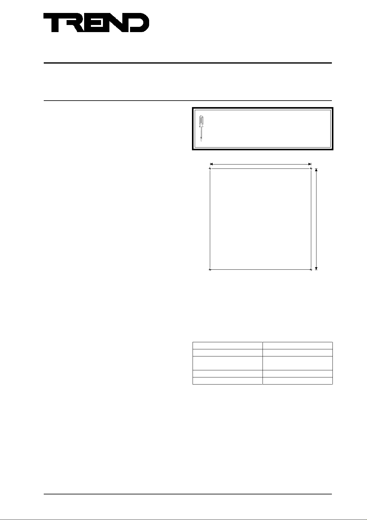
(1) Drill 4 off 12 mm holes as shown.
(2) Insert suitable expanding fixing (e.g. rawlbolt)
through each hole in the enclosure, into the
mounting holes, and tighten.
It is recommended that the installation should comply
with the HSE Memorandum of Guidance on Electricity
at Work Regulations 1989.
560 mm
560 mm
Fit the item into the enclosure
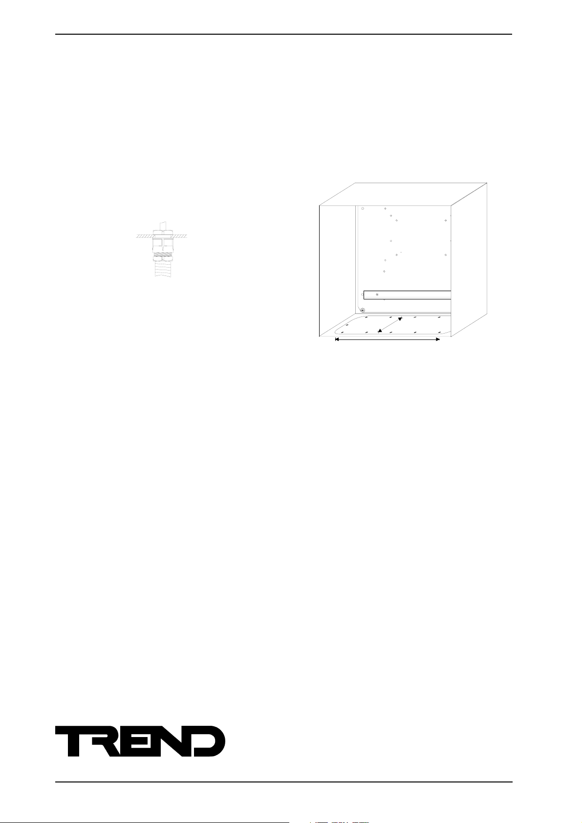
(3) If fitting an IQ25x controller into the enclosure
remove the DIN rail by undoing the two fixing
screws.
(4) Locate the pre-drilled mounting holes in the
enclosure’s backplate needed by the item being
mounted in the enclosure. The table lists the
types of items that can be fitted in the enclosure.
(5) Insert the screws provided through the mounting
holes in the controller or NETB, into the pre-drilled
mounting holes in the enclosure’s backplate.
that it may be necessary to remove the controller’s
covers to gain access to the mounting holes; this
is described in the installation instructions for
the particular controller or NETB.
Connect the item to the Display Panel, or Network Display Panel
(6) Connect the DP, or NDP in the door of an
ENCLS/FPK, or ENCLS/NDP to the controller or
NETB/.. mounted inside the enclosure. This is
described in the controller’s or NETB installation
instructions, or data sheet.
Note
IQ91e IQ131+
IQ92e IQ151+
IQ93e IQ241
IQ101+ IQ250
IQ102+ IQ251
IQ111+ NETB/NETBB
ENCLS/... Enclosures Installation Instructions TG103175 Issue 1/A 1/7/96 1
Page 2
ENCLS/... ENCLOSURES
Installation (Continued)
Route any cables
(7) Drill 20 mm holes for M20 copex type cable glands
in the positions required in the gland plate
(8) Route the cables for the I/O, network, and
controller power into the enclosure through the
cable glands.
Install the controller
(9) Complete the installation of the controller or NETB
as described in the relevant installation
instructions.
use copex glands
Installation Instructions
Note that the DIN rail may be used for mounting relay modules
(2RM etc) or other interface nodes (e.g. 4DIX etc).
150 mm
530 mm
Trend Control Systems Ltd reserves the right to revise this publication from time to time and make changes to the content hereof
without obligation to notify any person of such revisions or changes.
Trend Control Systems Ltd. P.O. Box 34 Horsham Sussex RH12 2YF England Tel:+44 (0)1403 211888 Fax:+44 (0)1403 241608 www.trend-controls.com
2
ENCLS/... Enclosures Installation Instructions TG103175 Issue 1/A 1/7/96
 Loading...