

Page 1

Three Phase Electricity Meter
Important: Retain these instructions
UNPACKING
Installation Instructions
EM/RX2
EM/RX2 Installation
Instructions
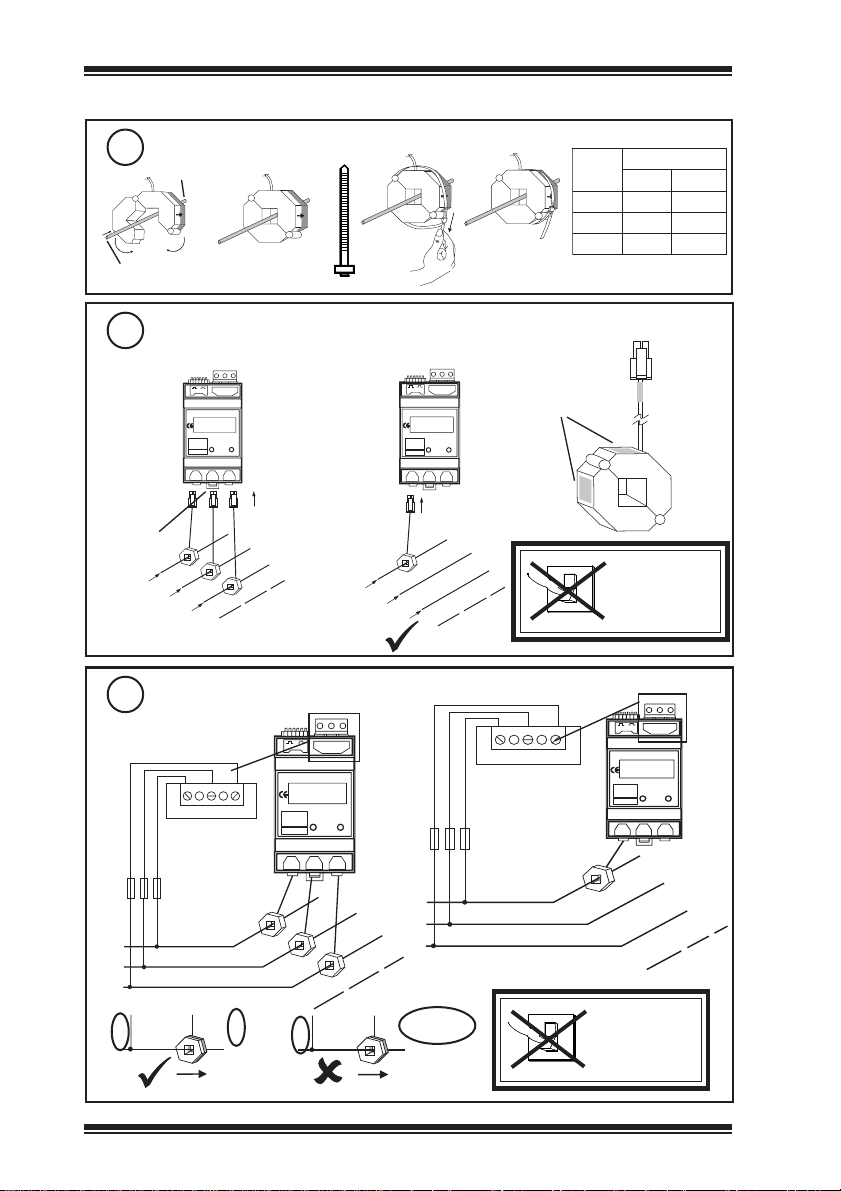
INSTALLATION
Dimensions
1
54 mm (2.12”)
Output
V2
V1
24vMax
VoltsInput
DUALPULSE
MULTIFUNCTION
ENERGYMETER
KLIK 2
Pulse
SINERGYLTD.
SK67GPENGL AND
Tel:01663764833
PAGE
SET
CT2 CT3
CT1
Choose location
2
Output
V3
V2
V1
24vMax
VoltsInput
DUALPULSE
MULTIFUNCTION
ENERGYMETER
KLIK 2
Pulse
SINERGYLTD.
SK67GPENGLAND
Tel:01663764833
PAGE
SET
CT2 CT 3
CT1
Pulse
access for cables
V3
60 mm
(2.36”)
access for cables
maximum
2m (6’ 7”)
Output
V3
V1
V2
24vMax
VoltsInput
DUALPULSE
MULTIFUNCTION
ENERGYMETER
KLIK2
Pulse
SINERGYLTD.
SK67GPENGLAND
Tel:01663764833
PAGE
SET
CT2 CT3
CT1
2 m (6’ 7”)
3 x CT
92 mm (3.62”)
Output
V3
V1
V2
24vMax
VoltsInput
DUALPULSE
MULTIFUNCTION
ENERGYMETER
KLIK 2
Pulse
SINERGYLTD.
SK67GPENGLAND
Tel:01663764833
PAGE
SET
CT2 CT3
CT1
110 mm (4.23”)
It is recommended that the installation should
comply with the HSE Memorandum of
Guidance on Electricity at Work Regulations
1989. For USA install equipment in
accordance with the National Electric Code.
Choose location (continued)
2
Output
V3
V2
V1
24vMax
VoltsInput
DUALPULSE
MULTIFUNCTION
ENERGYMETER
KLIK2
Pulse
SINERGYLTD.
SK67GPENGLAND
Tel:01663764833
PAGE
SET
CT2 CT3
CT1
Output
V3
V2
V1
24vMax
VoltsInput
DUALPULSE
MULTIFUNCTION
ENERGYMETER
KLIK2
Pulse
SINERGYLTD.
SK67GPENGLAND
Tel:01663764833
PAGE
SET
CT2 CT3
CT1
Protection :IP20
-10 °C
(14 °F) (131 °F)
0 %RH 95 %RH
H O
2
Fix on DIN Rail
3
a
+55 °C
b
KLIK 2
CT1
Output
V3
V2
V1
24vMax
VoltsInput
DUALPULSE
MULTIFUNCTION
ENERGYMETER
Pulse
SINERGYLTD.
SK67GPENGLAND
Tel:01663764833
PAGE
SET
CT2 CT3
c
EM/RX2 Three Phase Electricity Meter Installation Instructions TG200133 Issue 3 04/03/08
1
Page 2
EM/RX2 Installation Instructions
INSTALLATION(continued)
Fit CTs to Conductors
4
a
LOAD
b
I
SUPPLY
Connect Meter to CTs
5
if 3CTs (balanced or unbalanced)
Output
V3
V1
V2
24vMax
VoltsInput
DUALPULSE
MULTIFUNCTION
ENERGYMETER
KLIK 2
Pulse
SINERGYLTD.
SK67GPENGL AND
Tel:01663764833
PAGE
SET
CT2 CT3
CT1
(Brown)
CT2
(Black)
SUPPLY
CT1
CT3
(Grey)
L1
L2
L3
N
V
L-L
c
LOAD
SUPPLY
= 380 to 450 V
d
e
if 1CT (balanced only)
Output
V3
V2
V1
24vMax
VoltsInput
DUALPULSE
MULTIFUNCTION
ENERGYMETER
KLIK 2
Pulse
SINERGYLTD.
SK67GPENGL AND
Tel:01663764833
PAGE
SET
CT2 CT3
CT1
CT1
(Brown)
LOAD
L1
L2
L3
N
Brown
2XR/ME
002/A002A004
005/A005A0001
0001/A0001A0002
O
I
SWITCH ON
xamI
gnikroWdaolrevO
DO NOT
Connect Meter to Supply
6
if 3 CTs
(balanced or unbalanced)
V1 V2 V3
2A HRC
SUPPLY
V1
2
CT1
if 1 CT (balanced only)
Output
CT1
L2
24vMax
KLIK 2
CT1
L3
PAGE
CT2 CT3
Output
V3
V2
V1
24vMax
VoltsInput
DUALPULSE
MULTIFUNCTION
ENERGYMETER
KLIK 2
Pulse
SINERGYLTD.
SK67GP ENGLAND
Tel:01663764833
PAGE
SET
CT2 CT3
CT1
CT1
L1
CT2
CT3
LOAD
L2
L3
V1 V2 V3
2A HRC
L1
SUPPLY
N
DO NOT
V1
CT2 or 3
EM/RX2 Three Phase Electricity Meter Installation Instructions TG200133 Issue 3 04/03/08
O
I
SWITCH ON
V1
DUALPULSE
MULTIFUNCTION
ENERGYMETER
SINERGYLTD.
SK67GP ENGLAND
Tel:01663764833
N
VoltsInput
V2
Pulse
SET
V3
LOAD
Page 3

Installation Instructions EM/RX2
INSTALLATION(continued)
Connect Pulse Output to IQ
7
purple
black
orange
9
Configure
black
pink
black
Meter
if required
(if changing current rating)
if using 1CT,
set = 3 x Ip
Current Rating
xxx = 10A
Output
V3
V1
V2
24vMax
VoltsInput
DUALPULSE
MULTIFUNCTION
ENERGYMETER
KLIK 2
Pulse
SINERGYLTD.
SK67GPENGLAND
Tel:01663764833
PAGE
SET
CT2 CT3
CT1
Output
V3
V1
V2
24vMax
VoltsInput
DUALPULSE
MULTIFUNCTION
ENERGYMETER
KLIK 2
Pulse
SINERGYLTD.
SK67GP ENGLAND
Tel:01663764833
PAGE
SET
CT2 CT 3
CT1
PAGE SET
- & -
OR
(orange)+
(black) -
screen
screen
polarity
independent
6 secs
(if no change)
IQ1xx/2xx
SIG
COM
IQ3
N
IQ Controller
digital input
channel
SEt UP
Axxxx
Switch On
8
O
I
CT PRIMARY CURRENT
(Ip)
xxx = 3000A
Puls2
kW
PEr.1
(if changing period or kW/
kVA demand)
OR
(if no change)
kVA
KW 0.1
10
15
30
KVA 0.1
10
15
30
ALxxx
continued next page
EM/RX2 Three Phase Electricity Meter Installation Instructions TG200133 Issue 3 04/03/08
SECOND PULSE RELAY
(not fitted)
INTEGRATION PERIOD
kW or kVA Demand
ALARM SETPOINT
(not fitted)
3
Page 4

EM/RX2 Installation Instructions
INSTALLATION(continued)
Configure Meter (continued)
9
(if resetting)
No
Yes
OR
(if reset not required)
continued from last page
CLr No
CAL9
AMPS
L1 1588
CLEAR REGISTERS
AND PEAK DEMAND
CALIBRATION
CAL9 CAL0
RUN MODE
Check Meter
10
Manually scroll through pages
V3
V2
V1
VoltsInput
DUALPULSE
MULTIFUNCTION
ENERGYMETER
Pulse
SINERGYLTD.
SK67GPENGLAND
Tel:01663764833
Current Phase 1, - Current
PAGE
SET
Phase 2, - Current Phase 3, -
CT2 CT3
System Voltage, - Frequency/
Power Factor, - Peak Demand, Instaneous Power, Instantaneous Apparent Power, Instantaneous Reactive Power,
- Energy Consumption, Apparent Energy Consumption,
- Reactive Energy Consumption
Set up Auto Scroll
if required
KLIK 2
CT1
11
Output
24vMax
15 secs
Reset Peak Demand only
12
if required
Peak Demand
KLIK 2
CT1
Output
V3
V1
V2
24vMax
VoltsInput
DUALPULSE
MULTIFUNCTION
ENERGYMETER
KLIK 2
Pulse
SINERGYLTD.
SK67GPENGLAND
Tel:01663764833
PAGE
SET
CT2 CT3
CT1
Output
V3
V1
V2
24vMax
VoltsInput
DUALPULSE
MULTIFUNCTION
ENERGYMETER
Pulse
SINERGYLTD.
SK67GPENGLAND
Tel:01663764833
PAGE
SET
CT2 CT 3
15 secs
DISPOSAL
Configure IQ
13
IQ
or
IQ Configuration
Manual 90-1533
Count pulses; pulse value:
002/hWk1.0
005/hWk1.0
0001/hWk0.1
Test
14
Output
V3
V2
V1
24vMax
VoltsInput
DUALPULSE
MULTIFUNCTION
ENERGYMETER
KLIK 2
Pulse
SINERGYLTD.
SK67GPENGLAND
Tel:01663764833
PAGE
SET
CT2 CT3
CT1
WEEE Directive
At the end of their useful life the packaging
and product should be disposed of by a suitable
recycling centre.
Do not dispose of with normal household waste.
Do not burn.
IQ
kWh
IQ
:
Please send any comments about this or any other Trend technical publication to techpubs@trendcontrols.com
Manufactured for and on behalf of the Environmental and Combustion Controls Division of Honeywell Technologies Sàrl, Ecublens,
Route du Bois 37,Switzerland by its Authorized Representative, Trend Control Systems Limited.
©Trend Control Systems Limited 2007. Trend Control Systems Limited reserves the right to revise this publication from time to time and
make changes to the content hereof without obligation to notify any person of such revisions or changes.
Trend Control Systems Limited
P.O. Box 34, Horsham, West Sussex, RH12 2YF, UK. Tel:+44 (0)1403 21888 Fax:+44 (0)1403 241608 www.trend-controls.com
Trend Control Systems USA
6670 185th Avenue NE, Redmond, Washington 98052, USA. Tel: (425)897-3900, Fax: (425)869-8445 www.trend-controls.com
4
EM/RX2 Three Phase Electricity Meter Installation Instructions TG200133 Issue 3 04/03/08
 Loading...