

Page 1

Installation Instructions
Three Phase Electricity Meters
EM3/CT/N Three Phase Electricity Meters
The EM3/CT/N has the following specification with regard to the available options:
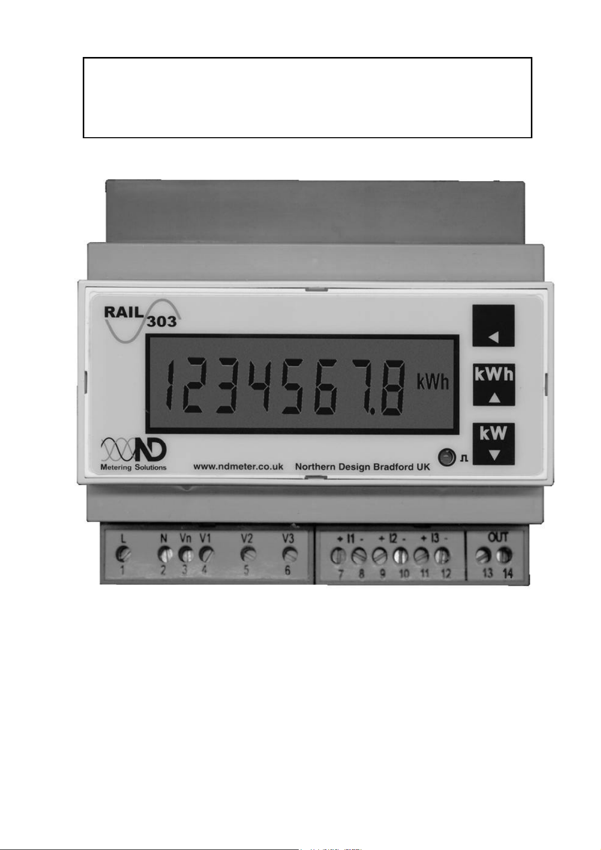
Model :PowerRail 303
Voltage :400/230 V 3 Phase, 3 or 4 wire
Current :5A from external CTs
Isolated Pulse Output :Fitted
Document Attached:
Northern Design (Electronics) Ltd. PowerRail 303 Operating Guide (August 2007)
Additional Information:
EM3/CT/N Three Phase Electricity Meter Data Sheet, TA200701
Disposal:
WEEE Directive :
EM3/CT/N
At the end of their useful life the packaging,
and product should be disposed of by a suitable
Do not dispose of with normal household waste.
Do not burn.
recycling centre.
1EM3/CT/N Installation Instructions TG200702 Issue 1/C 07/01/2008
Page 2

EM3/CT/N Installation Instructions
Please send any comments on this or any other Trend technical publication to techpubs@trendcontrols.com
Manufactured for and on behalf of the Environmental and Combustion Controls Division of Honeywell Technologies Sàrl, Ecublens, Route du
Bois 37,Switzerland by its Authorized Representative, Trend Control Systems Limited.
©Trend Control Systems Limited 2007. Trend Control Systems Limited reserves the right to revise this publication from time to time and make
changes to the content hereof without obligation to notify any person of such revisions or changes.
Trend Control Systems Limited
P.O. Box 34, Horsham, West Sussex, RH12 2YF, UK. Tel:+44 (0)1403 211888 Fax:+44 (0)1403 241608 www.trend-controls.com
Trend Control Systems USA
6670 185th Avenue NE, Redmond, Washington 98052, USA. Tel: (425)897-3900, Fax: (425)869-8445 www.trend-controls.com
2 EM3/CT/N Installation Instructions TG200702 Issue 1/C 07/01/2008
Page 3
PowerRail 303
Operating Guide August 2007
Copyright Northern Design Bradford UK 2007
Page 4

Safety
1 Safety
This instruction manual gives details of safe installation and operation of the PowerRail 303
electricity meter. Safety may be impaired if the instructions are not followed. Labels on each
meter give details of equipment ratings for safe operation. Take time to examine all labels before
commencing installation. Safety symbols on the meter have specific meanings.
Refer To User Manual Risk of Electric Shock
WARNING
The meter contains no user serviceable parts. Installation and
commissioning should only be carried out by qualified personnel
Further information is available at http://www.ndmeter.co.uk.
PowerRail303 Page 2
Page 5

Operation
2 Operation
2.1 Energy Displays
2.2 Total kWh Register
This default display presented on power up shows total kWh on an 8-digit accumulating register.
Register scaling is determined by user programmed CT and/or PT constants. On standard
PowerRail meters this register may not be reset.
2.3 KWh Count Register
The kWh Count display is a 7-digit resetable accumulating energy register. This acts in a similar
manner to the “Trip” display on a vehicle odometer.
• Press the key to select Total kWh or kWh Count display pages. The kWh Count
display remains visible for 1 minute before the unit reverts to Total kWh mode.
• Press and hold the and keys for approximately 5 seconds to reset the kWh Count
register to zero.
kWh
1234567.8
Total kWh Register
kWh
1234567.8
kWh Count Register
Scaling of the energy registers is set by the nominal input currents and voltages and remains
constant during normal operation of the meter.
Energy registers will accumulate from zero to 99999999, and then restart from zero.
If no keys are pressed, the meter will automatically revert to the Total kWh Register display after
60 seconds.
Both energy registers are stored in non-volatile memory during power loss to the meter.
Count
PowerRail303 Page 3
Page 6

Operation
2.4 Instantaneous kW Display
Press
kW
144.00
Instantaneous Power
2.4.1 REV CT
The instantaneous power display may show negative values indicating export power or incorrectly
wired inputs. REV CT will also be shown indicating that the most likely cause of the negative
reading is one or more current transformers fitted the wrong way round on the primary conductor.
2.5 kW Demand Display (Option)
Press
Demand
kW
100.00
kW Demand
KW demand is only available on meters factory fitted with this option. If the user sets a demand
period of N minutes (eg 30 minutes) the display will be updated every N seconds (eg every 30
seconds). The display shows the average of all kW readings taken over the most recent demand
period (eg average over 30 minutes). This average kW parameter is commonly known as kW
Demand.
Press
Pk Demand
kW
150.00
Peak kW Demand
Peak KW demand is only available on meters factory fitted with the demand option. The display
shows the largest value of kW demand recorded since the user last reset it. The peak kW
Demand value is stored during power loss to the meter.
2.5.1 Resetting Peak kW Demand
To reset Peak kW Demand, press and , for approximately 2 seconds, while displaying
Peak kW Demand.
PowerRail303 Page 4
Page 7

Operation
2.6 Setup Display Menu
Each meter is configured to operate in a specific system. The meter settings may be displayed on
the LCD in the Setup Display Menu.
Hold for 5 Seconds.
CT 200
Current Transformer Primary
The CT value should match the Nominal Primary rating of the current transformers fitted with the
meter.
Press .
Un 400
Nominal Line-Line Voltage (or PT Primary)
If no external potential transformer (PT) is fitted Un is the Rated Nominal Line-Line Voltage as
detailed on the meter label.
If a PT is fitted, its secondary voltage should match the Rated Nominal Line-Line Voltage of the
meter, Un is then programmed as the Nominal Rated Primary Voltage of the PT.
Press .
kWh
PLr 0.1
Output Pulse Rate
PLr indicates the amount of energy accumulated between each pulse output.
Press .
PLt 0.1
Pulse On Time
PLt indicates the length of time (in seconds) the output pulse contacts remain short circuit for each
pulse.
Press .
OPt Is a code indicating which factory fit options are supplied on an individual meter. This
information may be requested when contacting technical support.
PowerRail303 Page 5
OPt 1110
Options Fitted
Page 8

Operation
Press .
Demand
PER 30
kW Demand Period in Minutes
The kW demand period, in minutes, is only displayed on meters supplied with this factory fitted
option.
Press .
br 9600
Serial Communication Baud Rate
The baud rate is only displayed on meters supplied with the Modbus serial communication factory
fitted option.
Press .
Addr 1
Modbus Address
The Modbus address is only displayed on meters supplied with the Modbus serial communication
factory fitted option.
2.7 Pulse Output
An isolated pulse output is provided for connection to external systems such as Building Energy
Management Systems (BEMS), data loggers, remote counters etc.
A single pulse occurs for each unit of energy on the display (eg 1 pulse per 0.1kWh). The pulse
rate (amount of energy associated with each pulse) and pulse length may be set to suit the
external system.
2.7.1 Pulse LED
A green LED on the front panel of the instrument pulses ON during each output pulse.
Pulse Output Indicator
PowerRail303 Page 6
Page 9

Programming
3 Programming
3.1 Programming Menu
To enter programming mode: Hold and together for 5 Seconds.
The first programmable parameter, CT Primary, is displayed.
3.1.1 CT Primary Programming
Setup
CT 200
This should be set to match the nominal primary current rating, in Amps, of the external current
transformers (CTs) fitted to the meter. The CT secondaries must match the nominal input rating of
the meter (5A on standard meters).
Press the up key or down key to select CT values from a table of standard primary
currents.
Press when the desired value is set to move to the next parameter.
For primary currents not found in the standard table use fine adjust.
To enter/exit Fine Adjust mode, press and together for two seconds.
3.1.2 Nominal Primary Current Programming
Setup
CTf 190
Press the up key or down key to increase/decrease the CT primary setting in steps of
10A.
Press when the desired value is set to move to the next parameter.
3.1.3 Nominal Voltage Programming
Setup
Un 400
If no external Potential Transformer (PT) is fitted this is must be set to match the nominal line-line
voltage (Un) of the meter as detailed on its rating label.
If an external PT is fitted this should be set to match the PT nominal primary line-line voltage rating,
in volts. The PT secondary must match the nominal input rating of the meter (eg 110V L-L).
Press the up key or down key to select values from a table of standard PT primaries.
Press when the desired value is set to move to the next parameter.
PowerRail303 Page 7
Page 10

Programming
For PT primaries not found in the standard table use fine adjust.
To enter/exit Fine Adjust mode, press and together for two seconds.
Setup
Unf 410
Press the up key or down key to increase/decrease the PT setting in steps of 10V.
Press when the desired value is set to move to the next parameter.
3.1.5 Pulse Output Rate Programming
Setup
kWh
Plr 0.1
This sets the amount of energy measured between each pulse output. The scaling is dependant
on the display scaling and therefore on the CT and PT programming.
Press or to select pulse rates from a table.
Press when the desired value is set to move to the next parameter.
3.1.6 Pulse Output Length Programming
Setup
PlT 0.1
This sets the length, in seconds, of each pulse.
Press or to select pulse lengths (in seconds) from a table.
Press when the desired value is set to move to the next parameter.
3.1.7 Pulse Output Testing
Setup
Pto 9999
The pulse test facility allows the pulse output hardware and external system connections to be
commissioned without a measured load. The LCD shows Pto (off) and Ptr (run) and the number
of test pulses output. The test pulse rate is set automatically dependant on the programmed pulse
length (maximum 0.5Hz).
Press to start/stop the test pulses.
Press and together to stop the test pulses and simultaneously reset the test counter.
Press when the test is complete to move to the next parameter.
PowerRail303 Page 8
Page 11

Programming
3.1.8 KW Demand Period Programming
Demand Setup
PEr 30
This sets the time, in minutes, over which kW Demand measurements are averaged. This is
sometimes referred to as the sliding window or rolling average period.
Press or to increase/decrease the kW Demand period.
Press when the desired value is set to move to the next parameter.
3.1.9 Baud Rate Programming
Setup
br 9600
This sets the Baud Rate of the serial communications if the Modbus option is fitted at the factory.
Press or to select the desired baud rate from a table
Press when the desired value is set to move to the next parameter.
3.1.10 Modbus ID Programming
Setup
Addr 247
This sets the meters unique communications network ID (Modbus address) if the Modbus option is
fitted at the factory.
Press or to increase/decrease the value.
Press when the desired value is set to complete programming.
Setup
Storing
The programmed values are saved to non-volatile memory which is secure in the event of a loss of
auxiliary power to the meter.
PowerRail303 Page 9
Page 12

Display Scaling
4 Display Scaling
The units, Wh, kWh or MWh and the position of the decimal point for the energy/power displays
are automatically set dependant on the Ct and Un settings for the meter.
The nominal 3-phase input for the meter is defined as:
Wnom = 1.732 x Un x Ct
The display pages are scaled as follows:
Wnom
< 243 W 0.1W 0.001
< 2.43 kW 0.1W 0.001
< 24.3 kW 0.001 kW 0.01 kWh
< 243 kW 0.01 kW 0.1
< 2.43 MW 0.1 kW 1 kWh
< 24.3 MW 1 kW 0.01 MWh
< 243 MW 0.01 MW 0.1 MWh
> 243 MW 0.1 MW 1 MWh
kW
Resolution
kWh
Resolution
kWh
kWh
kWh
PowerRail303 Page 10
Page 13

Com
m
issioning
5 Commissioning
5.1 Standard Connections
3-Phase 3 or 4-Wire (*Optional Neutral)
PowerRail303 Page 11
3-Phase 3-Wire
Page 14

Com
m
issioning
HV Systems Using PTs
Single Phase
PowerRail303 Page 12
Page 15

Com
m
issioning
5.2 Pulse Output Connection
The pulse output takes the form of an isolated volt free normally open contact pair.
The contacts are isolated from all other circuits (2.5kV / 1 minute).
The pulse can be used as an input to a remote counter, pulse logger, building energy management
system etc.
5.3 Rail Mounting
The Power Rail 303 enclosure conforms to DIN 43880, 6 Modules wide. The unit is therefore
compatible with a number of standard DIN distribution systems with 45mm cut-outs. The Power
Rail 303 should be mounted on a 35mm, symmetric DIN rail of minimum length 106mm.
PowerRail303 Page 13
Page 16

Specification
6 Specification
Aux Mains
Input Voltage
Input Currents
Accuracy
LCD Display
Pulse Output
Nominal 230Vac ±15%, 45-65Hz, 1W max.
Optional 115Vac ±15%.
Un 400V Line-Line. Range 20%-120% Un
Burden 0.1VA / Phase. Overload 2xUn
Continuous.
Other nominal voltages are available to order.
Nominal Ib = 5A. Range 0.2%-120% Ib
Burden 0.1VA / Phase. Overload 20xIb (1 sec)
Isolation 2.5kV (1 minute)
Optional Ib = 1A
KWh: Class 1.
EN62053-21 & BS8431 (2% - 120% Nominal
Load)
KW: 1% Rdg (5% - 120% Nominal Load)
Green Backlit LCD 8 Digits h=9mm + Legends.
kWh Memory 10 years without power.
Normally open volt free contacts
1 pulse per energy increment.
Pulse rate and length selectable.
Contacts: 100V ac/dc, 100mA, 5W max
Isolation 2.5kV for 1 minute.
Environment
Other
Operate -10C > T < 65C. RH < 75% Non
Condensing
Storage -25C > T < 75C
Size: 106 x 90 x 58mm
Cut out: 106 x 45mm
Case: Noryl UL94 V-0 Self Extinguishing
Terminals: Rising Cage 4.0mm2
Weight: Approx 250g
PowerRail303 Page 14
 Loading...