

Page 1
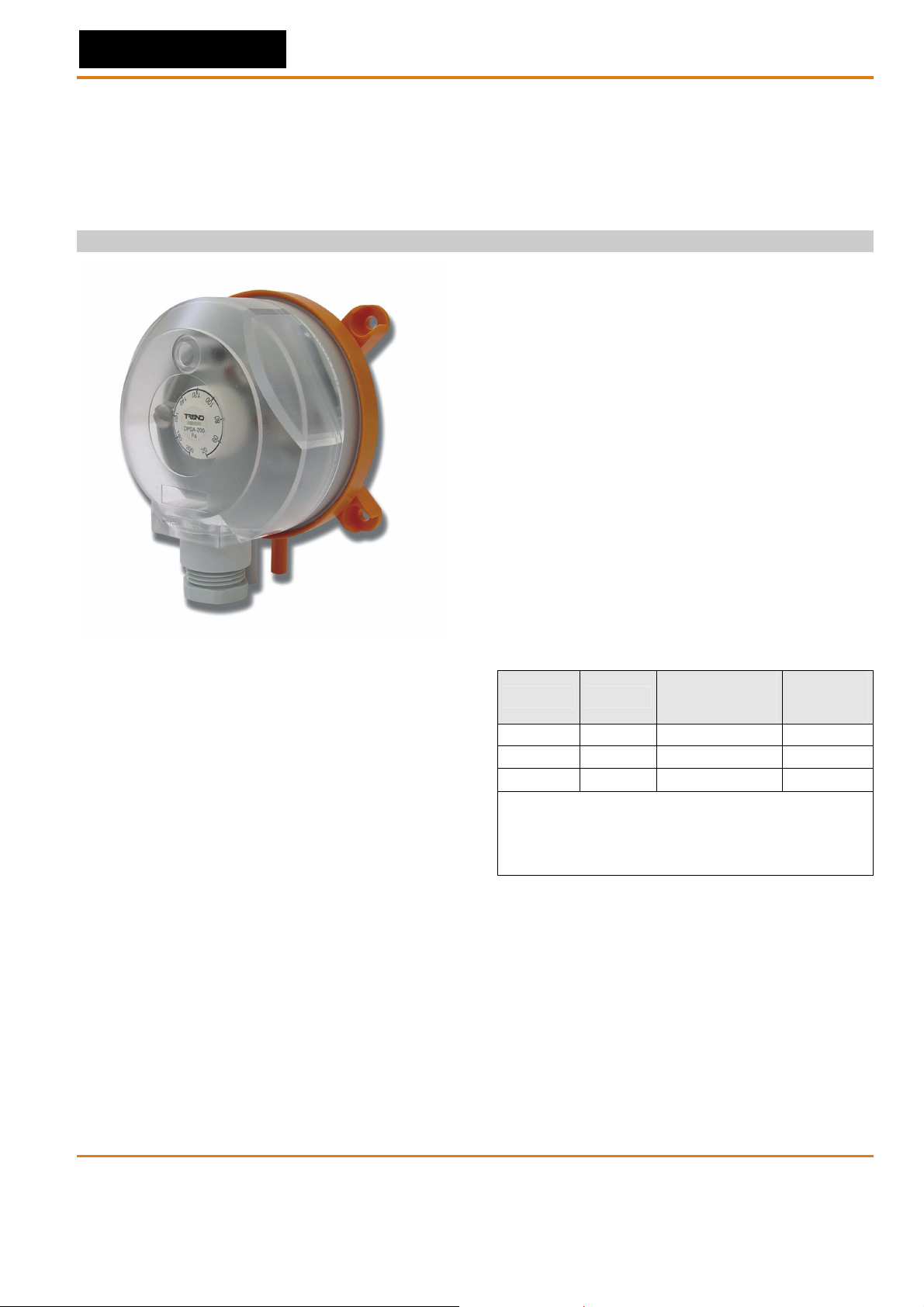
DPSA
DIFFERENTIAL PRESSURE SWITCHES
FOR AIR CONDITIONING / VENTILATION, USER-ADJUSTABLE
PRODUCT DATA AND INSTALLATION INSTRUCTIONS
TECHNICAL SPECIFICATIONS
Max. operating pressure 5000 Pa
Pressure media air, non-flammable gases, and
non-aggressive gases
Pressure connections two plastic tubes, outside
diameter: 6.0 mm (0.24”)
Switching capacity 1.5 A, (0.4) /250 Vac
Electrical connections screw terminals or AMP
connectors, 6.3 x 0.8,
DIN 46244
Conduit entry M20x1.5
Protection class IP 54
Mounting lugs integrated in bottom housing
(alternative: mounting angles)
Medium/ambient temp. -20...+85 °C (-4…+185 °F)
Storage temperature -40...+85 °C (-40…+185 °F)
Membrane material silicone
APPLICATION
Differential pressure switches e.g. for monitoring filter, fan,
fire damper, or air flow status of air handling systems.
BENEFITS
• Switching-point easily adjustable with scale in Pascal;
• Direction of M20x1.5 conduit entry can be rotated in
steps of 120°;
• Only one screw needed for housing cover.
APPROVALS
• CE approval according to low-voltage directive EEC
73/23;
• Switch according to VDE 0630;
• EC Gas Appliance Directive 90/396/EEC according to
DIN EN 1854 (Nov. 01, 1997)
CONTENTS OF DELIVERY
The delivery includes (in the case of individual packages)
the following parts:
• 1 DPSA Differential Pressure Switch
• 1 Data Sheet with installation information
• 1 duct kit, consisting of:
- 2 m (2 yds 6”) of hosing
- 2 joining pipes with four screws
OPERATING RANGES
adjustment range
type US code
DPSA 200 882001720 20...200 (Pa) 10 (Pa)
DPSA 400 882001730 40...400 (Pa) 20 (Pa)
DPSA 1000 882001740 200...1000 (Pa) 100 (Pa)
*The trip pressure refers to vertical mounting. In case of
horizontal mounting (with the cover pointing upwards), the
range values increase by 20 Pa (i.e. a setting of 40 Pa will
switch at 60 Pa). The unit should not be mounted face
down.
for upper trip
pressure*
switching
difference
(hysteresis)
DIMENSIONS
See "Mounting/Einbau/Montage" on page 4.
DPSA Data Sheet TA200878INT Issue 1/C 30/07/07 1
MU0B-0073GE51 R0707
Page 2
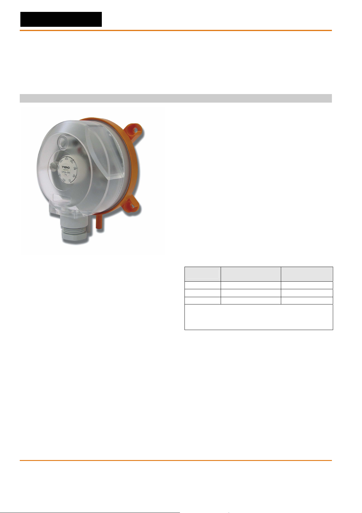
DPSA
DIFFERENZDRUCKSCHALTER
FÜR KLIMA- UND LÜFTUNGSANWENDUNGEN
PRODUKTINFORMATION UND MONTAGEANLEITUNG
TECHNISCHE DATEN
Max. Betriebsdruck 5000 Pa
Druckmedien Luft, nichtbrennbare Gase
sowie nichtaggressive Gase
Druckanschlüsse zwei Kunststoffstutzen mit
6,0 mm Außendurchmesser
Schaltleistung 1,5 A, (0,4) / 250 Vac
Elektrische Schraubklemmen oder AMP-
Anschlüsse Flachstecker, 6.3 x 0.8,DIN 46244
Kabeldurchführung M20x1.5
Schutzart IP 54
Befestigungsstutzen im Gehäuse integriert,
alternativ Befestigungswinkel
Umgebungs-/ -20...+85 °C
Mediumstemperatur
Lagertemperatur -40...+85 °C
Membranmaterial Silikon
ANWENDUNGEN
Differenzdruckschalter für Filter-, Ventilator- oder Luftströmungsüberwachung bei Klima- und Lüftungsanlagen.
VORTEILE
• Leicht verstellbare Schaltpunkte, mit Skala in Pa;
• Ausrichtung der M20x1.5 Kabeldurchführung in
Schritten von 120° leicht verstellbar
• Gehäusedeckel benötigt nur eine Schraube.
ZULASSUNGEN
• CE-Zulassung entsprechend Niederspannungs-
Richtlinie EEC 73/23;
• Schalter gebaut nach VDE 0630;
• EG-Gasgeräterichtlinie 90/396/EWG nach DIN EN
1854 (vom 01.11.1997)
LIEFERUMFANG
Die Lieferung beinhaltet (bei Einzelverpackung) Folgendes:
• 1 DPSA Differenzdruckschalter
• 1 Datenblatt mit Montagehinweisen
• 1 Zubehörkit, bestehend aus:
- 2 m Schlauch
- 2 Anschlußstutzen mit vier Befestigungsschrauben
BETRIEBSBEREICHE
Type
DPSA 200 20...200 (Pa) 10 (Pa)
DPSA 400 40...400 (Pa) 20 (Pa)
DPSA 1000 200...1000 (Pa) 100 (Pa)
*Die Druckangaben beziehen sich auf eine vertikale
Einbaulage. Bei waagrechter Montage erhöhen sich die
Werte um 20 Pa (z.B. bei 40 Pa auf 60 Pa). Das Gerät darf
nicht mit dem Gehäuse nach unten eingebaut werden.
Einstellbereich für
oberen Schaltdruck*
Konstante
Schaltdifferenz
ABMESSUNGEN
Siehe "Mounting/Einbau/Montage" auf Seite 4.
2 DPSA Data Sheet TA200878INT Issue 1C 30/07/07
MU0B-0073GE51 R0707
Page 3

POUR LE CONDITIONNEMENT DE L’AIR ET LA VENTILATION
DONNEES SUR LE PRODUIT ET INSTRUCTIONS DE MONTAGE
APPLICATION
Pressostat différentiel e.g. pour la surveillance de filtres,
ventilateurs ou clapet coupe feu dans des systèmes de
traitement de l’air ou de conditionnement.
AVANTAGES
• Points de commutation facilement ajustable, avec échelle
en Pa;
• Le connecteur M20x1.5 est orientable dans un rayon de
120°
• Le couvercle du boîtier ne necessite qu’une seule vis de
fixation.
CERTIFICATION
• Certification CE selon les dir. de tension basse EEC 73/23.
• Commutateur construit selon VDE 0630.
• Norme Europeenne apparell gaz 90/396/EEC suivant DIN
EN 1854 (Nov. 01, 1997).
CONTENU DE L'EMBALLAGE
L'emballage contient:
• 1 Pressostat différentiel DPSA
• 1 notice technique avec instruction du montage
• 1 kit contenant:
- 2 m de tuyaux
- 2 supports de connection avec 4 vis .
DPSA
PRESSOSTAT DIFFERENTIEL
SPECIFICATIONS TECHNIQUES
Pression Max. 5000 Pa
Média de pression Air, gas non-inflammables et
gas non-aggressifs
Contacts de pression Deux tubes avec
6,0 mm de diamètre extérieur
Capacité commutateur 1.5 A, (0.4) / 250 Vac
Raccordement Connecteurs à vis ou AMP,
électriques 6.3 x 0.8, DIN 46244
Entrée de cables M20x1.5
Classe de protection IP 54
Kit de fixation intégré dans le boîtier,
Option: equerre de fixation
Température -20...+85 °C
d‘environment
Température de stockage -40...+85 °C
Matériel de membrane Silicone
PLAGE D’UTILISATION
Plage de réglage
Type
DPSA 200 20...200 (Pa) 10 (Pa)
DPSA 400 40...400 (Pa) 20 (Pa)
DPSA 1000 200...1000 (Pa) 100 (Pa)
*Valeurs données pour un montage vertical. Pour montage
horizontal (avec le couvercle pointé vers le haut) augmenter
les valeurs de 20 Pa (par exemple, pour une installation de
40Pa, vous devrez l’augmenter à 60Pa). Le produit ne devra
pas être monté la face en bas
pour pression
supérieure*
DIMENSIONS
Voir "Mounting/Einbau/Montage" page 4.
Plage fixe de
commutation
DPSA Data Sheet TA200878INT Issue 1/C 30/07/07 3
MU0B-0073GE51 R0707
Page 4

DPSA Data Sheet
MOUNTING/EINBAU/MONTAGE
57.5 mm
2.26“
25 mm
0.87”
8
.
5
0
m
.
33”
m
Ø
0
0
.
5
.1
mm
8
”
59 mm
2.32”
65 mm
2.6”
50 mm
1.97”
*
18 mm
0.71”
Ø6 mm, 0.24”
Ø6.5 mm, 0.26”
6.5
16 mm, 0.63”
25 mm, 0.98”
6
18 mm
0.73”
18.5
60
60 mm
2.36”
4 mm, 0.16”
0.13”
3.4 mm
16
25
1 2
2
4 X
3
1
3
3
1
2
P1 = higher pressure = höherer Druck = pression haute
P2 = lower pressure = niedrigerer Druck = pression basse
*Use two screws, only, for mounting lugs!
*Zur Befestigung nur zwei Schrauben verwenden!
* N'utiliser que deux vis pour le montage.
** Remove transport protection from P2!
** Transportkappe von P2 entfernen!
** Enlever le couvercle de transport de P2.
DISPOSAL
4
P
-
+
NOTE: Do not install upside down with trip pressures of less
than 50 Pa!
HINWEIS:
Bei einem Schaltdruck von weniger als 50 Pa darf das
Gerät nicht über Kopf montiert werden!
NOTICE:
Ne pas installer à l'envers si la pression de commutation
est moins que 50 Pa!
E At the end of their useful life the packaging and product
should be disposed of via a suitable recycling centre. Do not
dispose of with normal household w aste. Do not burn.
DK Bortskaffelse af emballage og produkt skal foregå via et
genbrugscenter. Må ikke bortskaffes sammen med normal
husholdningsaffald. Må ikke brændes.
ES Al final de su vida útil, la cubierta y el equips deben ser
depositados en un centro de reciclaje apropiado. No se debe
desechar con los residuos normales. No qu emar.
F À la fin de leur vie utile l'emballage et le produit devront être recyclé par
un centre approprié. Ne pas les mélanger ou les jeter avec les déchets
ménagers. Ne pas brûler.
N Etter utgått levetid skal emballasje og produk leveres til et egnet
gjenvinningsanlegg. Skal ikke kastes i vanlig hush oldningsavfall. Skal
ikke brennes.
NL Aan het einde van hun levensduur dienen de verpakkin en het product
door een daarvoor geschikt recyclingsbedrijf te worden verwijderd . N iet
bij het huishoudelijk afval voegen. Niet verbranden.
Fi Tuote tulee toimittaa asianmukaiseen kierrätyspisteeseen. Älä
laita tavallisen kotitalousjätteen joukkoon. Älä polta.
I Al termine del loro utilizzo, l'imballo e il prodotto dovrebbero
essere collocati in un centro di riciclo appropriato. Non
collocare in un normale centro di raccolta rifiutti. Non bruciare.
D A m Ende der Lebensdauer sollte das Geräte an ein
Entsorgungsunternehmen abgegeben werden. Geben Sie
die Teile nicht in den normalen Haushaltabfall! Verbrennen
Sie auf keinem Fall die Materialien!
Manufactured for and on behalf of the Environmental and Combustion Controls Division of Honeywell Technologies Sàrl, Ecublens, Route du Bois 37,Switzerland by its Authorized Representative.
Trend Control Systems Ltd reserves the right to revise this publication from time to time and make changes to the content hereof without obligation to
notify any person of such revisions or change s.
Trend Control Systems Lim ited P .O. B ox 34 Hors ham, West Su ssex, RH 12 2YF, U K. T el: + 44 (0) 1403 2118 88, Fax : +4 4 (0)1 403 24 1608 , www .tren d-control s.com
Trend Control Systems USA 6670 185th Avenue NE, Redmond, Washington 98052, USA. Tel: (425)897-3900, Fax: (425)869-8445 www.trend-controls.com
4 DPSA Data Sheet TA200878INT Issue 1/C 30/07/07
MU0B-0073GE51 R0707
 Loading...