

Page 1
Liquid Differential Pressure Sensor
Important: Retain these instructions
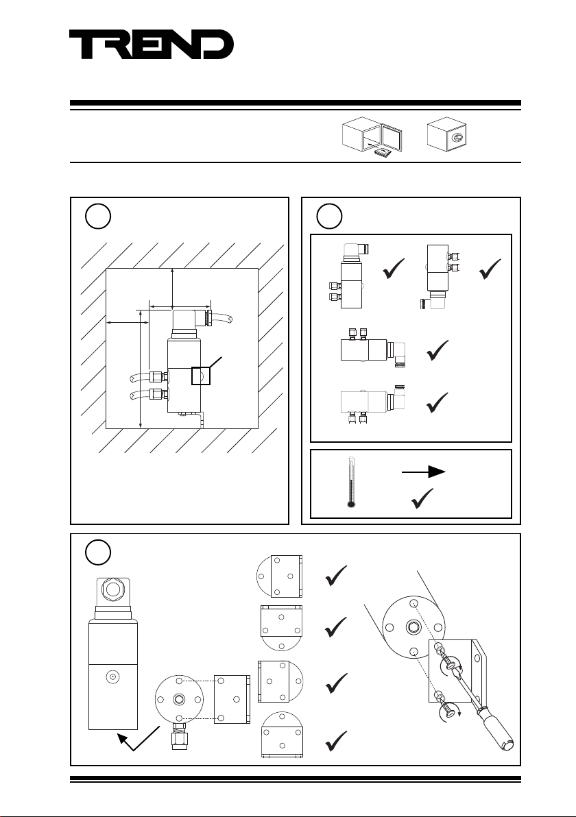
INSTALLATION
Installation Instructions
DPIL
Dimensions (mm)
1
100
145
Fix bracket
3
access for
connector screws
>20
77
not used
do not open
2
a
b
Requirements
-15 °C
+80 °C
DPIL Liquid Differential Pressure Sensor Installation Instructions TG200125 Issue 1/E 21/09/05
1
Page 2
DPIL Installation Instructions
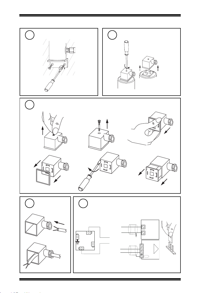
INSTALLATION (continued)
Fix to surface
4
Expose terminals
6
a
d
Remove connector
5
b
e
c
f
7
Insert cable
inside connector
Connect to controller
8
2
1
OUT
3
IN
+ supply
signal
IQ controller analogue input
channel linked for current (I)
IQ1xx/2xx
IN
24 V
IQ3
0 (0V)
N (IN)
+ (+24V)
I
2
DPIL Liquid Differential Pressure Sensor Installation Instructions TG200125 Issue 1/E 21/09/05
Page 3

Installation Instructions DPIL
INSTALLATION (continued)
Assemble and fit connector
9
ab
e
c
10
a
c
Requirements
P1 > P2
[P1 < P2]
-
P2
P1
+
d
b
Δ p < = Δ p max
-
P2
P1
+
P1
P2
xamP
ΔΔΔΔΔ
xamP
2Pdna1P1P2P
5.0/rab52rab3rab3
1/rab52rab5rab5
5.2/rab52rab21rab21
4/rab52rab21rab21
6/rab52rab21rab21
01/rab52rab02rab21
11
d
DPIL Liquid Differential Pressure Sensor Installation Instructions TG200125 Issue 1/E 21/09/05
Connect Pressure Points
a
e
b
f
c
Continued
3
Page 4

DPIL Installation Instructions
INSTALLATION (continued)
11
Connect Pressure Points (continued)
g
12
14
Configure IQ
I Q
IQ Configuration
Manual 90-1533
Test System
or
IQ
DISPOSAL
WEEE Directive :
At the end of their useful life the packaging
and product should be disposed of via a
Do not dispose of with normal household waste.
Do not burn.
suitable recycling centre.
h
ΔP = X
i
P2 -
P1+
not used
do not open
I Q
13
It is recommended to use SET (software tool) for
the setting of sensor type modules.
For all IQ2 series controllers with firmware version
2.1 or greater, or IQ3 series controllers, the
following unique sensor references should be used:
DPIL/0.5: Pressure I 0.5bar
DPIL/1:Pressure I 1bar
DPIL/2.5: Pressure I 2.5bar
DPIL/4:Pressure I 4bar
DPIL/6:Pressire I 6bar
DPIL/10: Pressure I 10bar
If not using SET, use the following tables for all
IQ2 series controllers of firmware version 2.1 or
greater or IQ3 controllers; for all other I Q Controllers
see Sensor Scaling Reference Card TB100521A
top menu
tYpe Sensor digI/p Driver Function loGic Loop
scHedule seQnc Analog digBit Knob sWitch Time
Zone Oss User addRess intcoN calarM reView Plot
calEndar
=?
Set up sensor type
Yx<CR>
TYPE x
=?
S=5 (characterise)
Y=, E=, U=, L=, P=, I
X <CR>
Range YEULPI1I2O1O
DPIL/0.5 2 2 0.5 0 2 4 20 0 0.5
DPIL/1 2210242001
DPIL/2.5 2 2 2.5 0 2 4 20 0 2.5
DPIL/4 2240242004
DPIL/6 2260242006
DPIL/10 2 2 10 0 2 4 20 0 10
(current)
+-
to I2=, O1 to O2=
1
2
Manufactured for and on behalf of the Environmental and Combustion Controls Division of Honeywell Technologies Sàrl, Ecublens, Route
du Bois 37,Switzerland by its Authorized Representative, Trend Control Systems Limited.
Trend Control Systems Limited reserves the right to revise this publication from time to time and make changes to the content hereof
without obligation to notify any person of such revisions or changes.
Trend Control Systems Limited
P.O. Box 34, Horsham, West Sussex, RH12 2YF, UK. Tel:+44 (0)1403 21888 Fax:+44 (0)1403 241608 www.trend-controls.com
4
DPIL Liquid Differential Pressure Sensor Installation Instructions TG200125 Issue 1/E 21/09/05
 Loading...