

Page 1
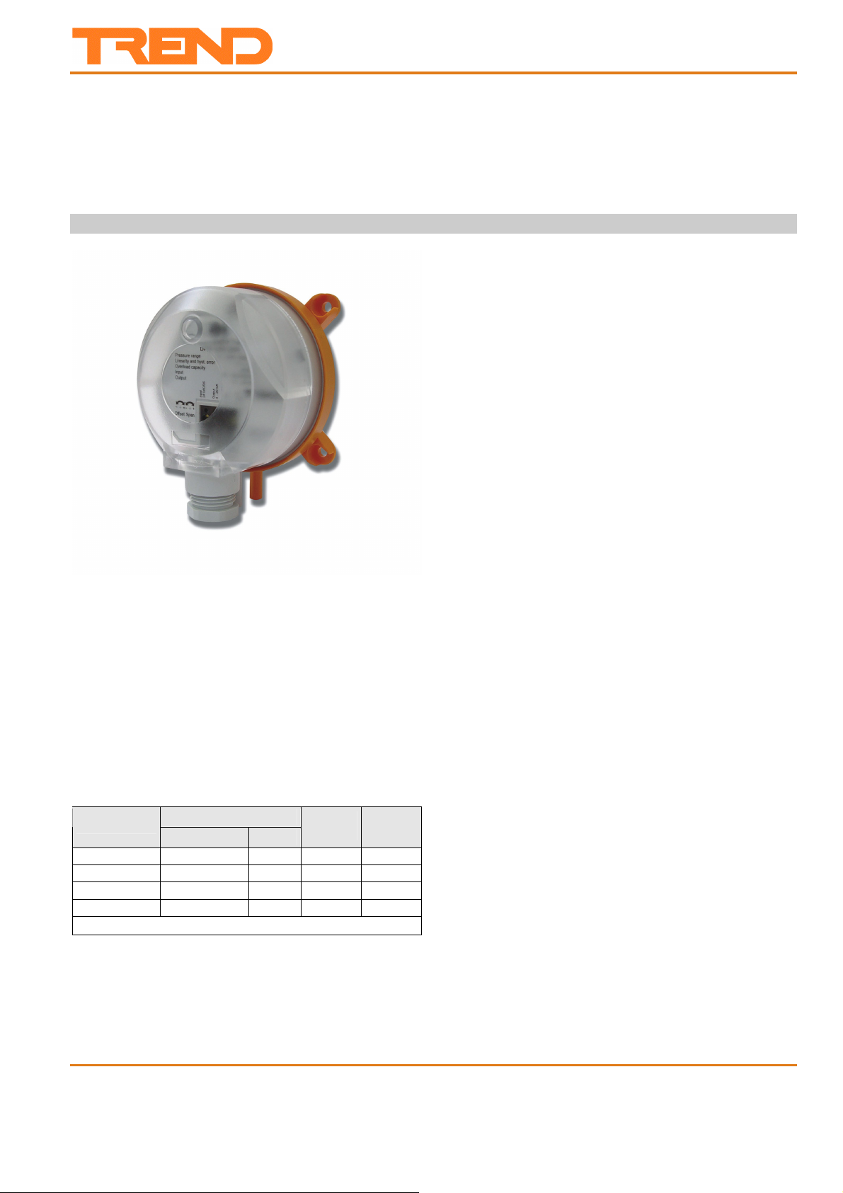
DPIA
2-WIRE DIFFERENTIAL PRESSURE TRANSMITTERS
CURRENT OUTPUT
SPECIFICATION DATA & MOUNTING INSTRUCTIONS
FEATURES
Monitoring gaseous, non-aggressive media
Piezo-resistive pressure transducer
Up to 40 kPa overload capacity
Rugged design; protection class IP54
Easy installation and wiring connection
Measurement range adjustable by jumper
Response time adjustable by jumper
Pushbutton zero adjustment
GENERAL
The differential pressure transmitters of the DPIA series are
used for measuring differential pressure, positive pressure,
and vacuum. The transmitters are suitable for:
air-conditioning,
building automation,
environmental protection,
valve and damper control,
filter and blower monitoring,
control of air flows.
Models
order no.
DPIA-100-250 0...100 Pa1) 0...250 Pa 20 kPa 40 kPa
DPIA-250-500 0...250 Pa1) 0...500 Pa 20 kPa 40 kPa
DPIA-500-1000 0...500 Pa1) 0...1 kPa 20 kPa 40 kPa
DPIA-1000-2500 0...1 kPa2) 0...2.5 kPa 40 kPa 70 kPa
1)
5% of FS; 2) 2.5% of FS
Supplied complete with connection kit comprising 2 m (2yds
7”) tubing, 2 connection tubes, and 4 screws
pressure range
1 2
overload
capacity
bursting
pressure
SPECIFICATION
Supply voltage 15 to 30 Vdc
Output signal 4...20 mA, two-wire
Maximum load 500 Ω
Pressure medium Air and non-aggressive
gases
Working temperature 0...50 °C
Linearity and hysteresis error 1.0% of FS
Temperature error at 0...50°C 1.0% of FS
Storage temperature -10 to 70 C (14 to 158 °F)
Humidity 0...95% rh, non-condensing
Long-term stability, typical
DPIA-100-250 to DPIA-500-1000
2.5% of FS per year
DPIA-1000-2500 1.5% of FS per year
Repetition accuracy 0.2% of FS
Position dependence 0.02% of FS per g
Response time 1s (switchable to 100 ms)
Process connection 6 mm (0.24”) hose pipe
Electrical connection Screw terminal block for wire
up to 1.5 mm² (16 AWG)
Housing material ABS and POM
Cable entry M20x1.5 (polyamide)
Protection class IP54 as per EN60529
EMC EN60770, EN61326
Weight approx. 130 g (4.57ozs)
1)
5.0% of FS
2)
2.5% of FS
DPIA Data Sheet TA200879 Issue 2, 3/03/2009 1
EN0B-0467GE51 R0707
Page 2
DPIA Data Sheet
FUNCTION
The DPIA Two-Wire Differential Pressure Transmitters are
equipped with an integrated piezo-resistive pressure
transducer designed so that the pressure to be measured is
applied to a thin membrane made of monosilicon, thus
deflecting it. The semiconductor resistors on the membrane
detect this mechanical deflection and generate an electrical
output signal. The arrangement of the resistors
simultaneously compensates for the temperature response.
The signal of the pressure transducer is converted into the
output signal by high-gain operation amplifiers.
The electrical output signal changes within the specified error
limits in proportion to the applied pressure.
NOTE: All DPIA Two-Wire Differential Pressure
Transmitters are factory pre-set to a response time
of 1s (slow).
NOTE: All DPIA Two-Wire Differential Pressure
Transmitters are factory pre-set to the lower
pressure range 1.
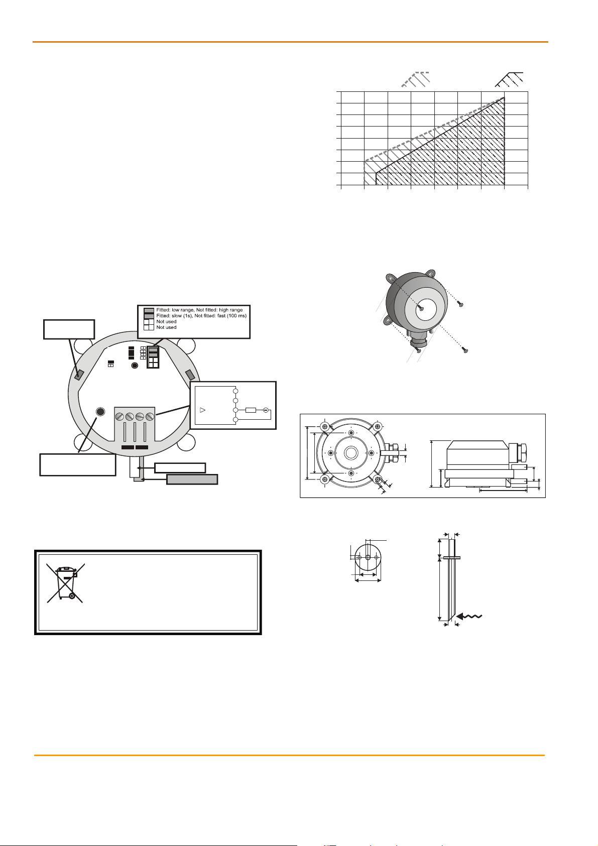
WIRING
storage positions
for pin plugs
Range
Response
Differential Pressure Transmitter
Pressure range 0 ... 100 Pa / 0 ... 250 Pa
Overload capacity 25 kPa
Linearity and hyst. Error <= +-1 % FS
Input 15 ... 30 V DC
Output 4 ... 20 mA
low
slow fast
Jumper yes
Jumper no
DPIA-100-250
Input
24 VDC
1
Default: links fitted
high
Output
4...20 mA
Do not
use
23
(Do not use)
4
(Do not use)
Do not
use
15 to 30 Vdc
4
...20 mA
4
3
load
2
1
permissible Vdc load permissible Vac load
800
600
400
200
resistive load (ohms)
0
201816
supply voltage (2-wire versions: Vdc, only)
Fig. 2. Permissible load vs. supply voltage
2422
MOUNTING
Fig. 3. Mounting
It is sufficient to use two screws to mount the unit.
DIMENSIONS
Ø6 (0.24”)
32302826
Zero Point Deviation:
Disconnect hoses and press
for 5 s to correct zero offset
P2 (low pressure)
P1 (high pressure)
50 (1.97”)
65.05 (2.56”)
Fig. 1. Wiring details
Fig. 4. Dimensions in mm (inches)
DISPOSAL
(0.13”)
WEEE Directive
At the end of their useful life the packa
and product should be disposed of by a
:
ging
suitable
recycling centre.
Do not dispose of with normal household waste.
Do not burn.
Please send any comments about this or any other Trend technical publication to techpubs@trendcontrols.com
© 2009 Honeywell
Technologies Sàrl, ECC Division. All rights rese
Honeywell Technologies Sàrl, Z.A. La Pièce, 16, 1180 Rolle, Sw
Trend Control Systems Limited reserves the right to revise this publi
person of such revisions or changes.
Trend Control Systems Limited
P.O. Box 34, Horsham, West Sussex, RH12 2YF, UK. Tel:+44
rved. Manufactured for and on behalf of the Environmental and Combustion Controls Division of
itzerland by its Authorized Representative.
cation from time to time and make changes to the content hereof without obligation to notify any
(0)1403 211888 Fax:+44 (0)1403 241608 www.trendcontrols.com
Trend Control Systems USA
6670 185th Avenue NE, Redmond, Washington 98052, USA. T
2
EN0B-0467GE51 R0707
el: (425)897-3900, Fax: (425)869-8445 www.trendcontrols.com
3.4 mm
16 mm, (0.63”)
25 mm, (0.98”)
Ø4.5 (0.18”)
8.5 (0.33”)
4 mm, (0.16”)
Ø6.5 mm, (0.26”)
57.5 (2.26”)
18 mm
60 mm
6.5
22 (0.86”)
59 (2.33”)
Ø6 mm, (0.24”)
(0.73”)
(2.36”)
Fig. 5 Connection tube
DPIA Data Sheet TA200879 Issue 2, 3/03/2009
18 (0.70”)
7.5 (0.29”)
 Loading...