

Page 1
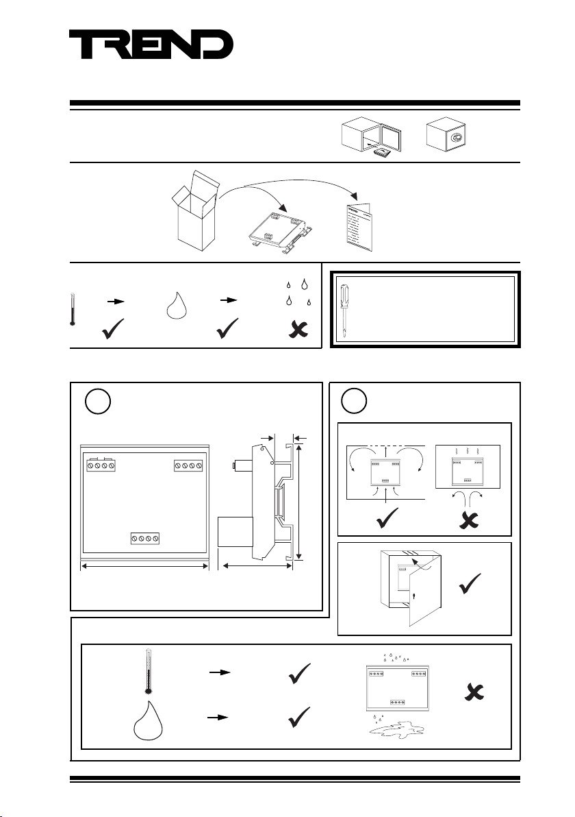
Important: Retain these instructions
OUT2
+
OUT1
IN2 0V 24V
-+-
IN1AC2 AC1
1 Unpacking
Installation Instructions
DPCM (24 Vac/dc)
Dual Phase Cut Module
DPCM (24 Vac/dc) Installation
Instruction TG200482
2 Storing
-10 °C
(14 °F)
+70 °C
(158 °F)
3 Installation
Dimensions
1
24Vac
-+-
OUT2+OUT1
91 mm (3.58”)
c
0 %RH
H O
2
IN2 0V 24V
IN1
-10 °C
(14 °F)
95 %RH
13 mm
(0.51”)
52 mm (2.05”)
+50 °C
(122 °F)
It is recommended that the installation
should comply with the HSE
Memorandum of Guidance on Electricity
at Work Regulations 1989.
2
a
82 mm (3.23”)
b
Requirements
IN2 0V24V
IN1AC2 AC1
+
-+OUT1
OUT2
0V24V
IN2
IN1AC2 AC1
-+-
OUT2+OUT1
IN2 0V24V
IN1AC2 AC1
+
-+OUT1
OUT2
0 %RH 90 %RH
H O
DPCM (24Vac/dc) Installation Instructions TG200482 Issue 3 07/07/08
2
1
Page 2
DPCM (24 Vac/dc) Installation Instructions
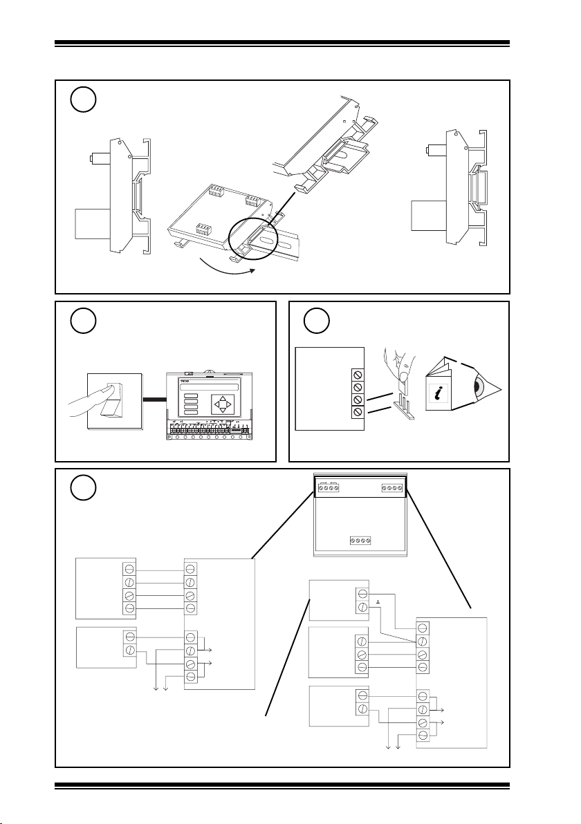
3 Installation (continued)
Mount on DIN rail
3
a
b
Switch off IQ
4
IQ
9 1 0
24V
0V
IN 1
IN 2
2 0
1 7
1 8
1 6
1 9
V
1 1
1 2
1 3
1 5
1 4
DPCM
24 Vac
D P
O K
LA N
TX R X
24 V
12 34 56 78 91 0
O
I
Wire module to controller
6
A
B
C
D
1
6 7 8
2 3 4 5
maximum current consumed from supply:
24 Vac 64 mA, 24 Vdc 30 mA
either using IQ 24 Vdc auxiliary supply
IQ
24V
0V
OUT 1
OUT 2
24 Vac
Supply
24 Vac
common
c
Ensure IQ Output channel(s)
5
are Analogue set to Voltage
V
IQ
24 V
0 V
OUT 1
OUT 2
2 analogue output channels
linked for voltage V
24Vac
-+-
OUT2+OUT1
or using external 24 Vac/dc supply
PSU
24 Vac/dc
IQ
0V
OUT 1
OUT 2
+~
-
IN2 0V 24V
IN1
V
IQ Controller
Installation
Instructions
24V
0V
IN 1
IN 2
DPCM
ac supply to next module
24 Vac
Supply
Note that external 24 V supply should be
isolated or earthed (grounded) to IQ earth
(ground),
ensure correct polarity
2
DPCM (24Vac/dc) Installation Instructions TG200482 Issue 3 07/07/08
24 Vac
common
24 Vac
ac supply to next module
Page 3

Installation Instructions DPCM (24Vac/dc)
OUT2+OUT1
IN2 0V24V
-+-
IN1
24Vac
OUT2+OUT1
IN2 0V 24V
-+-
IN1
24Vac
3 Installation (continued)
Wire module to controller (continued)
6
Using 24 Vac external supply for both control and output supplies
DPCM
24V
0V
IN 1
IN 2
24 Vac
Note that external 24 V supply
should be isolated or earthed
(grounded) to IQ earth (ground);
ensure correct polarity
IQ
0V
OUT 1
OUT 2
24 Vac
Supply
24 Vac
common
ac supply to next module
Ensure Power Supply to HVAC
7
Equipment is Switched off
O
I
HVAC Equipment
Power Supply
WARNING: The wires may be connected
to hazardous voltages.
Disconnect power before
attempting any wiring.
DPCM
Connect module to HVAC
8
equipment
OUT 1+
OUT 1OUT 2+
OUT 2-
HVAC Equipment
HVAC Equipment
Item 1
Item 2
CAUTION
No circuit protection is provided against output short circuits; if this occurs the circuit may be
damaged. The outputs must not be connected or disconnected when the DPCM is powered. The
output circuit must not contain any other switch circuit, such as manual override; if required,
these must be implemented either in the controller strategy, or in the 10 V signal. The outputs
should be connected only to their loads (i.e. kept isolated from earth or other supplies).
Close panel
9
0V24V
IN2
IN1AC2 AC1
-+-
OUT2+OUT1
10
Switch on IQ
O
I
IQ
D P
A
B
C
D
1
6 7 8
2 3 4 5
O K
1 7
2 0
1 8
1 6
1 9
LA N
TX R X
V
24 V
1 1
9 1 0
1 2
1 3
1 5
1 4
12 34 56 78 91 0
DPCM (24Vac/dc) Installation Instructions TG200482 Issue 3 07/07/08
3
Page 4

DPCM (24 Vac/dc) Installation Instructions
3 Installation (continued)
11
12
Switch on HVAC Equipment Power supply
Check operation
1
2345
4 Disposal
A
B
C
D
678
9101112
O
I
HVAC Equipment
Power Supply
IQ
DP
OK
17
20
18
16
19
LAN
TX RX
V
24V
13
15
14
12345678910
DPCM
0V 24V
IN1
IN2
OUT1
+
-+-
OUT2
24Vac
HVAC
Equipment
Item 1
HVAC
Equipment
Item 2
WEEE Directive :
At the end of their useful life the packaging
and product should be disposed of by a
Do not dispose of with normal household waste.
Do not burn.
Please send any comments about this or any other Trend technical publication to techpubs@trendcontrols.com
© 2008 Honeywell Technologies Sàrl, ECC Divison. All rights reserved. Manufactured for and on behalf of the Environmental and Combustion Controls
Division of Honeywell Technologies Sàrl, Ecublens, Route du Bois 37, Switzerland by its Authorized Representative, Trend Control Systems Ltd.
Trend Control Systems Limited reserves the right to revise this publication from time to time and make changes to the content hereof
without obligation to notify any person of such revisions or changes.
Trend Control Systems Limited
P.O. Box 34, Horsham, West Sussex, RH12 2YF, UK. Tel:+44 (0)1403 21888 Fax:+44 (0)1403 241608 www.trend-controls.com
Trend Control Systems USA
6670 185th Avenue NE, Redmond, Washington 98052, USA. Tel: (425)897-3900, Fax: (425)869-8445 www.trend-controls.com
4
suitable recycling centre.
DPCM (24Vac/dc) Installation Instructions TG200482 Issue 3 07/07/08
 Loading...