

Page 1

963 User Guide Issue 3
Page 2

Author: Technical Publications
Issue: 3
Date: 25/03/2008
Part Number: TC200635
Copyright: © 2008 Honeywell Technologies Sàrl, ECC Division. All rights reserved.
This manual contains proprietary information that is protected by copyright. No part of this manual may be
reproduced, transcribed, stored in a retrieval system, translated into any language or computer language, or
transmitted in any form whatsoever without the prior consent of the publisher.
Manufactured for and on behalf of the Environmental and Combustion Controls Division of Honeywell
Technologies Sàrl, Ecublens, Route du Bois 37, Switzerland by its Authorized Representative, Trend Control
Systems Limited.
For information contact:
Trend Control Systems Limited
P.O. Box 34
Horsham
W. Sussex
RH12 2YF
NOTICE: Trend Control Systems Limited makes no representations or warranties of any kind whatsoever with
respect to the contents hereof and specifically disclaims any implied warranties of merchantability or fitness for any
particular purpose. Trend Control Systems Limited shall not be liable for any errors contained herein or for
incidental or consequential damages in connection with the furnishing, performance or use of this material. Trend
Control Systems Limited reserves the right to revise this publication from time to time and make changes in the
content hereof without obligation to notify any person of such revisions or changes.
Windows, Windows XP Professional, Windows XP Home, Windows 2003, Windows 2003, and Windows Vista are
trademarks of Microsoft Corporation. BACnet is a trademark of ASHRAE.
Please send any comments on this or any other Trend technical publication to techpubs@trendcontrols.com
Page 3

Table of Contents
TABLE OF CONTENTS
1 ABOUT THIS MANUAL................................................................................................................................. 5
1.1 Conventions Used in this Manual ................................................................................................................ 5
1.2 Contacting Trend.......................................................................................................................................... 6
2 ABOUT 963 ....................................................................................................................................................... 7
2.1 The 963 Window.......................................................................................................................................... 7
2.1.1 Data Display .....................................................................................................................................9
2.1.2 Menu Bar ........................................................................................................................................ 19
2.1.3 Navigator ........................................................................................................................................19
2.1.4 Network Comms Status Lights ....................................................................................................... 24
2.1.5 Selection Buttons ............................................................................................................................24
2.1.6 Status Bar........................................................................................................................................ 24
2.2 The Information Centre Window ...............................................................................................................25
3 USING 963....................................................................................................................................................... 27
3.1 Basic Use.................................................................................................................................................... 27
3.1.1 Run 963........................................................................................................................................... 28
3.1.2 Log In.............................................................................................................................................. 28
3.1.3 Log Off ...........................................................................................................................................28
3.1.4 Close 963 ........................................................................................................................................ 29
3.2 Display a Schematic Page ..........................................................................................................................29
3.2.1 Zoom in and Out of a Schematic Page............................................................................................ 30
3.2.2 Print a Schematic Page....................................................................................................................30
3.3 Adjust Values............................................................................................................................................. 31
3.3.1 Adjust Knob Values........................................................................................................................ 31
3.3.2 Adjust Switches .............................................................................................................................. 32
3.3.3 Adjust a Module Parameter ............................................................................................................33
3.3.4 Relinquish Control of a BACnet Value .......................................................................................... 34
3.4 Alarms........................................................................................................................................................ 35
3.4.1 View Alarms................................................................................................................................... 35
3.4.2 Action Alarms................................................................................................................................. 38
3.4.3 Hide Alarm Panels.......................................................................................................................... 39
3.4.4 Mute an Alarm Panel ......................................................................................................................39
3.4.5 Reset the Count of SMS Alarms..................................................................................................... 40
3.4.6 Run a Manual Alarm Action........................................................................................................... 40
3.4.7 Print................................................................................................................................................. 40
3.5 Display Graphs........................................................................................................................................... 42
3.5.1 Display a Compact Graph............................................................................................................... 42
3.5.2 Display a Precision Graph ..............................................................................................................43
3.5.3 Display a Chart ...............................................................................................................................44
3.5.4 Load a Graph Definition ................................................................................................................. 44
3.5.5 Display the Graph Data................................................................................................................... 45
3.5.6 Zoom in and Out of a Graph........................................................................................................... 45
3.5.7 Formatting Graphs .......................................................................................................................... 46
3.5.8 Save a Graph Definition.................................................................................................................. 48
3.5.9 Print a Graph................................................................................................................................... 48
3.6 Occupation Times ...................................................................................................................................... 49
3.6.1 View Occupation Times .................................................................................................................49
3.6.2 Adjust Occupation Times ...............................................................................................................50
3.6.3 Printing ...........................................................................................................................................57
3.7 Record Data................................................................................................................................................ 58
3.7.1 Record a Graph Automatically .......................................................................................................58
3.7.2 Record a Graph Manually............................................................................................................... 59
3.7.3 Record a Schematic Page................................................................................................................ 61
3.8 Playback Recorded Data ............................................................................................................................ 62
3.8.1 Playback a Recorded Page.............................................................................................................. 63
3.9 Display the IQ System ...............................................................................................................................66
3.9.1 Print the Device Viewer.................................................................................................................. 67
3.10 Display Scheduled Events.......................................................................................................................... 67
3.10.1 Print the Scheduled Events ............................................................................................................. 68
3.11 Display IQ3 Web Pages............................................................................................................................. 68
963 User Guide TC200635 Issue 3 25/03/2008 3
Page 4

Table of Contents
3.12 Display HTML Pages ................................................................................................................................ 68
3.13 Display the Information Centre ................................................................................................................. 69
3.14 Send an SMS Message............................................................................................................................... 69
3.15 Layout the Window ................................................................................................................................... 70
3.15.1 Automatically Hide the Navigator.................................................................................................. 70
3.15.2 Collapse Message Boxes ................................................................................................................ 70
3.15.3 Hide Selection Buttons................................................................................................................... 70
3.15.4 Hide the Menu Bar ......................................................................................................................... 70
3.15.5 Hide the Status Bar......................................................................................................................... 70
3.15.6 Minimise Selection Buttons............................................................................................................ 71
3.15.7 Move the Navigator........................................................................................................................ 71
3.15.8 Reset the Display............................................................................................................................ 71
3.16 Manage Your User Account ...................................................................................................................... 71
3.16.1 Change Your Password .................................................................................................................. 72
3.17 Administer a 963 System........................................................................................................................... 73
3.17.1 Users............................................................................................................................................... 73
3.17.2 Data ................................................................................................................................................ 77
3.17.3 View an Audit Trail........................................................................................................................ 81
3.17.4 Clear the Print Buffer ..................................................................................................................... 81
3.18 Enter Configuration Mode on Pre IQ3 Controllers.................................................................................... 82
3.18.1 Print Text from a Configuration Session........................................................................................ 83
3.19 Control Scripts........................................................................................................................................... 83
3.20 Insert a List into an HTML File................................................................................................................. 84
3.21 Save a List to HTML................................................................................................................................. 84
3.22 Setup Exception Templates ....................................................................................................................... 85
3.22.1 Add a Special Day Template.......................................................................................................... 85
3.22.2 Add a Week Set Template.............................................................................................................. 85
3.22.3 Delete a Template........................................................................................................................... 87
3.22.4 Edit a Template............................................................................................................................... 87
3.22.5 Import Exception Templates .......................................................................................................... 87
3.22.6 Load Existing Times....................................................................................................................... 88
3.22.7 Load Times From a Controller....................................................................................................... 88
3.22.8 View Where Templates are Used ................................................................................................... 89
3.23 View Communications Information .......................................................................................................... 89
3.23.1 View Communications in the Communications Window .............................................................. 89
3.23.2 View Communications in the Remote Connection Window.......................................................... 89
3.23.3 View SMS Activity ........................................................................................................................ 90
3.24 View External Database Records............................................................................................................... 90
INDEX ....................................................................................................................................................................... 93
963 User Guide TC200635 Issue 3 25/03/2008 4
Page 5

About This Manual
1 ABOUT THIS MANUAL
This manual applies to 963 version 3.0 software. It provides a description of how to use the 963. It is intended for a
reader with no knowledge of the 963 who operates it on a daily basis. It is assumed that the system has already been
set up and engineered to suit user requirements, and the user is familiar with basic computer use, and has knowledge
of BMS. It is divided into several sections.
About 963
This section describes 963, and how it works.
The 963 Window
This section explains the different parts of the 963 Window.
Using 963
This section describes how to use 963 once it has been installed and engineered.
After having read and fully understood this manual the user will be familiar with the 963 Supervisor, the
environment in which it operates, making changes to HVAC equipment parameters, coping with incoming alarms,
and all other aspects of using the 963 on a day-to-day basis.
For details about using the 963 when accessing it from a web browser see the 963 Web User Guide (TC200631).
Other relevant documentation is:
Printable copy of this Help file in PDF format (963 User Guide)
963 Data Sheet (TA200636)
963 Web User Guide (TC200631)
Product Data Sheets
1.1 Conventions Used in this Manual
There are numerous items and instructions in this manual, the conventions below are designed to make it quick and
easy to find and understand the information.
! Menu commands are in bold type.
! Buttons, and options in dialogue box that you need to select are in bold type.
! The names of text boxes and dialogue boxes are in bold type.
! Key combinations that you should press appear in normal type. If joined with a plus sign (+), press and
hold the first key while you press the remaining one(s). For example CTRL+P indicates holding down the
control key while pressing P.
! Text you should enter is in Italic type.
963 User Guide TC200635 Issue 3 25/03/2008 5
Page 6

About This Manual
1.2 Contacting Trend
Head Office
Trend Control Systems Ltd
PO Box 34
Horsham
Sussex
RH12 2YF
England
Tel: +44 (0) 1403 211888
Fax: +44 (0) 1403 241608
Details of regional offices can be found on our Web site.
Internet
Our company web site (www.trend-controls.com) provides information about our products and us, or our support
web site (http://pnet.trend-controls.com).
Technical Support
Our support department provides technical support during normal office hours. Before contacting them ensure that
you have your Technical Support PIN number available, without this we will be unable to provide you with any
support.
Trend Control Systems Ltd.
Technical Support Department
PO Box 34
Horsham
Sussex
RH12 2YF
England
Tel: +44 (0) 1403 226600
Email: trendts@trendcontrols.com
Fax: +44 (0) 1403 226310
Technical Publications
Please send any comments on this or any other Trend technical publication to techpubs@trendcontrols.com
963 User Guide TC200635 Issue 3 25/03/2008 6
Page 7

About 963
2 ABOUT 963
Once engineered the 963 Supervisor provides the user with a system wide control panel with the facility to monitor
and change the Building Management System (BMS) ensuring that the HVAC equipment operates safely and
efficiently.
The use of colour graphics specially designed for the system displays this information in a simple and effective way.
Graphs and pages of text information can be used to supplement monitored information. A fast and efficient
communications network allows this information to be obtained from HVAC equipment that may scattered miles
apart in different buildings, on other sites, or even other countries.
It enables the user to monitor HVAC equipment/building services, and make changes to the way the building is
controlled using colour graphics displays. Fault reporting, analysis, and data recording features promote efficient
HVAC equipment operation and effective energy use.
The information and adjustments available to a user can be exactly tailored to that user’s needs. This means that an
operator is never presented with more data or options than he or she requires, thus eliminating a major source of
potential confusion. However, for those whose job function demands it, access can be provided to detailed
information on the BMS.
2.1 The 963 Window
The 963 Window consists of six areas:
Data Display
The Data Display is where the 963 displays the selected information. In the example above, a schematic page is
displayed, but information from other areas of 963 may also be displayed depending which button is selected, for
example the Alarm Viewer, web pages etc.
Menu Bar
The Menu Bar contains 963’s menus, which provide access to the application’s various features.
963 User Guide TC200635 Issue 3 25/03/2008 7
Page 8

About 963
Navigator
The Navigator appears on the left of the 963 Window, and provides a way of selecting the information that appears
in the Data Display. For example, if a schematic page is displayed the Navigator will enable the page that is
displayed to be selected, where as if the User Display is selected; it enables a particular user or workgroup to be
selected.
Network Comms Status Lights
The Network Comms Status Lights appear at the bottom of the 963 Window. They provide information about the
status of communications.
Selection Buttons
The Selection Buttons appear at the bottom of the Navigator. They provide access to the 963’s different displays.
Access to these buttons can be protected, preventing unauthorised users accessing the displays.
Status Bar
The Status Bar is located at the bottom of the 963 Window and provides information about the version of 963
running, and the name of the user that is currently logged on as well as the current date and time.
963 User Guide TC200635 Issue 3 25/03/2008 8
Page 9
About 963
2.1.1 Data Display
The Data Display is where 963 displays the information specified in the Navigator. The Selection Buttons determine the type of data displayed, and the selection made hat has been chosen. There are eight different type of display that can appear in the data display.
Alarm Viewer
Configuration Mode Display
Device Viewer
Web Browser Display
Event Scheduler Display
Diary Display
Schematic Page Display
User Display
2.1.1.1 Alarm Viewer
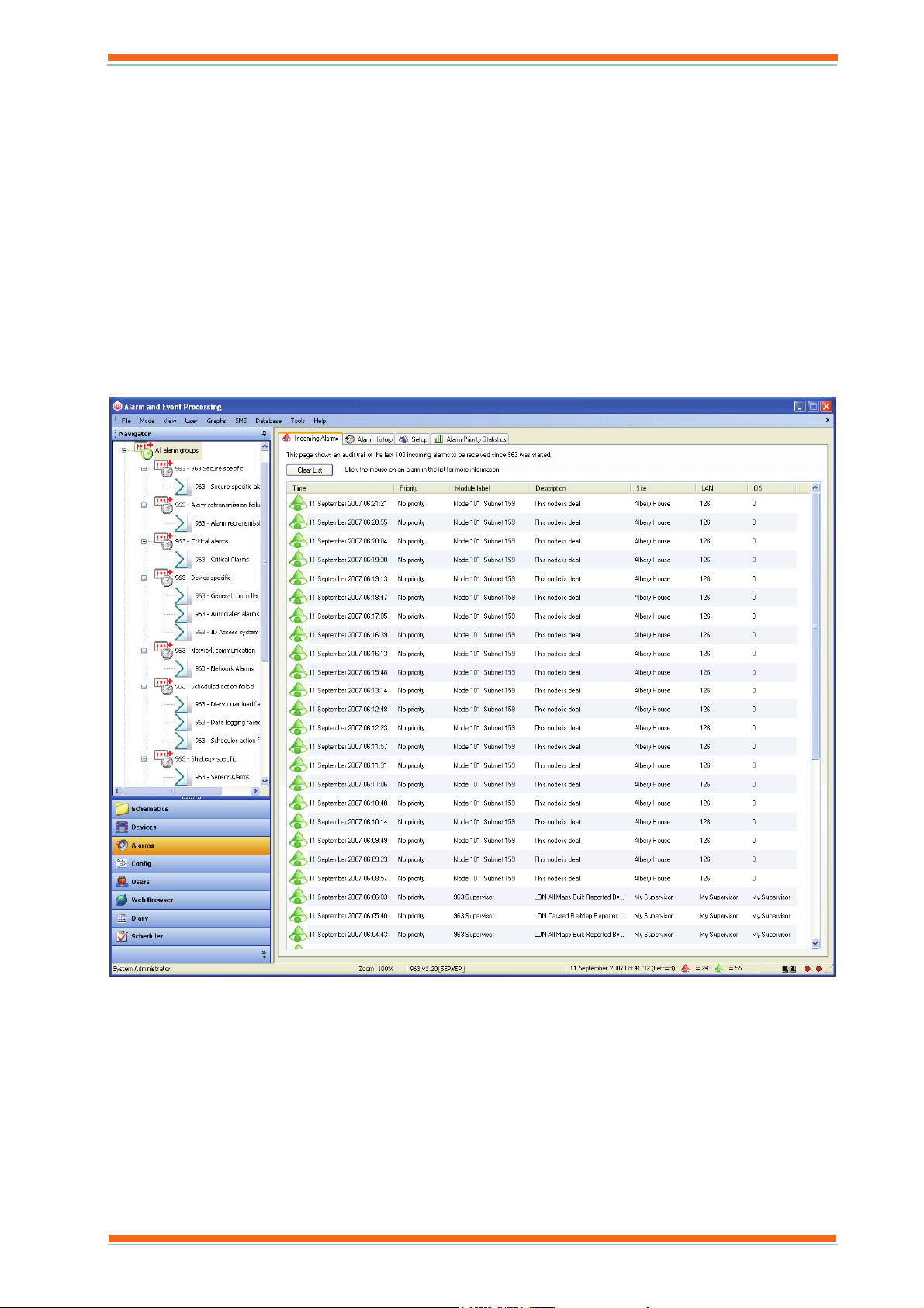
The Alarm Viewer, shown below, displays the alarms that have been received. These alarms can be filtered by type to reduce the amount of data displayed.
It has four tabs:
Alarm History
The Alarm History tab stores all the alarms after they have been processed, whether or not they have been
actioned by the user. The alarms can be viewed in Chronological View order or a Summary View.
The Summary View gives a count for each alarm type for each point, providing the following
information: The label of the module that generated the alarm, its priority, the device that sent the
alarm, a description of the alarm, and a count of how many alarm of that type have occurred.
The Chronological View displaysan alarm history sorted by time order, providing the following
information: The time the alarm occurred, its priority, the label of the module that generated the
alarm, a description of the alarm, the device that sent the alarm, and any text entered by the user
when it was acknowledged.
963 User Guide TC200635 Issue 3 25/03/2008 9
Page 10
About 963
Clicking any alarm gives a pop-up display containing details about the alarm. The alarms in both view are
determined by the currently selected group or filter in the Navigator. The list can be further filtered using a
drop-down list of standard options. The list is colour coded to indicate whether the alarm is current. Red
indicates that the alarm is current. Icons are used to indicate whether the alarm is a set alarm or a cleared
alarm. A red bell indicates a set alarm, and a green bell indicates a cleared alarm. If the alarm has been
actioned by the user, the bell will appear with a tick over it. The table below shows the different icons.
Icon Description
Alarm Priority Statistics
The Alarm Priority Statistics tab displays all the alarms grouped by priority in the form of a bar, or pie
chart.
Incoming alarms
The Incoming Alarms tab contains the last 100 alarms to be received as they arrive. The list is colour
coded to indicate whether the alarm is current. Red indicates that the alarm is current. Icons are used to
indicate whether the alarm is a set alarm or a cleared alarm. A red bell indicates a set alarm, and a green
bell indicates a cleared alarm. If the alarm has been actioned by the user, the bell will appear with a tick
over it. The table below shows the different icons.
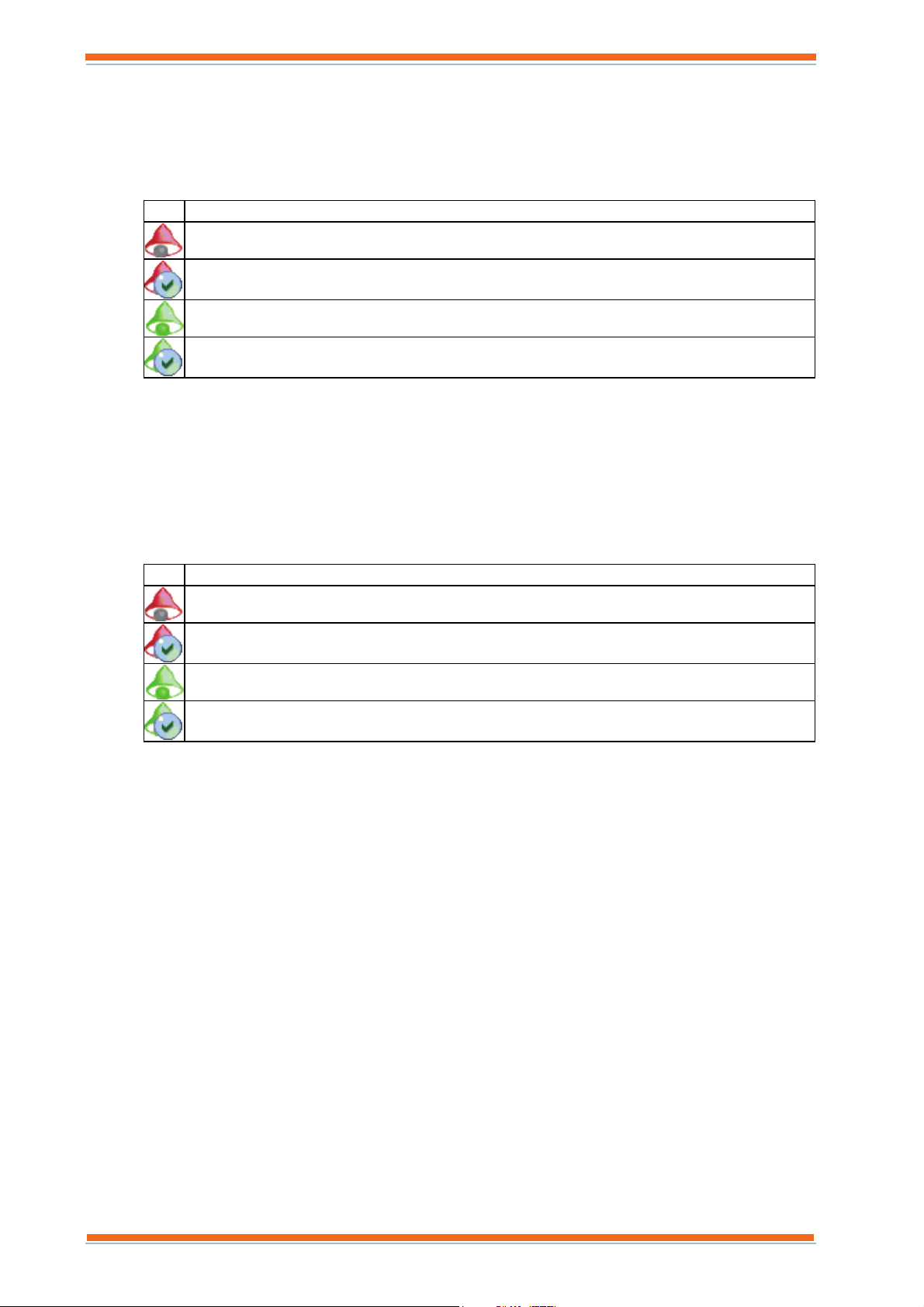
Set alarm that has not been actioned.
Set alarm that has been actioned.
Cleared alarm that has not been actioned.
Cleared alarm that has been actioned.
Icon Description
Set alarm that has not been actioned.
Set alarm that has been actioned.
Cleared alarm that has not been actioned.
Cleared alarm that has been actioned.
The list displays the time the alarm occurred, it priority, a description of the alarm, and the module label,
site, Lan, and device there generated the alarm. Clicking any alarm gives a pop-up display containing
details about the alarm
Set up
The Set up tab enables certain settings relating to alarm handling to be defined.
Access to this display can be restricted.
963 User Guide TC200635 Issue 3 25/03/2008 10
Page 11
About 963
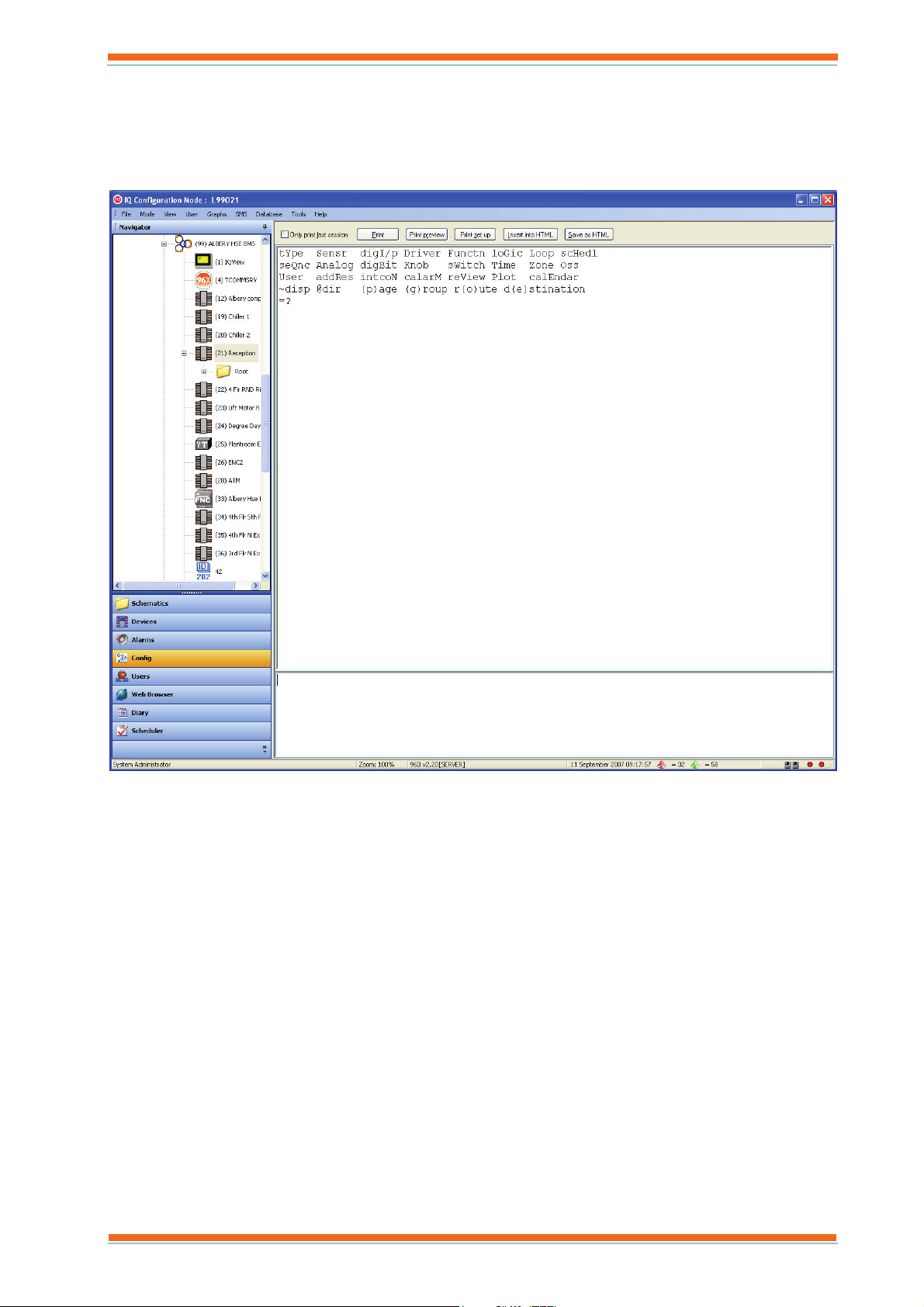
2.1.1.2 Configuration Mode Display
The Configuration Mode Display, shown below, displays the configuration mode on IQ system devices that support the feature. The required devices is selected from the Navigator which displays a tree view of the system to which 963 is connected,. Clicking a controller will cause it to enter configuration mode, and the configuration prompts displayed in the Data Display.
Once in this mode, simple adjustments can be made to the strategy. When in configuration mode, 963 is effectively
converted into a terminal, all the screen prompts originate from the controller, and all keyboard inputs are sent to the
controller when the ENTER key is pressed.
Access to this display can be restricted.
963 User Guide TC200635 Issue 3 25/03/2008 11
Page 12
About 963
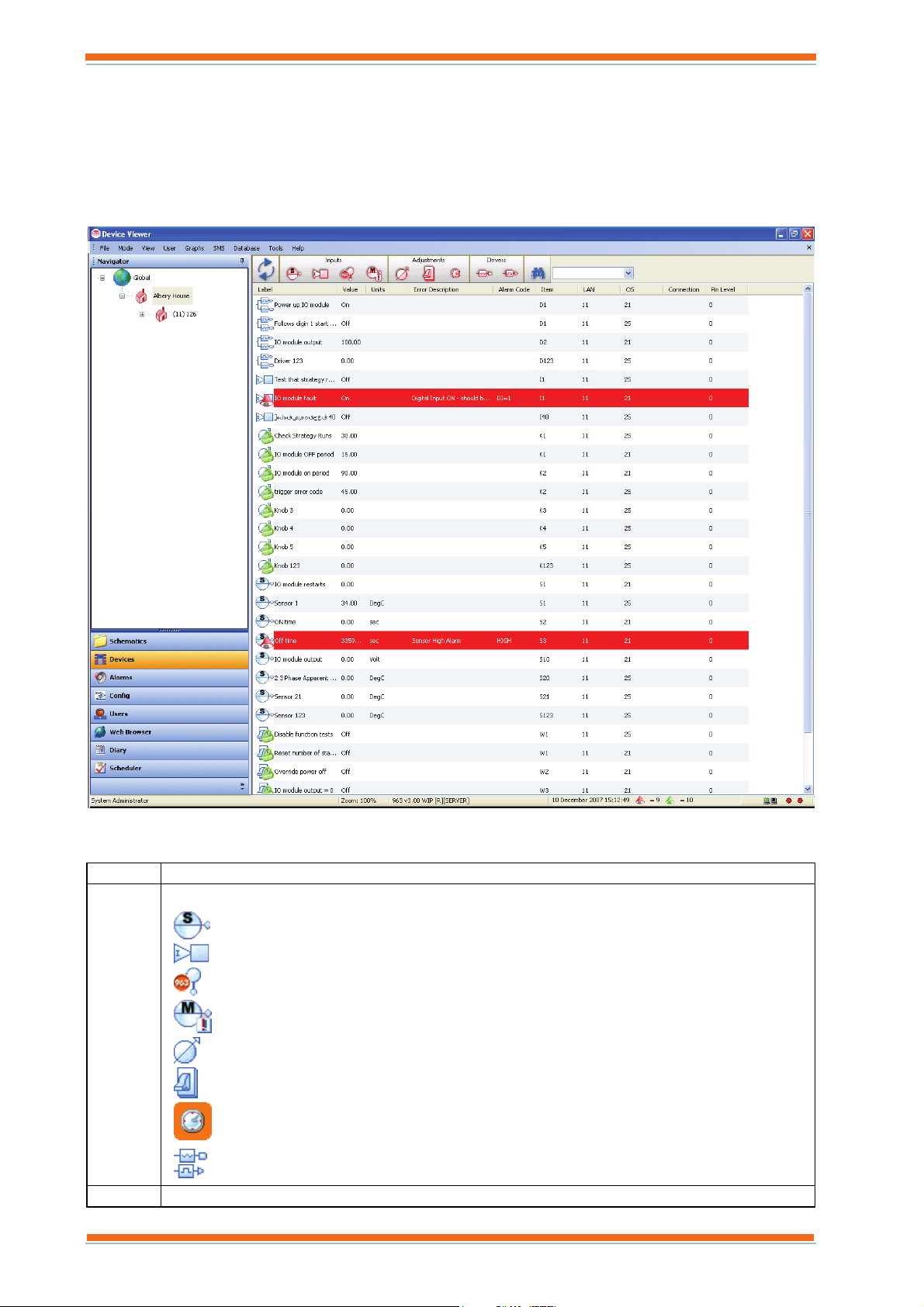
2.1.1.3 Device Viewer
The Device Viewer, shown below, enables inputs, outputs, adjustments, time zones, and critical alarms from the part of the system selected in the Navigator to be displayed, and for values to be adjusted, or graphed. E.g. if the internetwork is selected, all values from the internetwork are displayed. If a particular Lan is selected only values from that Lan are displayed. The display can be filtered further so that only modules whose label matches a search string are displayed. The display is colour coded to indicate whether the alarm is current. Red indicates that the alarm is current. Once the values have been displayed it is possible to adjust values, or display a graph.
It contains a number of columns that display the values of the inputs, outputs, adjustments, time zones, and critical
alarms.
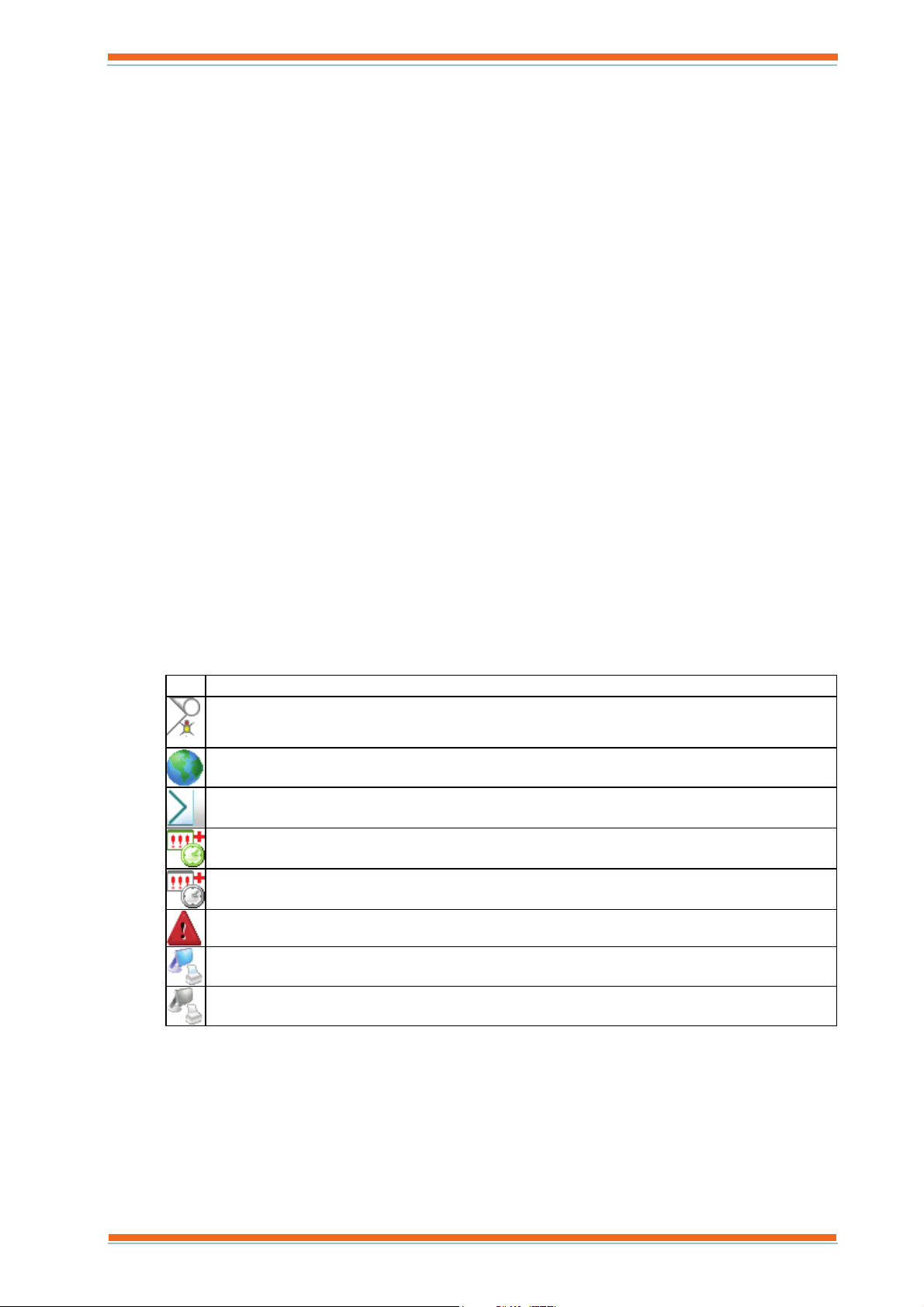
Column Description
Icon Contains an icon that indicates the module type.
Sensor Modules
Digital Input Modules
Virtual Sensor Modules
Critical Alarm Modules
Knob Modules
Switch Modules
Time zone Modules
Analogue Driver Modules
Digital Driver Modules
Label The module label.
963 User Guide TC200635 Issue 3 25/03/2008 12
Page 13
About 963
Column Description
Value The current value of the module.
Units The value’s engineering units.
Item A code indicating the module type and number (e.g. S1 specifies Sensor module number 1)
S Sensor Modules
I Digital Input Modules
W Switch Modules
Z Time zone Modules
K Knob Modules
D All Driver modules for IQ system sites, Analogue Driver Modules for BACnet sites
J Digital Driver Modules for BACnet sites
X Virtual Sensor Modules
M Critical Alarm Modules
LAN The Lan number of the controller containing the module
OS The network address of the controller containing the module
Tele The phone number or IP address used to address the site containing the module.
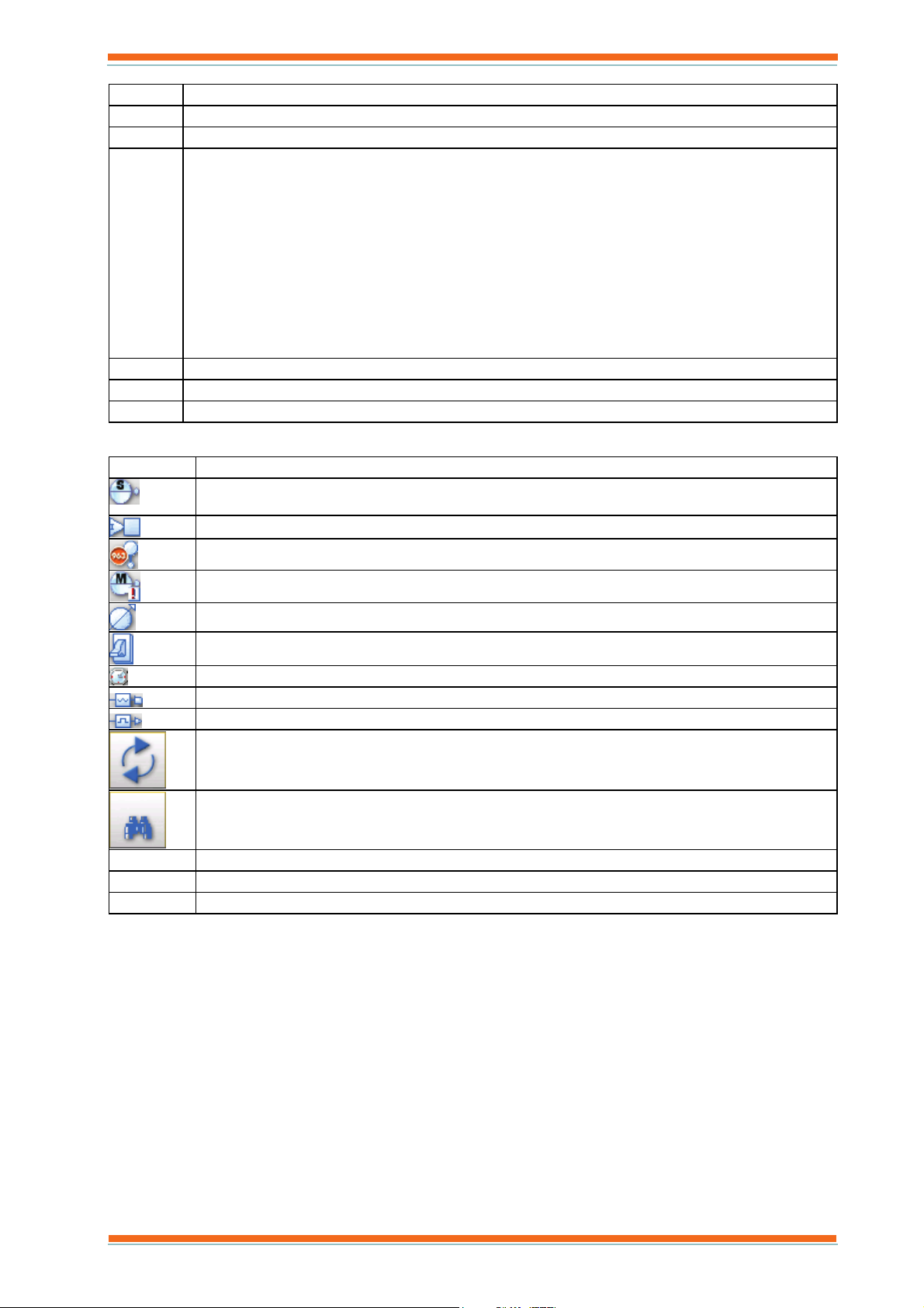
The display also contains a number of buttons that enable the types of modules displayed to be selected.
Icon What is Displayed
Sensors
Digital Inputs
Virtual sensors (calculated MKT values)
Critical Alarms
Knobs
Switches
Time Zones
Analogue Driver
Digital Driver
Refreshes the values.
This causes 963 to only display items of the selected item types whose label matches the search string.
Inputs
Adjustments
Drivers
Select/deselects all inputs
Select/deselects all adjustments
Select/deselects all drivers
Access to this display can be restricted.
963 User Guide TC200635 Issue 3 25/03/2008 13
Page 14
About 963
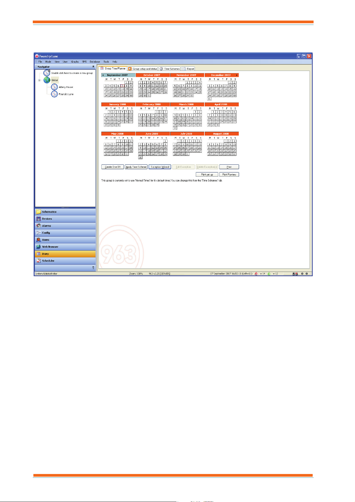
2.1.1.4 Diary Display
The Diary Display, shown below, provides information about there system's occupation times.
It has four tabs:
Group Time Planner
The Group Time Planner tab provides a calendar view of the occupation times for the diary group in diary
or groups selected in the Navigator. It indicates whether a day follows the normal occupation times for the
selected group, or an exception using colours. Information about exceptions can be displayed by clicking
the exception. A dot in the top right corner of a day indicates that the day has more than one exception
applied, moving the mouse over the day will display more information. Buttons enable exception sot be
added, edited, or deleted, and entire time schemes to be applied.
Group setup and status
The Group setup and status tab displays a list of the timezones that are linked to the diary group(s)
selected in the Navigator. The list indicates the site, Lan, controller name, timezone label, item code,
value, and device type. Buttons enable timezones to be added to the group, times to be sent to the
controllers, actual times to be viewed, and group setting to be edited.
Time Schemes
The Time Schemes tab displays the normal occupation times, and the time schemes that have been set up
for the Diary group selected in the Navigator in a list. Buttons enable new time schemes to be created,
existing one to be edited, or deleted, and time schemes to be imported from other diary groups.
Report
The Report tab provides information about the download of occupation times toe the diary group selected
in the Navigator. Buttons enable selection between a list of current download failure, all download
failures, and a full download history.
Access to this display can be restricted to certain users.
963 User Guide TC200635 Issue 3 25/03/2008 14
Page 15
About 963
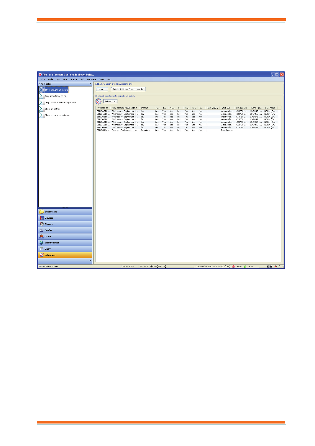
2.1.1.5 Event Scheduler Display
The Event Scheduler Display, shown below, displays a list of all the scheduled events that 963 is going to perform in the future. It displays events that 963 has been set to perform by the engineer; it also displays scheduled events created by 963’s Diary functions. The types of events can be filtered by clicking the required filter in the Navigator. It is used to organise and display all the automated actions carried out by 963, e.g. sensor-recording actions, or diary exceptions.
Access to this display can be restricted.
963 User Guide TC200635 Issue 3 25/03/2008 15
Page 16
About 963
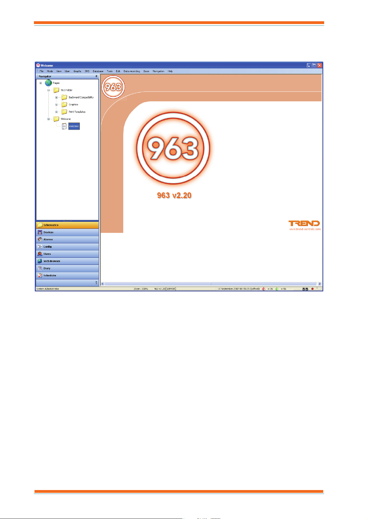
2.1.1.6 Schematic Page Display
The Schematic Page Display, shown below, enables a schematic page to be displayed. The Navigator displays a tree view of all the schematic pages, clicking a page will display it in the Data Display.
The Navigator provides a way of organising pages into folders, so that they can be located quickly, or to prevent
access to particular users.
963 User Guide TC200635 Issue 3 25/03/2008 16
Page 17
About 963
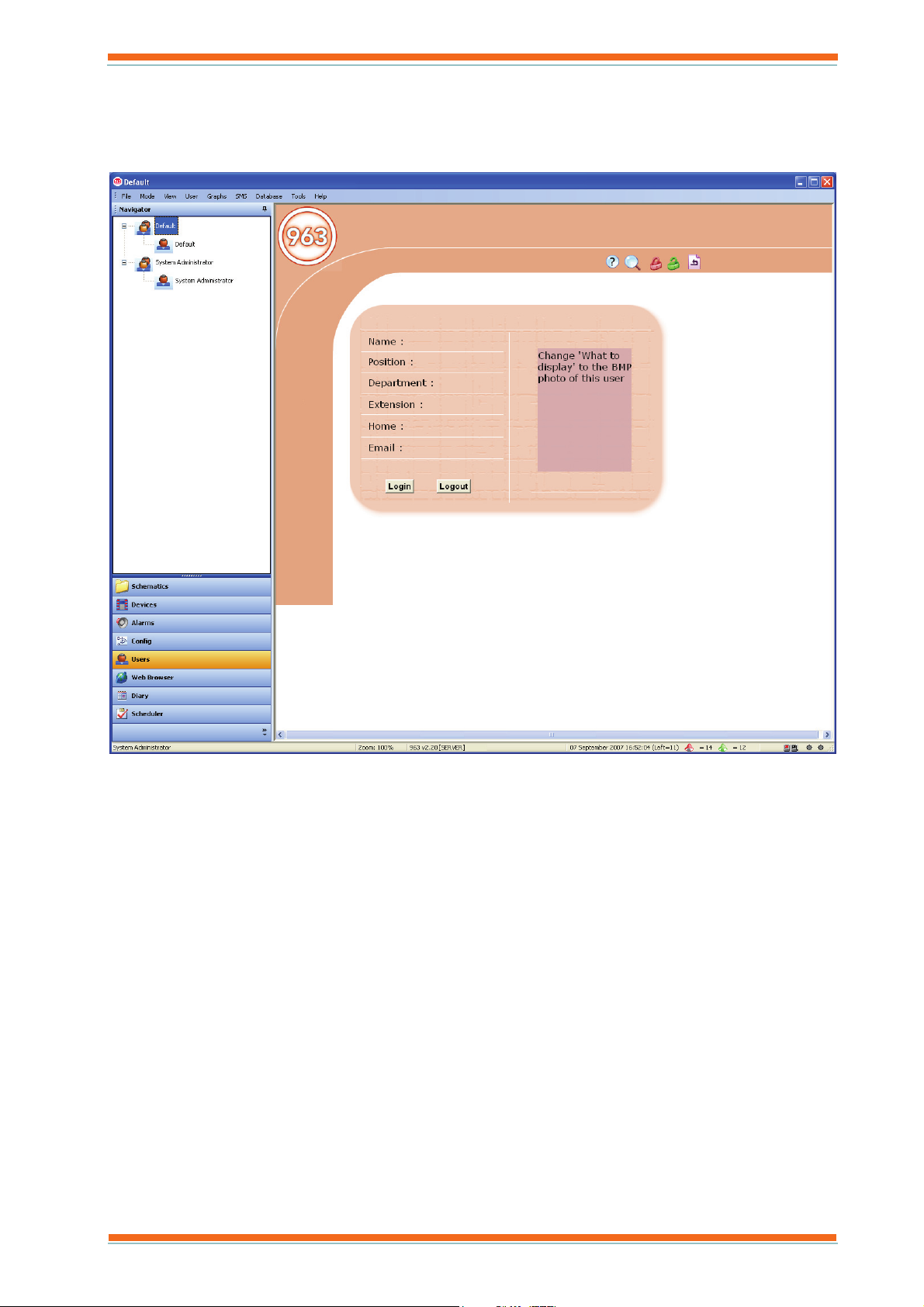
2.1.1.7 User Display
The User Display, shown below, Displays a page for the user selected in the Navigator. This page enables the user to log in, log off, or to change their password. It also enables the engineer to define access rights for people who require to use 963.
963 User Guide TC200635 Issue 3 25/03/2008 17
Page 18
About 963
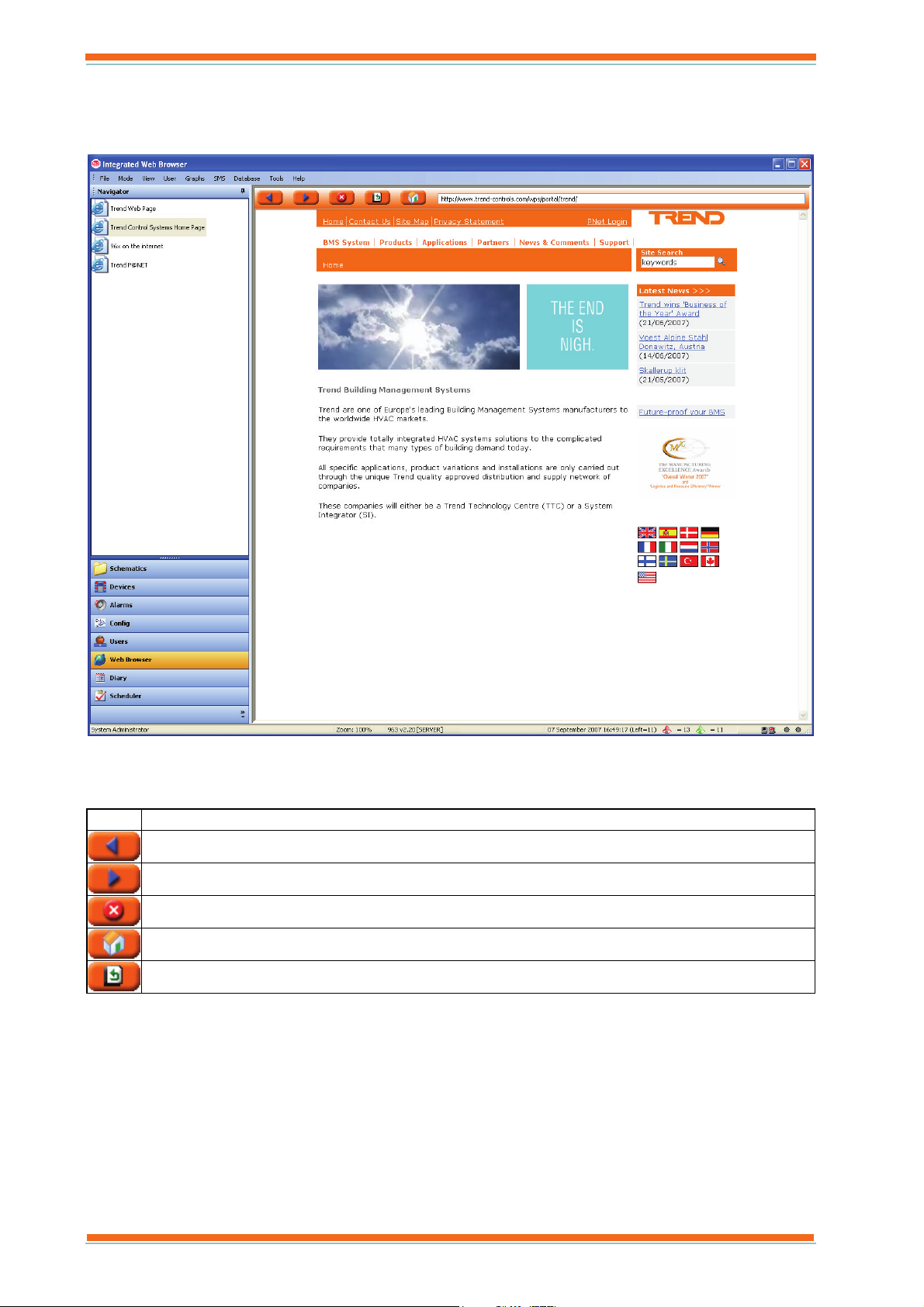
2.1.1.8 Web Browser Display
The Web Browser Display, shown below, enables selected web sites to be accessed. By default, it has some pages set up.
The Navigator displays the different sites that are available. Clicking a site in the Navigator will cause it to be
displayed in the Data Display. The top of the Data Display contains five buttons, shown below, that enable
navigation around the selected web site in a similar way to other web browsers.
Icon Description
Goes to the previous HTML page.
Goes to next HTML page.
Stops the current HTML page being uploaded.
Goes to the Home HTML page.
Updates the current HTML page.
Access to this display can be restricted.
963 User Guide TC200635 Issue 3 25/03/2008 18
Page 19
About 963
2.1.2 Menu Bar
The Menu Bar contains 963’s menus, which provide access to the application’s various features. The following menus are available:
Data Recording Menu
Database Menu
Edit Menu
File Menu
Help Menu
Graphs Menu
Mode Menu
Navigation Menu
SMS Menu
Tools Menu
User Menu
View Menu
Zoom Menu
The menus available at a particular time and the commands they contain will depend on the job currently being
carried out by 963.
If required the Menu Bar can be hidden, or made unavailable for some users.
2.1.3 Navigator
The Navigator appears on the left of the 963 Window. It allows the information displayed in the Data Display to be specified. For example, if a schematic page is displayed, the Navigator enables the page to be selected, whereas if the User Display is selected, it enables a particular user or workgroup to be selected. The contents of the Navigator associated with each display is described below:
Alarm Viewer
Displays a tree view the alarm handling structure containing Alarm filters, alarm groups, alarm priorities,
and retransmission destinations. It enables the alarms displayed in the Data Display to be selected. For
example, clicking an alarm filter will filter the alarms in the Data Display. Icons indicate the type of
object. The table below lists the different icons.
Icon Description
Alarm Filters Section
All Alarms
Alarm Filter
Alarm Group Section, and Default Alarm Group
Alarm Group
Alarm Priority, and Alarm Priority Level
Retransmission Destination Section (all retransmission destinations)
Retransmission Destination
963 User Guide TC200635 Issue 3 25/03/2008 19
Page 20
About 963
Configuration Mode Display
Displays a tree view of the system to which 963 is connected enabling the controller for which
configuration mode is required to be selected. Clicking a controller will cause it to enter configuration
mode, and the configuration prompts displayed in the Data Display. Icons indicate the type of object. The
table below lists the different icons.
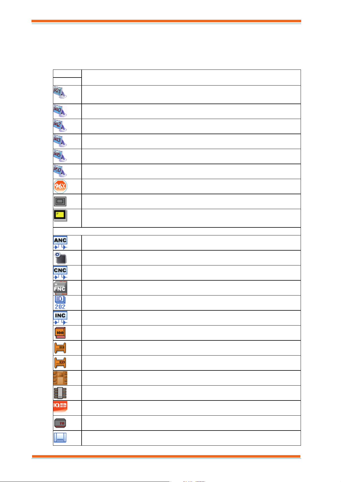
Icon
Supervisors
Devices
Description
921 Supervisor
940 Supervisor
942 Supervisor
943 Supervisor
945 Supervisor
950 Supervisor
963 Supervisor, 962 Supervisor, S2 Supervisor, or ViewPoint
NDP
IQView
ANC
BACnet Device
CNC
FNC
ID200
INC
IQ100 Controller
IQ111 Controller
IQ131 Controller
IQ151 Controller
IQ2 Controller
IQ3 Controller
IQ70 Controller
IQ90 Controller
963 User Guide TC200635 Issue 3 25/03/2008 20
Page 21
About 963
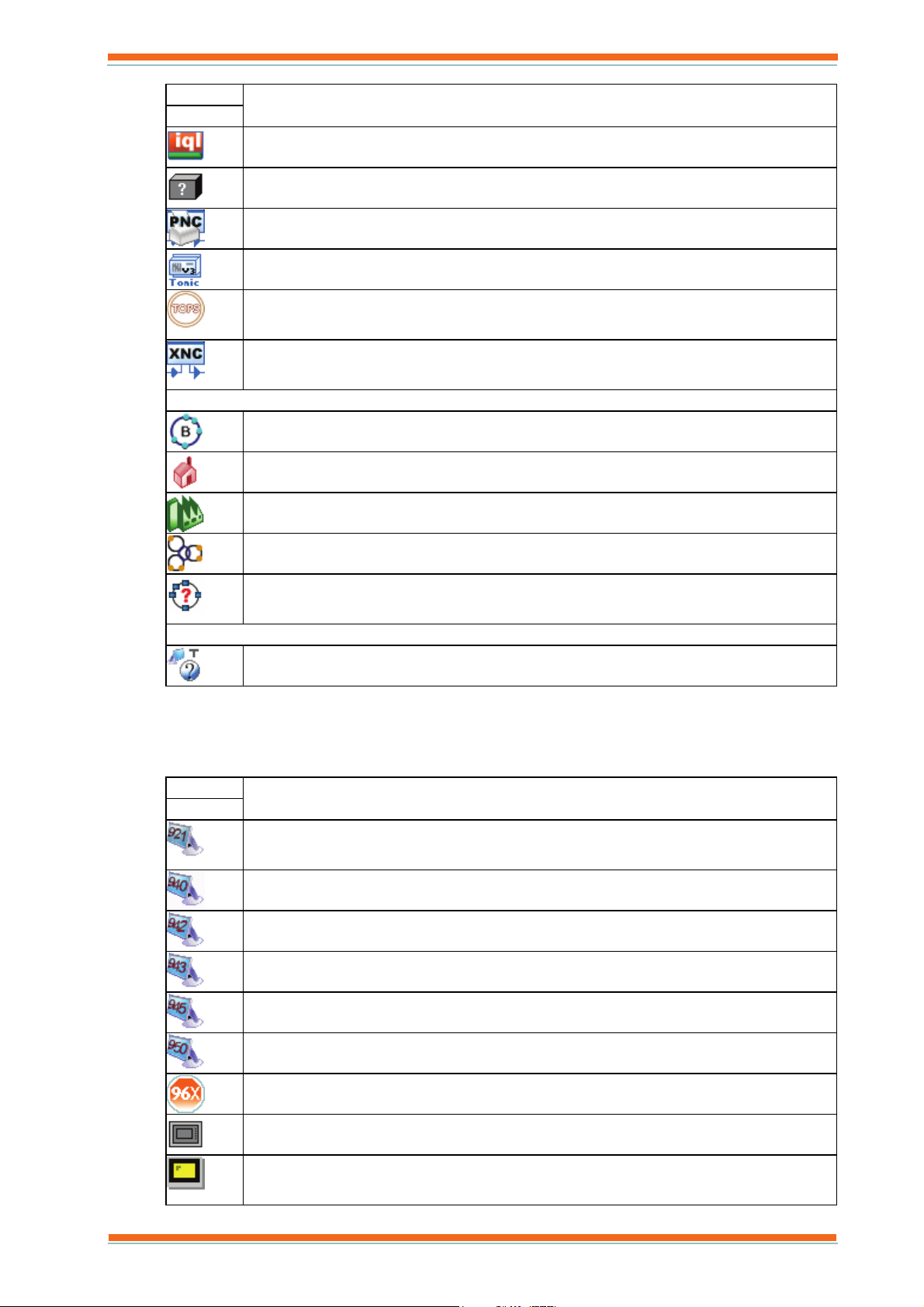
Icon
Description
Supervisors
IQL Controller
Non IQ system device
PNC
TONIC
TOPS
XNC
Site Structure
BACnet Lan
Local site
Remote Site
Trend Lan
Unknown Lan
General
Unknown Device
Device Viewer
Displays a tree view of the system to which 963 is connected, enabling the level at which the system is
displayed in the Data Display to be selected. For example, clicking a Lan will display all the points with
labels on that Lan. Icons indicate the type of object. The table below lists the different icons.
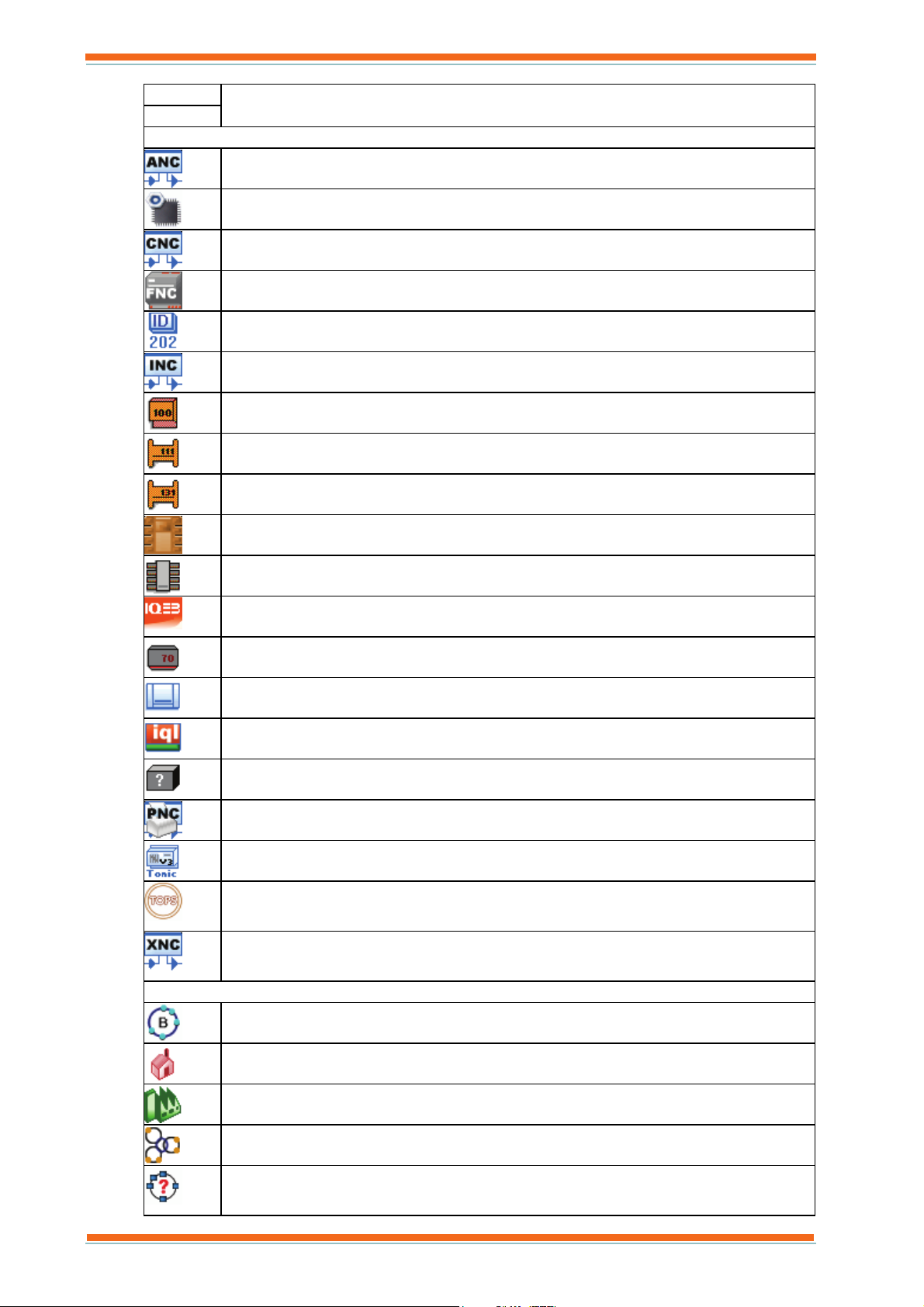
Icon
Description
Supervisors
921 Supervisor
940 Supervisor
942 Supervisor
943 Supervisor
945 Supervisor
950 Supervisor
963 Supervisor, 962 Supervisor, S2 Supervisor, or ViewPoint
NDP
IQView
963 User Guide TC200635 Issue 3 25/03/2008 21
Page 22
About 963
Icon
Supervisors
Devices
Description
ANC
BACnet Device
CNC
FNC
ID200
INC
IQ100 Controller
IQ111 Controller
IQ131 Controller
IQ151 Controller
IQ2 Controller
IQ3 Controller
IQ70 Controller
IQ90 Controller
IQL Controller
Non IQ system device
PNC
TONIC
TOPS
XNC
Site Structure
BACnet Lan
Local site
Remote Site
Trend Lan
Unknown Lan
963 User Guide TC200635 Issue 3 25/03/2008 22
Page 23
About 963
Icon
Description
Supervisors
General
Unknown Device
Diary Display
Displays a tree view of all the diary groups and folders. Clicking a group will display the associated times
in the Data Display. Icons indicate the type of object. The table below lists the different icons.
Icon Description
Diary Groups Section (all diary groups)
Diary Group
New Diary Group
Event Scheduler Display
Displays a list of different types of events. Clicking one of these will display a list of events of that type in
the Data Display.
Schematic Page Display
Displays the available schematic pages. It allows the pages to be organised into folders to make locating the
required page easier. Clicking a folder will expand it to display any sub folders, or pages. Click a page will
cause it to be displayed in the Data Display. Folders can be set up with user access levels to prevent
particular users accessing them. Pages not in a folder are always visible to all users. Each folder can contain
both folders and pages. Icons indicate the type of object. The table below lists the different icons.
Icon Description
All Schematic Page
Folder of schematic pages
Schematic Page
User Display
Displays a tree view of all the workgroups and users. Clicking a workgroup will expand it revealing the
users in that workgroup. Clicking a particular user will display that user’s login page in the Data Display.
Icons indicate the type of object. The table below lists the different icons.
Icon Description
Workgroup
User
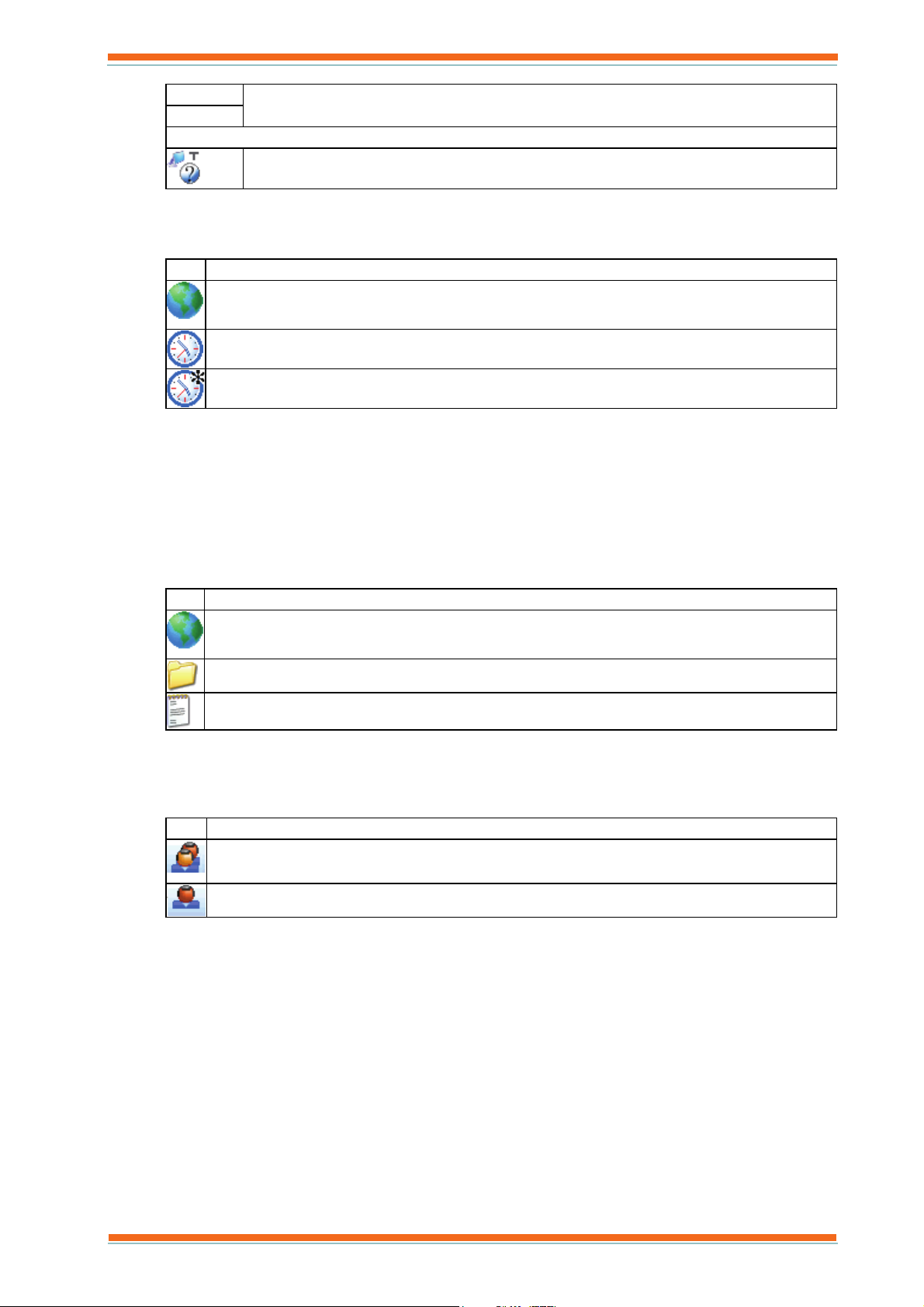
Web Browser Display
Displays a list of web sites that can be selected. Clicking one will cause it to be displayed in the Data
Display.
963 User Guide TC200635 Issue 3 25/03/2008 23
Page 24
About 963
2.1.4 Network Comms Status Lights
The Network Comms Status Lights appear at the bottom of the 963 Window. They provide information about the
status of communications in and out of the node connecting 963 to the IQ network, and the status of any remote
connection devices on the system.
TX and RX indicators: These flash green when 963 is receiving, or transmitting information. If they appear
grey, 963 has been unable to locate the CNC.
Remote connection indicator: If grey, all of the devices are available for use, if red, at least one of them is
attempting to make a connection, and if green, at least one is connected. Clicking this icon displays the Remote
Connection Window.
If 963 has been licenced with SMS Direct an additional icon (
) is displayed. This icon indicates the status of the
modem, if a 963 is busy talking to the phone the icon will flash between green and red. The icon will be grey if the
is a problem communicating with the phone. If the PIN for the modem is incorrect, an exclamation mark will appear
next to the icon. Clicking this icon displays the SMS Activity Window.
2.1.5 Selection Buttons
The Selection Buttons, shown below, appear at the bottom of the Navigator of the 963 Window. They provide access to the 963’s different displays. Access to these buttons can be protected, preventing unauthorised users accessing the displays.
Button Information Displayed
Alarm Viewer.
Configuration Mode Display.
Device Viewer.
Web Browser Display.
Event Scheduler Display.
Diary Display.
Schematic Page Display.
User Display
If a button is greyed out, this indicates that the user currently logged on does not have access to that display. It is
also possible to minimise buttons that are not used very often doing this displays the button as shown below.
Clicking these minimised buttons will also display the corresponding display. Buttons can also be hidden from the
toolbar as required.
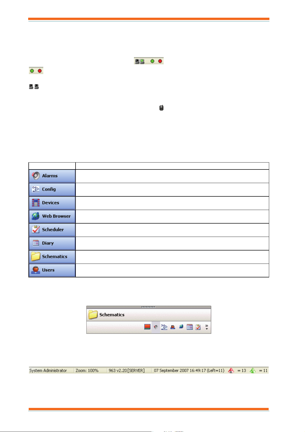
2.1.6 Status Bar
The Status Bar, shown below, is located at the bottom of the 963 Window. It provides information about the
version of 963, the name of the user that is currently logged on, and the number of alarms that are left to
acknowledge, as well as the current date and time.
The name of the user currently logged on is displayed in the left of Status Bar, the version of 963 in the next column, with the number of occurred alarms waiting to be actioned (red bell), number of cleared alarms waiting to be actioned (green bell) and the current date and item in the last one.
963 User Guide TC200635 Issue 3 25/03/2008 24
Page 25
About 963
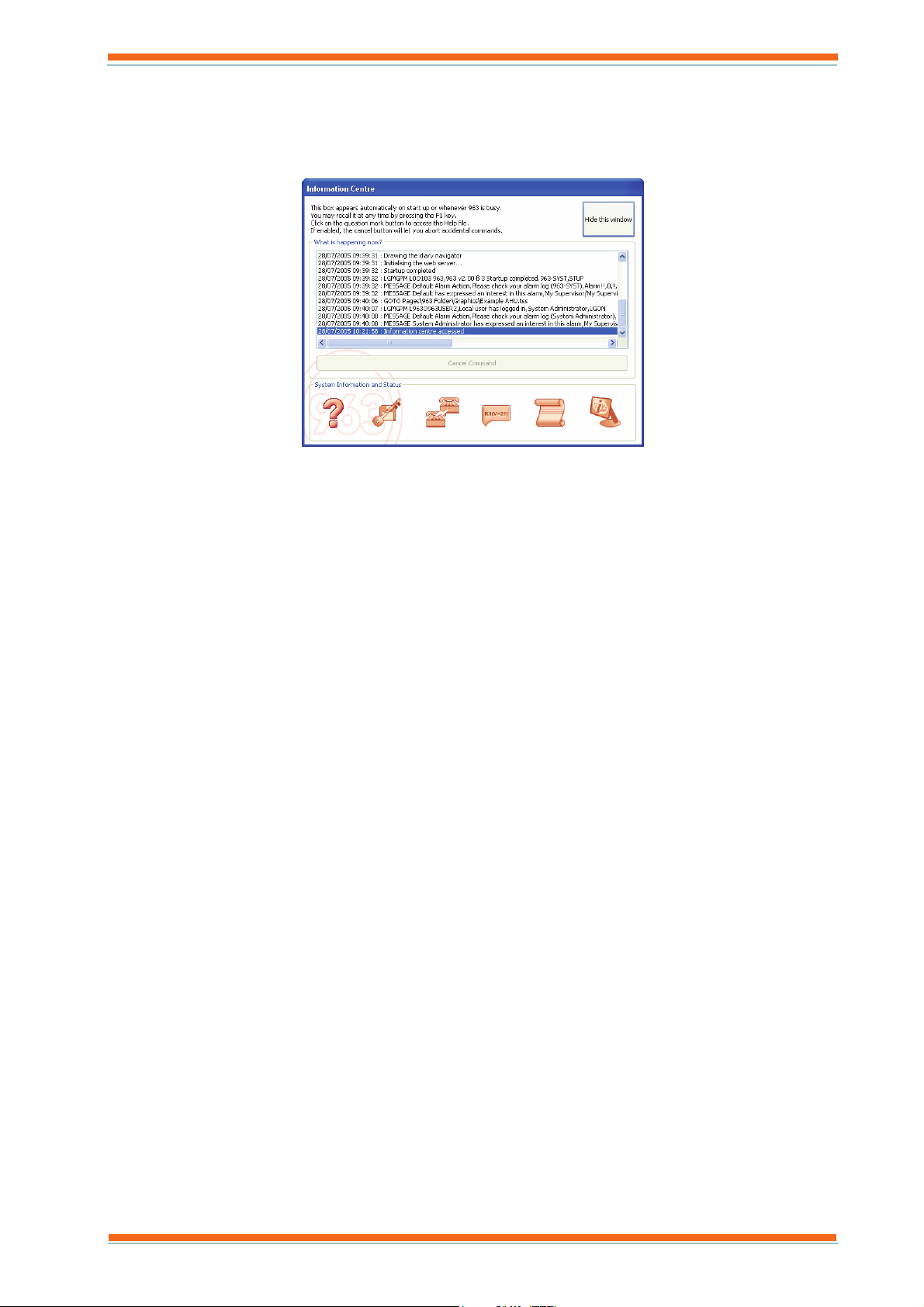
2.2 The Information Centre Window
The Information Centre Window, shown below, is designed to inform the user what 963 is doing (i.e. starting up,
downloading times etc), and to provide access to more detailed information such as communications. It is
automatically displayed when 963 is performing a task, but can also be displayed when required by pressing F1.
The information about what 963 is currently doing is displayed in the What is happening now? box. The current
command can be cancelled by clicking Cancel Command.
The buttons at the bottom of the window provide access to licence details, communications information, autodialler
status, system information, script information, and the on-line help.
Note that the availability of these buttons is dependent on the user’s level of authority, therefore some of the buttons
may be greyed out.
963 User Guide TC200635 Issue 3 25/03/2008 25
Page 26

About 963
This page is intentionally left blank.
963 User Guide TC200635 Issue 3 25/03/2008 26
Page 27
Using 963
3 USING 963
This section describes how to use 963. It describes all the necessary tasks required to operate 963, and make
adjustments to the system once it has been correctly engineered. A summary of using 963 is provided in the 'Basic
Use' section of this manual. For a more detailed description of the different tasks see the following sections:
Action Alarms Adjust Occupation Times
Adjust Values Administer the System
Control Scripts Display a Schematic Page
Display Graphs Display IQ3 Web Pages
Display Scheduled Events Display the Information Centre
Display the IQ System Display HTML Pages
Enter Configuration Mode on Pre IQ3 Controllers Insert a List into an HTML File
Layout the Window Manage Your User Account
Playback Recorded Data Record Data
Save a List to HTML Send an SMS Message
Setup Exception Templates View Alarms
View Communications Information View Occupation Times
3.1 Basic Use
This section of the manual describes the most basic use of the 963. It assumes that the user only has access to the
pages that have been engineered. Most of the information presented to the user is displayed on schematic pages that
have been set up. Clicking certain parts of the page will cause something to happen; exactly what happens is
dependent on how the 963 is set up. When the mouse pointer is moved over a part of the screen that will do
something it changes to a hand (
in, or next to them.
). These areas of the screen will generally be obvious because of text that appears
To use 963:
1. On the Start menu point to All Programs point to Trend Control Systems and click 963 to run 963.
2. On the User menu click Log in and enter your user name and password to log in as described in the ‘Log
In’ section of this manual. It is necessary to log in so that 963 knows what information and facilities you
are able to access.
Remember the username is case sensitive.
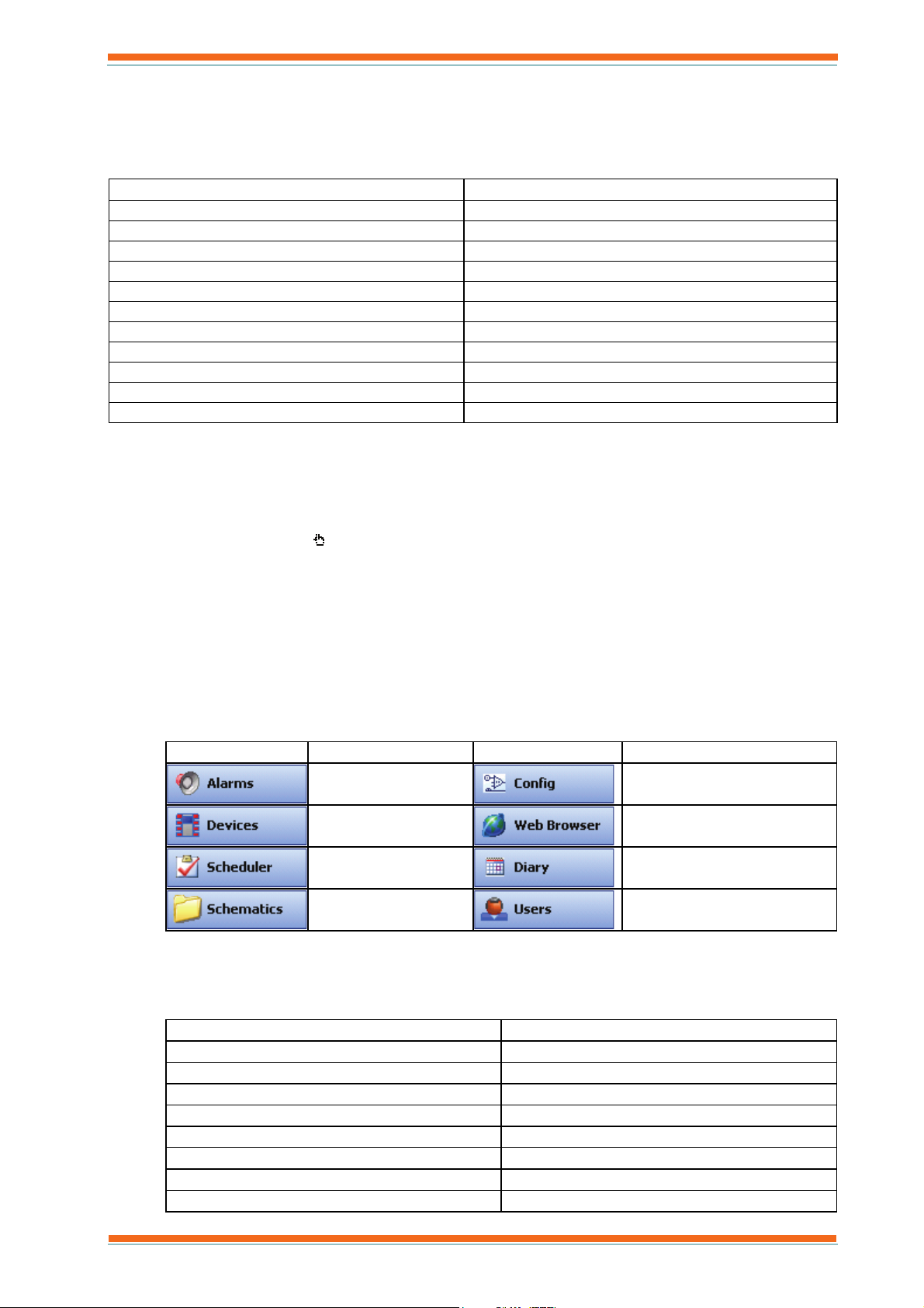
3. In the Navigator click the appropriate Selection Button to select the required display. These are listed in
the table below. For details about each of the displays see the ‘The 963 Window’ section of this manual.
Button Description Button Description
Displays the Alarm
Viewer.
Displays the Device
Viewer.
Displays the Event
Scheduler Display.
Displays the Schematic
Page Display.
4. Once you have selected the required display you will be able to view the information such as schematic
pages, the Device Viewer, and alarms. Clicking the different objects will enable you to perform different
tasks the display should make it clear what can be done. The table below lists the common tasks you should
see the corresponding section of this manual for more details.
Action Alarms Adjust Occupation Times
Adjust Values Administer the System
Control Scripts Display a Schematic Page
Display Graphs Display IQ3 Web Pages
Display Scheduled Events Display the Information Centre
Display the IQ System Display HTML Pages
Enter Configuration Mode on Pre IQ3 Controllers Insert a List into an HTML File
Layout the Window Manage Your User Account
Playback Recorded Data Record Data
Displays the Configuration
Mode Display.
Displays the Web Browser
Display.
Displays the Diary Display.
Displays the User Display.
963 User Guide TC200635 Issue 3 25/03/2008 27
Page 28
Using 963
Save a List to HTML Send an SMS Message
Setup Exception Templates View Alarms
View Communications Information View Occupation Times
5. Log off as described in the ‘Log Off’ section of this manual when the use of 963 is finished.
3.1.1 Run 963
963 can run in the same way as any Windows application, from the Start menu, from a shortcut, or from the
Taskbar. 963’s installation process adds an option to run it from the Start menu.
To run 963:
1. On the Start menu point to All Programs and then point to Trend Control Systems and click 963.
If 963 has been licenced, it will run up displaying the 963 Window. An icon
is displayed at the bottom left of the
screen. If 963 is not licenced a message indicating how many days you have left to evaluate the product will be
displayed.
Note that 963 is to access information on a BACnet network (963 BACnet), and TOPS has been installed on a
different PC to 963 TOPS must be running. See the 'Start TOPS Manually' section of the 963 Engineering Manual
(TE200637).
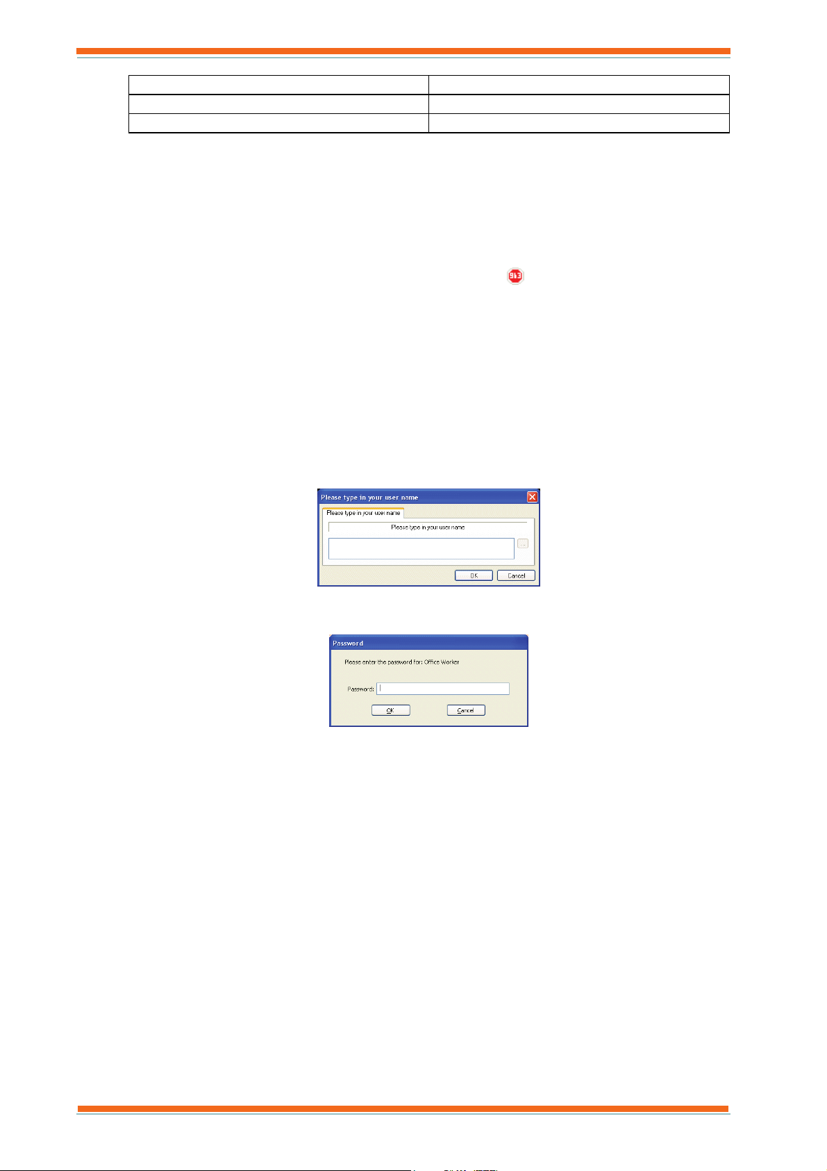
3.1.2 Log In
Before 963 can be used, it is necessary to log in so that 963 knows what information and facilities you are able to
access.
To log in:
1. On the User menu click Log in. The Please type in you username dialogue box displayed.
2. In the box enter your username. Remember the username is case sensitive.
3. Click OK. The Password dialogue box is displayed.
4. In the Password box enter your password.
Note that passwords are case sensitive.
5. Click OK.
Note that a button may have been provided on the page that enables you to log in.
3.1.3 Log Off
Once use of 963 is finished, it is advisable to log off to prevent unauthorised changes being made.
To log off:
1. On the User menu click Log off.
Note that if left unattended for a period of time 963 may automatically log the current user off if it has been
configured in this way.
It is recommended that after logging off, the computer be locked to prevent other people accessing the PC.
Note that a button may have been provided on the page that enables you to log off.
963 User Guide TC200635 Issue 3 25/03/2008 28
Page 29
Using 963
3.1.4 Close 963
963 should be left running all the time to ensure alarms are processed correctly, and other tasks carried out.
However it can be closed.
To close 963:
1. Log in as described in the ‘Log In’ section of this manual.
2. On the File menu click Exit, or click
displayed.
3. Click Yes.
Note that not all users will be able to close 963.
. A dialogue box asking if you are sure you want to close 963 is
3.2 Display a Schematic Page
This section of the manual describes how to access and use the 963’s schematic pages. Most of the information
presented to the user is displayed on schematic pages that have been set up. Clicking certain parts of the page will
cause something to happen; exactly what happens is dependent on how the 963 is set up. When the mouse pointer is
moved over a part of the screen that will do something it changes to a hand (
generally be obvious because of text that appears in, or next to them.
To display a schematic page:
1. Run 963 as described in the ‘Run 963’ section of this manual.
2. On the User menu click Log in to log in and enter your user name and password as described in the ‘Log
In’ section of this manual. A schematic page may now be displayed if not got to (3) if one is displayed go
to (4).
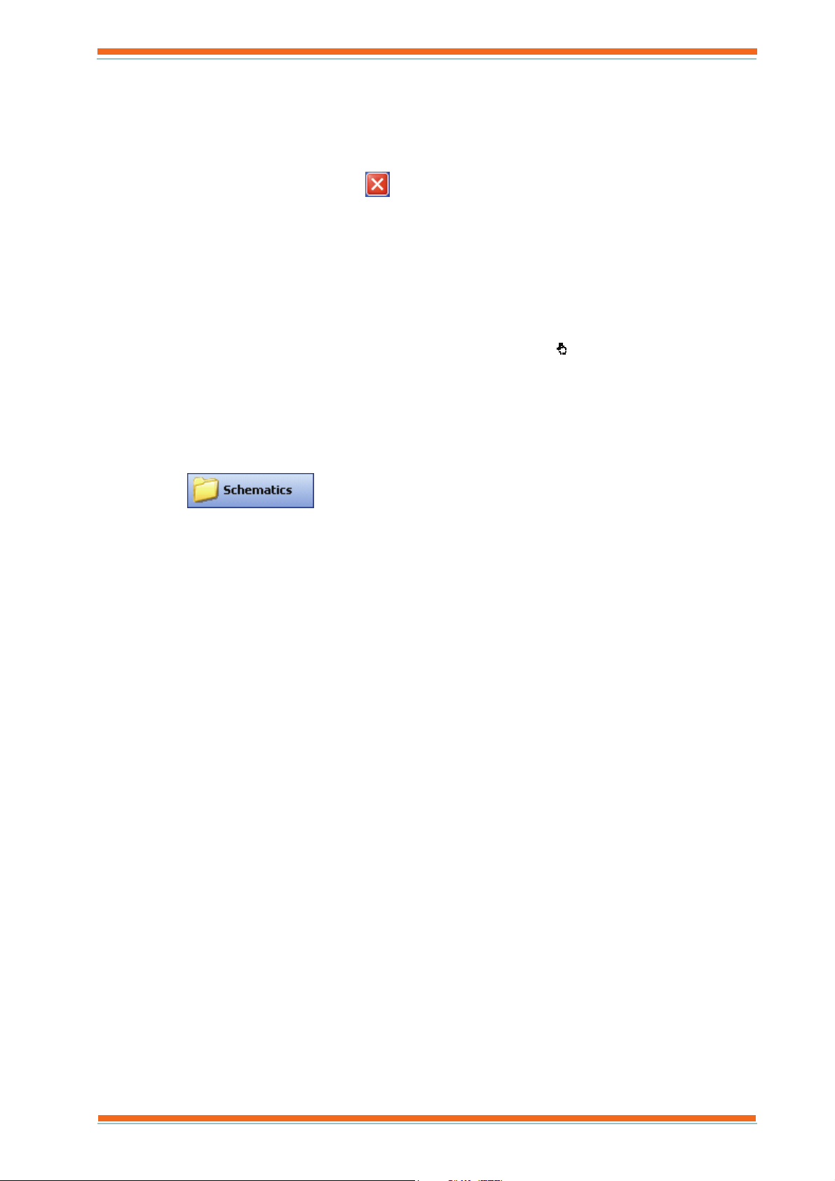
3. Click
Display.
4. Click the button or picture that displays the required page or click on the page in the Navigator. To display
the page in a new window hold down the CTRL key and click the button or picture. To move from page to
page click the button or picture that provides access to the required page.
As you move from page to page 963 keeps a record of the pages and enables you to move backwards and
forwards through the pages. To do this on the Navigation menu click Move backwards or Move
forwards, or right-click the page and click Forward or Backward.
or on the Mode menu click Schematics to select the Schematic Page
). These areas of the screen will
Note that the Navigator can be refreshed by right clicking it, and clicking Refresh View from the displayed
menu.
5. Once the required page is displayed you will be able to view the information, clicking the different objects
will enable you to perform different tasks the page display should make is clear what can be done.
Values can be adjusted by clicking the button or picture that enables the value to be changed and specifying
the new value. Values that have been overridden ON/OFF will have a flashing border unless configured
otherwise. Compact graphs can be displayed by clicking the value that is to be graphed. Precision graphs
can be displayed by right-clicking the value and clicking Collect full precision log graph(s). The page can
be made to fit completely in the display area by right-clicking the page and on the displayed menu clicking
Fit to page, or on the Zoom menu click Fit to page. If it has been set up a list of points associated with a
value can be displayed by holding down the CTRL key and clicking the value. Configuration parameters of
the configuration modules within IQ controllers can be viewed by right clicking on a value and clicking
Edit Item from the displayed menu. Clicking Home from the User menu will display the schematic page
displayed when you first logged in.
6. Log off when the use of 963 is finished.
963 User Guide TC200635 Issue 3 25/03/2008 29
Page 30

Using 963
3.2.1 Zoom in and Out of a Schematic Page
It is possible to zoom in and out on any schematic page so that the data can be more easily seen.
To zoom in:
1. On the Zoom menu click Zoom in, or right-click anywhere on the page and on the displayed menu point to
Zoom and click Zoom in. The pointer will change to a
.
2. Hold down the left mouse button, and drag the mouse over the required area, or click the mouse button to
zoom in one level.
3. Release the mouse button.
To zoom out:
1. On the Zoom menu click Zoom out, or right-click anywhere on the page and on the displayed menu point
to Zoom and click Zoom out. The pointer will change to a
.
2. Click the mouse button to zoom out one level.
3. Release the mouse button.
To zoom out again, repeat the process.
To return to the original zoom level:
1. On the Zoom menu click Zoom to original, or right-click anywhere on the page and on the displayed
menu point to Zoom and click Zoom to original.
To zoom with a mouse wheel:
1. Hold down the CTRL key and use the mouse wheel to zoom in and out.
3.2.2 Print a Schematic Page
963 can print out schematic pages to any Windows printer accessible to the PC running 963.
To print a page:
1. View the page as described in the ‘Display a Schematic Page’ section of this manual.
2. On the File menu point to Print and click Print, or right-click anywhere on the page and on the displayed
menu point to Print and click Print. The Print dialogue box is displayed.
3. In the Name box click the required printer.
Note that changing the printer from here will change the page printer used by 963 to print out pages,
graphs, and alarm priority statistics.
4. If necessary click Properties to set up the printer as required.
5. In the Number of copies box enter the number of copies required.
6. If a print template is to be used select the Use Template check box, and click the required template from
the list.
Note that if the print template changed the 963 will remember it, and that will be the template selected next
time.
7. Click OK.
You can preview what will be printed by pointing to Print on the File menu and clicking Print Preview, or rightclicking the page, and on the displayed menu pointing to Print and clicking Print Preview.
963 User Guide TC200635 Issue 3 25/03/2008 30
Page 31

Using 963
3.3 Adjust Values
3.3.1 Adjust Knob Values
3.3.1.1 Adjust a Knob in a Trend Device
The value of knobs in Trend devices can be adjusted from a schematic page or from the Device Viewer.
To adjust a knob in a Trend device:
1. Display the page containing the knob that is to be adjusted and click the button that enables it to be
changed.
Or
View the knob that is to be adjusted in the Device Viewer, right-click the knob, and click Adjust Point.
2. At this point you may be asked if you are sure you want to make the adjustment click Yes.
A dialogue box is displayed.
3. Enter the new value by typing it in, clicking the numbers, or clicking << or >> to decrement/increment the
value.
4. Click Enter.
3.3.1.2 Adjust a Knob (Analogue Value) in a BACnet Device
Analogue values in a BACnet devices are represented in 963 as knobs, these can be adjusted from a schematic page
or from the Device Viewer.
To adjust knob (analogue value) in a BACnet device:
1. Display the page containing the knob representing the analogue value that is to be adjusted and click the
button that enables the value to be changed.
Or
View the knob representing the analogue value that is to be adjusted in the Device Viewer, right-click the
knob, and click Adjust Point.
2. At this point you may be asked if you are sure you want to make the adjustment click Yes.
A dialogue box is displayed.
3. Enter the new value by typing it in, clicking the numbers, or clicking << or >> to decrement/increment the
value.
4. Click Enter.
Important: When 963 adjusts a value in a BACnet device it writes the value into the value's priority array.
The value will remain in the array, and be used when it is the highest. Therefore making the adjustment does
not mean that it will be the value that is used. If required the 963's adjustment can be removed from the
array by relinquishing control.
963 User Guide TC200635 Issue 3 25/03/2008 31
Page 32

Using 963
3.3.2 Adjust Switches
3.3.2.1 Adjust a Switch in a Trend Device
Switches in a Trend device e.g. controller can be adjusted from a schematic page or from the Device Viewer.
To adjust a switch in a Trend device:
1. Display the page containing the switch that is to be adjusted and click the button that enables it to be
changed.
Or
View the switch that is to be adjusted in the Device Viewer, right-click the switch, and click Adjust Point.
The Adjust Point dialogue box is displayed.
Note that the display of the dialogue box can be disabled meaning that the adjustment occurs immediately.
2. Click Yes.
3.3.2.2 Adjust a Switch (Digital Value) in a BACnet Device
Digital values in BACnet devices are represented in 963 as switches, these can be adjusted from a schematic page or
from the Device Viewer.
To adjust a switch (digital value) in a BACnet device:
1. Display the page containing the switch representing the digital value that is to be adjusted, and click the
button that enables it to be changed.
Or
View the switch representing the digital value that is to be adjusted, in the Device Viewer, right-click the
switch, and click Adjust Point.
The Switch Adjuster dialogue box is displayed.
2. Select the Adjust switch status option.
3. Click OK. The Adjust Point dialogue box is displayed.
Note that the display of the dialogue box can be disabled meaning that the adjustment occurs immediately.
4. Click Yes.
Important: When 963 adjusts a value in a BACnet device it writes the value into the value's priority array.
The value will remain in the array, and be used when it is the highest. Therefore making the adjustment does
not mean that it will be the value that is used. If required the 963's adjustment can be removed from the
array by relinquishing control.
963 User Guide TC200635 Issue 3 25/03/2008 32
Page 33

Using 963
3.3.3 Adjust a Module Parameter
It is possible to adjust certain parameters of the configuration modules within IQ controllers directly from a
schematic page or the Device Viewer.
To adjust a module parameter:
1. Display the page containing value from the controllers whose configuration parameters are to be adjusted.
Or
View the value from the controllers whose configuration parameters are to be adjusted in the Device
Viewer, right-click the value, and click Adjust Point.
2. Right-click the value, and click Edit Item. The View as Points dialogue box is displayed.
3. Right-click the parameter that is to be changed, and click Adjust Point from the menu that is displayed.
The Enter new value for dialogue box is displayed.
4. In the box enter the new value.
5. Click OK, to return to the View as Points dialogue box and then
to close the View as Points dialogue
box.
963 User Guide TC200635 Issue 3 25/03/2008 33
Page 34

Using 963
3.3.4 Relinquish Control of a BACnet Value
When 963 adjusts a value in a BACnet device it writes the value into the value's priority array. The value will
remain in the array, and be used when it is the highest. If required the 963's adjustment can be removed from the
array by relinquishing control.
Relinquish control of an analogue value:
1. Display the page containing the value for which you want to relinquish control, and click the button or
picture that enables the value to be changed.
Or
View the value for which you want to relinquish control in the Device Viewer, right-click the value, and
click Adjust Point.
2. At this point you may be asked if you are sure you want to make the adjustment click Yes.
A dialogue box is displayed.
3. Select the Relinquish control check box.
4. Click Enter.
Relinquish control of a digital value:
1. Display the page containing the value or which you want to relinquish control, and click the button or
picture that enables the value to be changed.
Or
View the value for which you want to relinquish control in the Device Viewer, right-click the value, and
click Adjust Point.
The Switch Adjuster dialogue box is displayed.
2. Select the Relinquish control option.
3. Click OK. The Adjust Point dialogue box is displayed.
963 User Guide TC200635 Issue 3 25/03/2008 34
Page 35

Using 963
3.4 Alarms
3.4.1 View Alarms
963 indicates that an alarm has been received from the IQ system by carrying out any actions that have been
engineered.
Alarms are shown as they arrive on the Incoming Alarms tab of the Alarm Viewer. This list stores the last 100
alarms. After alarms have been processed, they will appear in the Alarm History tab. In both of the lists icons
indicate whether or not an alarm has been actioned by a user. Colours are used to indicate whether the alarm is a set
alarm or a cleared alarm. A red bell indicates a set alarm, and a green bell indicates a cleared alarm. If the alarm has
been actioned by the user the bell with appear with a tick over it. The table below shows the different icons.
Icon Description
Set alarm that has not been actioned.
Set alarm that has been actioned.
Cleared alarm that has not been actioned.
Cleared alarm that has been actioned.
The Alarm History tab is colour coded to indicate whether or not the alarm is current. Red indicates that the alarm
is current.
There are a number of different ways in which alarms can be viewed:
View Alarms for a Particular Point
View Incoming Alarms
View Alarm History
View Alarms for an Alarm Panel
View Alarm Priority Statistics
View an Audit Trail
View the Current Value
3.4.1.1 View Alarms for a Particular Point
It is possible to view all the alarms for a particular point that is displayed on a schematic page, or from any point
displayed in the Device Viewer.
To view alarms for a particular point:
1. Display the page containing the point, or display the required point in the Device Viewer.
2. Right-click the point for which alarms are to be viewed, and on the displayed menu List of alarms. The
List of alarms dialogue box is displayed listing all the alarms that have occurred for that point. If there are
more than 500 alarms for the point <500 and 500> buttons will be enabled to provide access to the others.
3. To close the window click OK.
The alarms can be actioned by clicking the alarm to select it, and then clicking Action. All alarms can be
actioned by clicking Action all un-actioned alarms in the list. The list in the dialogue box can be printed
by right-clicking anywhere in the list, and on the displayed menu clicking Print this page. It can also be
saved to an HTML file, or inserted in an existing HTML file in a similar way.
963 User Guide TC200635 Issue 3 25/03/2008 35
Page 36

Using 963
A
3.4.1.2 View Incoming Alarms
Alarms are shown as they arrive on the Incoming Alarms tab of the Alarm Viewer. This list stores the last 100
alarms.
To view incoming alarms:
1. Log in as described in the ‘Log In’ section of this manual.
2. Click
or on the Mode menu click Alarms to select the Alarm Viewer.
3. Click the Incoming Alarms tab.
More information about a particular alarm can be displayed by clicking the alarm. This will display a
balloon containing information about the alarm, moving the mouse will cause the balloon to disappear. If
the text does not fit in the column, the column can be resized by dragging the edge to the correct size.
Clicking Clear List will clear the list.
Note that the Device Viewer provides an indication of any supported value on the system in an alarm condition. See
the ‘Display the IQ System’ section of this manual.
3.4.1.3 View Alarm History
Once alarms have been processed they will appear on the Alarm History tab of the Alarm Viewer. This list stores
the all the alarms in the database that have been processed whether or not they have been actioned by the user. The
alarms can be viewed in chronological order or a summary view that provides a count for each alarm type and
module.
To view alarm history:
1. Log in as described in the ‘Log In’ section of this manual.
2. Click
or on the Mode menu click Alarms to select the Alarm Viewer.
3. Click the Alarm History tab.
4. Click Chronological View option, or the Summary View as required.
5. In the Show box click the required option to select what alarms are to be viewed.
larm Description
All All alarms that have been processed
Current Alarms Any alarm not cleared.
Alarms Requiring Actioning Alarms which the user has not yet actioned.
Historic Actioned Alarms Cleared alarms that have been actioned.
6. If the Chronological View has been selected, select the required date range from the date range box. To
specify a specific date range select Custom, click Choose to display another dialogue box and specify the
start date for the date range. Now click Next, to specify the last date in the range and click Finish.
7. Select the alarm filter for which alarms are to be viewed from the Navigator.
Note that the Navigator can be refreshed by right clicking it, and clicking Refresh view from the displayed
menu.
8. If required use the quick filter to locate the required alarm, select the Search this field Enable check box,
select the required field in the Search this field box, enter the required search text in the for this text box,
and click GO. Click Reset to reset the search.
More information about a particular alarm can be displayed by clicking the alarm. This will display a
balloon containing information about the alarm, moving the mouse will cause the balloon to disappear. To
view all the occurrences of a particular alarm double-click the alarm to display a dialogue box similar to the
one for acknowledging alarms from an alarm panel, which the alarms to be acknowledged etc. If the text
does not fit in the column, the column can be resized by dragging the edge to the correct size. When a
summary view has been selected the alarms can be sorted by any of the columns in the display by clicking
that column. The list can be refreshed by clicking New Alarms – Click To Refresh.
Note that the Device Viewer provides an indication of any supported value on the system in an alarm condition. See
the ‘Display the IQ System’ section of this manual.
963 User Guide TC200635 Issue 3 25/03/2008 36
Page 37

3.4.1.4 View Alarms for an Alarm Panel
It is possible to view all the alarms that have activated a particular alarm panel.
To view alarms for a particular alarm panel:
Using 963
1. Click
. A dialogue box similar to the one shown below is displayed listing all the alarms that have
activated the alarm panel.
2. To close the window click OK.
The list in the dialogue box can be printed by right-clicking anywhere in the list, and clicking Print. It can
also be saved to an HTML file, or inserted in an existing HTML file in a similar way.
3.4.1.5 View Alarm Priority Statistics
It is possible to view all the alarms grouped by priority in the form of a bar, or pie chart.
To view alarm priority statistics:
1. Log in as described in the ‘Log In’ section of this manual.
2. Click
or on the Mode menu click Alarms to select the Alarm Viewer.
3. Click the Alarm Priority Statistics tab.
4. Select the required type of chart form the list.
5. Click Refresh.
6. Format the display as required. Any item on the chart can be moved by clicking it to select it, and then
dragging it to the required location, or resized by clicking one of the handles once it has been selected, and
dragging the handle to resize the object as required. If a 3D Bar chart is selected the viewing angle can be
adjusted by holding down the CTRL key and moving the mouse to adjust the angle. It is possible to print
the chart of the alarm priority statistics.
3.4.1.6 View the Current Value
It is possible to view the current value of a value for which an alarm has been received.
To view the current value:
1. Display the Alarm History, or view the Incoming Alarms list as described in the appropriate section of this
manual.
2. Right-click the alarm for which the current value is required and choose View live status of item from the
menu that is displayed. A dialogue box is displayed containing the value will be displayed. To print the list
right-click anywhere in the list and click Print.
963 User Guide TC200635 Issue 3 25/03/2008 37
Page 38

Using 963
3. To close the window click OK.
Note that this is only possible on alarms from module parameters.
3.4.1.7 Display Alarm Panels
If an alarm panel has become hidden it is possible to display all the active alarm panels,
To display all active alarm panels:
1. On the View menu click Show all alarm panels.
3.4.2 Action Alarms
Alarms that have been sent to 963 must be actioned by a user to indicate that the alarm has been seen. When
actioning alarms you are required to enter a description of the action taken in response to the alarm. Alarms can
either be actioned from the Alarm Viewer, or from an alarm panel.
3.4.2.1 Action Alarms from an Alarm Panel
Alarms can be actioned from an alarm panel.
To action alarms:
1. Click
in the alarm panel. A dialogue box is displayed.
2. Click the alarm(s) that are to be actioned. To select more than one alarm hold down the CTRL key and
click the required alarms.
3. Click Action. The User Text dialogue box is displayed. All unactioned alarms in the panel can be actioned
by clicking Action all un-actioned alarms in the list.
963 User Guide TC200635 Issue 3 25/03/2008 38
Page 39

Using 963
4. In the box enter some text describing the action to assist future faultfinding (e.g. the action taken because of
the alarm).
5. Click OK.
3.4.2.2 Action Alarms from the Alarm Viewer
Alarms can be actioned from the Alarm Viewer.
To action alarms:
1. View the alarm(s) that are to be actioned as described in the ‘View Alarms’ section of this manual.
2. Click the alarm(s) that are to be actioned. To select more than one alarm hold down the CTRL key and
click the required alarms.
3. Right-click any of the selected alarms, and click Action Selected Alarms. The User Text dialogue box is
displayed.
4. In the box enter some text describing the action to assist future faultfinding (e.g. the action taken because of
the alarm).
5. Click OK.
3.4.3 Hide Alarm Panels
If an alarm has caused an alarm panel to be displayed it is possible to hide the alarm panel for 2 minutes if it is not
currently convenient to deal with the alarm e.g. you are currently working on something else that is more important.
To hide the current alarm panel:
1. Click
on the alarm panel that is to be hidden.
To hide all alarm panels:
1. Click
on any alarm panel.
3.4.4 Mute an Alarm Panel
If an alarm has caused an alarm panel that is set to beep to be displayed it is possible to mute the beep.
To mute the beep:
1. Click
on the alarm panel that is to be muted. Clicking the button again will cause the beep to be
restarted.
963 User Guide TC200635 Issue 3 25/03/2008 39
Page 40

Using 963
3.4.5 Reset the Count of SMS Alarms
963 SMS Direct will generate an alarm when it has sent a specified number of SMS messages. When this occurs the
count of messages sent should be reset.
To reset the count of SMS alarms sent:
1. Run 963 and log on as someone with authority to configure SMS settings.
2. On the SMS menu click Properties. The SMS Management dialogue box is displayed.
3. Click Reset Count.
4. Click OK.
3.4.6 Run a Manual Alarm Action
Manual alarm actions enable a specific action to be run by the user when an alarm occurs. This gives the operator
control over the display and prevents the situation where 963 is too busy jumping to pages for the user to interact
with the rest of the system.
To run a manual alarm action:
1. Click
in required alarm panel when it is displayed.
3.4.7 Print
3.4.7.1 Print Alarm Priority Statistics
It is possible to print the chart of the alarm priority statistics.
To print the alarm priority statistics:
1. View the Alarm Priority Statistics as described in the ‘View Alarm Priority Statistics’ section of this
manual.
2. Click Print. The Print dialogue box is displayed.
3. Select the required printer from the list.
Note that changing the printer from here will change the page printer used by 963 to print out pages,
graphs, and alarm priority statistics.
963 User Guide TC200635 Issue 3 25/03/2008 40
Page 41

Using 963
4. Set up the printer as required.
5. In the Number of copies box enter the number of copies required.
6. If a print template is to be used select the Use Template check box, and click the required template in the
list.
Note that if the print template changed the 963 will remember it, and that will be the template selected next
time.
7. Click OK.
Clicking Print Preview will preview what will be printed.
3.4.7.2 Print a List of Alarms
It is possible to print a list of the alarms displayed in the Alarm History.
To print the list of alarms:
1. View the Alarm History as described in the ‘View Alarm History’ section of this manual.
2. Right-click the list, and click Print. The Print dialogue box is displayed.
3. In the Select Printer box click the required printer.
4. Set up the printer as required.
5. In the Number of copies box enter the number of copies required.
6. Click Print.
Right-clicking the Data Display, and clicking Print Preview will preview what will be printed.
963 User Guide TC200635 Issue 3 25/03/2008 41
Page 42

Using 963
3.5 Display Graphs
3.5.1 Display a Compact Graph
Compact graphs allow for rapid transmission of data and for very large numbers, but have an error of 1%.
To display a compact graph:
1. Display the schematic page containing the value for which logged data is to be graphed as described in the
‘Display a Schematic Page’ section of this manual, and click the value that is to be graphed.
Or
View the values that are to be graphed in the Device Viewer as described in the ‘Display the IQ System’
section of this manual, click the value(s) that are to be graphed. To select more than one, hold down the
CTRL key, and click the required values, or drag the mouse over the required values, and right-click one of
the values and click Graph Point(s).
Note that it is not possible to graph values from BACnet devices.
The graph is displayed. Clicking OK will close the graph. To view the time and the value click a point on
the graph. To display a vertical bar that can be dragged along the graph displaying the values click Show
Values on the Graph menu. If the sensor is being logged in the controller at more than one interval it is
possible to specify which log is used. You can zoom in and out of the graph to make it easier to see the
data, a grid can be displayed, and the scaling of the Y-axis can be fixed to allow graph traces to be
compared. The Y-axis can be swapped, this means that values with similar units or range can be set to use
the same Y-axis. If graph definitions have been set up they can be loaded when needed, or the existing
graph definition can be saved as a graph definition. A graph can be printed, or the data for a particular trace
displayed as a list of points. Recorded graphs can be playedback or graph recording can be specified. The
graph can be recorded to the 963’s database for playback later, or can be recorded to a text file for use in
other applications.
For more accurate values it is possible to display a full precision log by clicking Use Precision log collection on the
Precision logs menu. Note that it is not possible to return to a compact graph.
963 User Guide TC200635 Issue 3 25/03/2008 42
Page 43

Using 963
3.5.2 Display a Precision Graph
Precision graphs allow for great accuracy but a reduced range of values and the transfer rate is much slower.
Precision graphs should be used for meter readings as there is no loss of raw data.
To display a precision graph:
1. Display the schematic page containing the value for which logged data is to be graphed as described in the
‘Display a Schematic Page’ section of this manual, right-click the value that is to be graphed and click
Collect full precision log graph(s).
Or
View the values that are to be graphed in the Device Viewer as described in the ‘Display the IQ System’
section of this manual, click the value(s) that are to be graphed. To select more than one, hold down the
CTRL key, and click the required values, or drag the mouse over the required values, right-click one of the
values and click Collect full precision log graph(s).
Note that it is not possible to graph values from BACnet devices.
The graph is displayed. Clicking OK will close the graph. To view the time and the value click a point on
the graph. To display a vertical bar that can be dragged along the graph displaying the values click Show
Values on the Graph menu. You can zoom in and out of the graph to make it easier to see the data, a grid
can be displayed, and the scaling of the Y-axis can be fixed to allow graph traces to be compared. The Yaxis can be swapped, this means that values with similar units or range can be set to use the same Y-axis. If
graph definitions have been set up they can be loaded when needed, or the existing graph definition can be
saved as a graph definition. A graph can be printed, or the points of a particular trace displayed as a list of
points. Recorded graphs can be playedback or graph recording can be specified. The graph can be recorded
to the 963’s database for playback later, or can be recorded to a text file for use in other applications.
963 User Guide TC200635 Issue 3 25/03/2008 43
Page 44

Using 963
3.5.3 Display a Chart
A chart of values from a controller can be displayed from either a schematic page, or an existing graph.
To display a chart:
1. Display either a compact graph, or a precision graph as described in the appropriate section of this manual.
2. On the Graph menu click Chart points. The 963 dialogue box is displayed.
3. Click Yes if the existing data is to be cleared before the charted data is displayed, click No if charted data is
to be added to the existing data. The selected value(s) will now be charted at a refresh rate of 15s. To
change the refresh rate click Refresh rate and enter the required refresh rate in seconds (range 1 to 600) in
the box.
Note that it is not possible to graph values from BACnet devices.
Clicking OK will close the graph. To view the time and the value click a point on the graph. To display a
vertical bar that can be dragged along the graph displaying the values click Show Values on the Graph
menu. You can zoom in and out of the graph to make it easier to see the data, a grid can be displayed, and
the scaling of the Y-axis can be fixed to allow graph traces to be compared. The Y-axis can be swapped,
this means that values with similar units or range can be set to use the same Y-axis. If graph definitions
have been set up they can be loaded when needed, or the existing graph definition can be saved as a graph
definition. A graph can be printed, or the points of a particular trace displayed as a list of points. Recorded
graphs can be playedback or graph recording can be specified. The graph can be recorded to the 963’s
database for playback later, or can be recorded to a text file for use in other applications.
3.5.4 Load a Graph Definition
The specifications about which traces appear on a graph, how the grid etc is set up can be saved as a graph
definition. These set ups can be loaded later, the set up of the graph is retained, but the latest data will be displayed.
This saves time if there are graph traces that are viewed and analysed in the same way on a regular basis.
To load a graph definition:
1. Display the page containing the button that enables the graph definition to be loaded as described in the
‘Display a Schematic Page’ section of this manual and click the button or graphic that displays the required
graph definition.
Or
1. Display either a compact graph, or a precision graph as described in the appropriate section of this manual,
and on the File menu click Load, or right-click in the right of the Device Viewer, and on the displayed
menu click Load a saved graph-setup. The Please choose a graph definition dialogue box is displayed.
963 User Guide TC200635 Issue 3 25/03/2008 44
Page 45

Using 963
If there are more than 500 graph set-ups available the <500 and 500> buttons will be enabled to provide
access to the others. The list can be filtered by clicking Enable, clicking the field that you want to filter on
in the Search this field box, entering the search text in the for this text box and clicking Apply.
2. Click the required graph definition in the list.
3. Click OK.
3.5.5 Display the Graph Data
The coordinates of a graph trace can be displayed on the Data tab.
To display the graph data:
1. Display either a compact graph, or a precision graph as described in the appropriate section of this manual.
2. Click the List tab.
3. In the Select Trace box click the required trace. A dialogue box is displayed containing the coordinates.
The data can be sorted by value, and time by clicking on the top of the appropriate column.
3.5.6 Zoom in and Out of a Graph
It is possible to zoom in and out on any graph so that the data can be more easily seen.
To zoom in on the graph:
1. Display the graph as described in the appropriate section of this manual.
2. Hold down hold down the left mouse button and drag over the area you want to zoom in on, or on the
Graph menu click Zoom In. To zoom out on the Graph menu click Zoom Out. To zoom in again, repeat
the process. If the number of points will no longer fit on the graph, left and right arrows will be displayed
to allow the other points to be viewed. To return to the original zoom level on the Graph menu click Zoom
to original.
963 User Guide TC200635 Issue 3 25/03/2008 45
Page 46

Using 963
3.5.7 Formatting Graphs
3.5.7.1 Specify Traces
3.5.7.1.1 Add a Trace to a Graph
If once a graph is displayed additional traces (values) can be added.
To add a trace to a graph:
1. View the value that is to be added to the graph in the Device Viewer as described in the ‘Display the IQ
System’ section of this manual and drag it on to the graph.
or
On the Traces menu click Add Trace. The Drag sensors form this window on the graph dialogue box is
displayed.
If the graph was displayed from a schematic page the dialogue box will contain all the sensor on the
schematic page. If the graph was displayed from the Device Viewer the dialogue box will contain all the
sensors currently displayed in the Device Viewer.
2. Drag the required value on to the graph.
3.5.7.1.2 Delete a Trace from a Graph
Traces (values) can be removed from a graph.
To delete a trace from a graph:
1. On the Traces menu click Delete Trace. The Traces dialogue box is displayed.
2. Click the trace that is to be deleted.
3. Click OK. A dialogue box asking for confirmation of the deletion is displayed, click Yes.
963 User Guide TC200635 Issue 3 25/03/2008 46
Page 47

Using 963
3.5.7.1.3 Change a Trace's Logging Interval
If a sensor is being logged at different intervals in the IQ controller it is possible to specify which one of the logs is
used for the graph.
To change a trace's logging interval:
1. On the Traces menu click Edit Trace. The Traces dialogue box is displayed.
2. Click the trace for which the logging interval is to be changed.
3. Click OK. The Choose Logging Interval dialogue box is displayed.
4. Click the required logging interval.
Note that only the intervals at which the value is logged in the controller will be available for selection
5. Click OK.
3.5.7.2 Display a Grid on a Graph
963 can display a vertical and/or horizontal grid on any graph. When a horizontal grid is selected, the grid can be
based on either the left, or right hand axis.
To display a horizontal grid:
1. Display either a compact graph, or a precision graph as described in the appropriate section of this manual.
2. On the Graph menu point to Grid, and click Left or Right, depending which axis is to be used for the grid.
To display a vertical grid:
1. Display either a compact graph, or a precision graph as described in the appropriate section of this manual.
2. On the Graph menu point to Grid, and click X-Grid.
3.5.7.3 Fix the Scaling of the Y Axis
The scaling of the Y-axes can be fixed enabling easy comparison of graphs. When the scale of an axis is fixed if a
value is outside the current range the axis will not be adjusted to plot the value.
To fix the scaling of the Y axis:
1. Display either a compact graph, or a precision graph as described in the appropriate section of this manual.
2. On the Graph menu click either Fix left scale or Fix right scale, depending for which axis the scaling is to
be fixed. The Config dialogue box is displayed.
3. Enter the maximum value for the axis in the text box.
4. Click the Y min tab.
5. In the box enter the minimum value for the axis.
6. Click OK.
To return the axis to automatic scaling, set the Y max value to -9999.
963 User Guide TC200635 Issue 3 25/03/2008 47
Page 48

Using 963
3.5.7.4 Swap a Traces Y Axis
The Y-axis used by a particular trace can be swapped from left to right, or vice versa. This means that sensors with
similar values can be set to use the same Y-axis.
To swap the Y axis for a particular trace:
1. Display either a compact graph, or a precision graph as described in the appropriate section of this manual.
2. Select the trace for which the Y-axis is to be swapped for the list in the top right of the dialogue box.
3. On the Graph menu click Swap Y axis.
3.5.8 Save a Graph Definition
The specifications about which traces appear on a graph, how the grid etc is set up can be saved as a graph
definition. These set ups can be loaded later, the set up of the graph is retained, but the latest data will be displayed.
This saves time if there are graph traces that are viewed and analysed in the same way on a regular basis.
To save a graph definition:
1. Display either a compact graph, or a precision graph as described in the appropriate section of this manual.
2. Set up the traces, axis etc as required.
3. Once the graph is set up as required on the File menu click Save. The Enter a name for this graph
configuration dialogue box is displayed.
4. In the box enter the name for the graph definition. The name can be up to 255 characters long.
5. Click OK. The sensor references, logging intervals, scaling, which axis for each sensor and charting mode
(if selected) will be saved.
3.5.9 Print a Graph
963 can print out graphs to any Windows printer accessible to the PC running 963.
To print a graph:
1. Display either a compact graph, or a precision graph as described in the appropriate section of this manual.
2. On the File menu click Print. The Print dialogue box is displayed.
3. In the Name box click the required printer.
Note that changing the printer from here will change the page printer used by 963 to print out pages,
graphs, and alarm priority statistics.
5. If necessary click Properties to set up the printer as required.
6. In the Number of copies box enter the number of copies required.
7. If a print template is to be used select the Use Template check box, and click the required template from
the list.
Note that if the print template changed the 963 will remember it, and that will be the template selected next
time.
8. Click OK.
Clicking Print Preview on the File menu will preview what will be printed.
963 User Guide TC200635 Issue 3 25/03/2008 48
Page 49

3.6 Occupation Times
3.6.1 View Occupation Times
The occupation times of the different controllers on the system can be viewed.
To view the occupation times for a particular day:
1. Log in as described in the ‘Log In’ section of this manual.
Using 963
2. Click
3. Click the Group Time Planner tab.
4. Click the required diary group in diary navigation structure below to specify which diary group the times
are to be viewed.
The Group Time Planner will indicate whether a day follows the normal occupation times, or an
exception using the display colour specified for the template. If the required day is not visible click
until it is visible.
5. Click the exception. Information about the exception is displayed on the screen. A dot in the top right
corner of a day indicates that the day has more than one exception applied, moving the mouse over the day
will display more information.
3.6.1.1 View a Zone's Occupation Status
To view a zones occupation status:
1. Log in as described in the ‘Log In’ section of this manual.
2. Click
3. Click the Group setup and status tab.
4. Click the time zone in the list at the bottom of the screen to highlight it.
5. Click Refresh live values. The status of the zone is updated in the list.
3.6.1.2 View the Occupation Times in a Controller
To view the actual occupation times for a time zone in a controller:
1. Log in as described in the ‘Log In’ section of this manual.
or on the Mode menu click Diary to select the Diary Display.
or on the Mode menu click Diary to select the Diary Display.
or
2. Click
3. Click the Group setup and status tab.
4. Click the time zone in the list at the bottom of the screen to highlight it.
5. Click View actual zone times. This displays a dialogue box asking if you want to view the standard times.
6. To view the current week times click No, to view the standard week click Yes. A dialogue box is displayed.
or on the Mode menu click Diary to select the Diary Display.
963 User Guide TC200635 Issue 3 25/03/2008 49
Page 50

Using 963
3.6.1.3 Specify the Colour Used for a Day's Periods
The colour used to represent the periods in the Diary Week Day Scheme Editor, and the colour used when to
indicate the selected period can be specified.
To specify the colour used for a day’s periods:
1. When the Diary Week Day Scheme Editor is displayed, right-click the day, and click Choose Colour.
The Color dialogue box is displayed.
2. Click the required colour. To use a custom colour click Define Custom Colors>>.
3. Click OK.
To specify the colour used to indicate which period is selected repeat the process above, but click Choose Selection
Colour.
3.6.2 Adjust Occupation Times
During the course of normal operation, it will be necessary to change occupation times of the system. If the weekly
working times of an area have changed permanently it is necessary to change the normal occupation times for the
diary group(s) controlling that area. If a day requires its occupation times to be different to the normal times (e.g. a
bank holiday) an exception should be added. Exceptions can be added using a template, using the wizard, or on a
one off basis. The changes will automatically be sent to the controller before they are required. If a controller is
operating the wrong times during a day it is possible to change the times in the controller by adjusting the time
zones directly.
3.6.2.1 Add an Exception
3.6.2.1.1 Add an Exception Using a Template
To add an exception using a template:
1. Log in as described in the ‘Log In’ section of this manual.
2. Click
or on the Mode menu click Diary to select the Diary Display.
3. Click the Group Time Planner tab.
4. Click the part of the diary navigation structure below containing the groups that are to have the exception
applied.
5. On the Group Time Planner tab click the day to which the exception is to be added and click Apply Time
Scheme, or right-click the day to which the exception is to be added and click Apply Time Scheme. To
select a range of days right-click the first day and drag the mouse over them. If the required day is not
visible click
or until it is visible. A dialogue box is displayed listing the templates that can be used for
the exception.
6. Click the required template. A dialogue box asking if you want to download the changes now or configure
the scheduler to do it later is displayed, click the required option and then click OK.
Note that when adding an exception to more than one diary group 963 checks the other groups to see if
there is already template with the same name. If there is, 963 uses the times from that template.
963 User Guide TC200635 Issue 3 25/03/2008 50
Page 51

3.6.2.1.2 Add an Exception Using the Wizard
To add an exception using a the wizard:
1. Log in as described in the ‘Log In’ section of this manual.
Using 963
2. Click
or on the Mode menu click Diary to select the Diary Display.
3. Click the Group Time Planner tab.
4. Click the part of the diary navigation structure below which groups are to have the exception applied.
5. Click Exception Wizard. The Configure Exception dialogue box is displayed.
6. In the Name box enter the name for the exception, or click an existing label.
Note that when adding an exception to more than one diary group 963 checks the other groups to see if
there is an exception with the same name. If there is, 963 uses the times from the existing exception.
Note that exceptions with the same label can have different operating times specified.
7. Click Apply day profile to specify to have the same operating times, or click Apply weekday set to
specify individual times for each weekday.
8. Click Next.
9. In the Available times box click the template that is to supply the times from the list. This list will contain
all the templates from all the groups below the selected point in the diary navigation structure that have the
same name.
If the exception is being added to a single diary group it is possible to either create a new template by
clicking Add new times, or existing times can be changed by clicking Edit selected times.
10. Select the Repeat this exception yearly check box if the exception is the same each year (e.g. Christmas
day).
11. Click Next.
12. Select the day(s) to which the exception is to apply. To select individual days click them. To select a range
of days drag the mouse over them. To deselect a day or range of days click it. If the required day is not
visible click
or until it is visible.
13. Click Next. A dialogue box is displayed describing the exception.
14. Click Finish. A dialogue box asking if you want to download the changes now or configure the scheduler
to do it later is displayed, click the required option and then click OK.
Note that if the changes are for today they are sent immediately.
963 User Guide TC200635 Issue 3 25/03/2008 51
Page 52

Using 963
3.6.2.1.3 Add a One Off Exception
To add a one off exception:
1. Log in as described in the ‘Log In’ section of this manual.
2. Click
or on the Mode menu click Diary to select the Diary Display.
3. Click the Group Time Planner tab.
4. Click the diary group to which the exception is to be applied.
5. On the Group Time Planner tab click the day to which the exception is to be added and click Create One
Off, or right-click the day to which the exception is to be added and click Create One Off. To select a
range of days right-click the first day and drag the mouse over them. If the required day is not visible click
or until it is visible. A dialogue box is displayed listing the templates that can be used for the
exception. The Diary Week Day Scheme Editor dialogue box is displayed.
6. In the Name box enter the name for the exception.
7. Specify the colour used to represent days that use these times by clicking Choose selecting the required
colour from the dialogue box that is displayed, and clicking OK.
8. Set up the operating times for the first period of occupancy as required by dragging each end of the bar to
specify the times. To add another period click
and drag to the right, and then drag each end of the bar to
specify the times. To set occupation for the whole day, right-click the day and click On all day. To set nonoccupation for the whole day, right-click the day and click Off all day. The times can be specified by
clicking the required period or right-clicking and clicking Next Period or Last Period. The start and stop
times for the period can then be specified by entering them in the Start Hours, Start Minutes, Stop
Hours, and Stop Minutes boxes.
11. Once the occupation times are correctly set up, click OK. A dialogue box asking if you want to download
the changes now or configure the scheduler to do it later is displayed, click the required option and then
click OK.
Note that if the changes are for today they are sent immediately.
3.6.2.1.4 Delete an Exception
Exceptions that are no longer required can be deleted.
To delete an exception:
1. Log in as described in the ‘Log In’ section of this manual.
2. Click
or on the Mode menu click Diary to select the Diary Display.
3. Click the Group Time Planner tab.
4. Click the part of the diary navigation structure containing the exception that is to be deleted.
5. Right-click the exception, and click Delete, or click the exception to select it, and then click Delete
Exception(s). If the required exception is not visible click
or until it is visible. A dialogue box is
displayed asking for confirmation of the deletion.
6. Click Yes.
963 User Guide TC200635 Issue 3 25/03/2008 52
Page 53

Using 963
3.6.2.1.5 Edit an Exception
Once an exception has been set up it can be edited to adjust the times, or change the day(s) to which it applies.
To edit an exception:
1. Log in as described in the ‘Log In’ section of this manual.
2. Click
or on the Mode menu click Diary to select the Diary Display.
3. Click the Group Time Planner tab.
4. In the Navigator click the part of the diary navigation structure containing the exception that is to be
edited.
5. Right-click the exception, and click Edit, or click the exception to select it, and then click Edit Exception.
If the required exception is not visible click
or until it is visible.
6. Edit the exception as required.
7. Click Finish.
3.6.2.2 Change Normal Occupation Times
The normal occupation times for a diary group can be changed by editing the times or if week set templates have
been added one of these can be used to specify the normal occupation times.
To change the normal operating times for a diary group:
1. Log in as described in the ‘Log In’ section of this manual.
2. Click
or on the Mode menu click Diary to select the Diary Display.
3. In the Navigator click the diary group for which normal occupation times are to be are to be changed.
4. Click the Time Schemes tab.
5. In the Default times selection for group area click the week set template that is to provide the new normal
occupation times.
Or
1. Log in as described in the ‘Log In’ section of this manual.
2. Click
or on the Mode menu click Diary to select the Diary Display.
3. Click the diary group for which operating time are to be set up.
4. Click the Time Schemes tab.
5. In the Configured schemes box click the template currently supplying the normal occupation times (see
Default times selection for group area if you are unsure). The normal times will be displayed in the right
of the screen.
6. Click Edit. A dialogue box asking if you are sure you want to edit the default times is displayed, click Yes.
The Week Day Scheme Editor dialogue box is displayed.
7. If required specify the colour used to represent days that use these times by clicking Choose and selecting
the required colour from the dialogue box that is displayed, and clicking OK.
963 User Guide TC200635 Issue 3 25/03/2008 53
Page 54

Using 963
8. Set up the operating times for the first period of occupancy on Monday as required by dragging each end of
the bar to specify the times. To add another period click
the bar to specify the times.
To set occupation for the whole day, right-click the day and on the displayed menu On all day. To set nonoccupation for the whole day, right-click the day and on the displayed menu Off all day. To specify the
times click the required period or right-click and click Next Period or Last Period. The start and stop
times for the period can then be specified by entering them in the Start Hours, Start Minutes, Stop
Hours, and Stop Minutes boxes.
9. Repeat step (8) for the rest of the rest of the days in the week.
Occupation times from one day can be copied and then pasted to another day, or the entire week, by rightclicking the day whose times are to be copied, and click Copy Day. Then right-clicking the day to which
the times are to be pasted, and on the displayed menu click Paste Day. To paste the times to the entire
week right-click and click Paste for week, and to paste them just to the working week (Monday to Friday)
week right-click and on the displayed menu click Paste for working week. A single period can be copied
by right-clicking it, and on the displayed menu clicking Copy, it can then be pasted where required in a
similar way to pasting the entire day. To set occupation for the entire week, right-click and on the displayed
menu click On all week. To set non-occupation for the entire week, right-click and on the displayed menu
Off all week. Existing times can be loaded as described in the ‘Load Existing Times’ section of this
manual, or loaded from a controller as described in the ‘Load Times From a Controller’ section of this
manual.
10. Once the occupation times are correctly set up click OK. A dialogue box asking if you want to download
the changes now or configure the scheduler to do it later is displayed, click the required option and then
click OK.
and drag to the right, and then drag each end of
3.6.2.2.1 Resend Occupation Times
It is possible reschedule the download of occupation times to controllers immediately, or at the normal download
time. This is useful if a failure has occurred when sending the occupation times to a controller. It will send the
default occupation times, and any exceptions that are due.
To resend occupation times:
1. Log in as described in the ‘Log In’ section of this manual.
2. Click
or on the Mode menu click Diary to select the Diary Display.
3. Click the Group setup and status tab.
4. In the Navigator click the Diary Group for which the times are to be downloaded.
5. Click the time zone for which a manual download is required. More than one time zone can be selected by
holding down the CTRL key, and clicking the required time zones. A range can be selected by holding
down the SHIFT key, and then clicking the first and last item in the range.
6. Click Re-send zone times to selected IQ. A dialogue box is displayed asking for confirmation of the
download.
7. Click Yes. The Please confirm action dialogue box is displayed.
8. Click the required option to either download the changes now, or to configure the download for the group’s
scheduled download time.
9. Click OK.
963 User Guide TC200635 Issue 3 25/03/2008 54
Page 55

Using 963
3.6.2.2.2 Delete the Exception Cache
If the 963 attempts to delete exceptions from an IQ3 controller and it is unable to do so e.g. if the exception has
already been deleted from the controller the exception cache will need to be deleted to synchronise the supervisor
with the controller.
To delete the exception cache:
1. Log in as described in the ‘Log In’ section of this manual.
2. Click
or on the Mode menu click Diary to select the Diary Display.
3. Click the Group setup and status tab.
4. Click Delete IQ3 internal exception cache. The 963 dialogue box is displayed.
5. Click Yes.
3.6.2.2.3 View Download Failures
To view the download failures:
1. Log in as described in the ‘Log In’ section of this manual.
2. Click
or on the Mode menu click Diary to select the Diary Display.
3. Click the Report tab.
4. Click Current Download Failures to view the current failures, or All download failures to view all the
failures.
3.6.2.2.4 View Download History
To view the download history:
1. Log in as described in the ‘Log In’ section of this manual.
2. Click
or on the Mode menu click Diary to select the Diary Display.
3. Click the Report tab.
4. Click Full download history.
3.6.2.3 Adjust a Time zone
The occupation times of the controllers on the IQ system (i.e. when they are in occupancy) are set by the times
defined in the diary group they belong to, it is possible to override those times.
To adjust a time zone:
1. Log in as described in the ‘Log In’ section of this manual, display the page that enables the time zone to be
overridden, and click the area of the screen that enables the time zone to be overridden.
Or
Click
or on the Mode menu click Diary to select the Diary Display, then click the
Group setup and status tab, and click the time zone that is to be overridden in the list at the bottom of the
screen to select it, and click ‘Override zone time’.
Or
Click
or on the Mode menu click Device Viewer to select the Device Viewer. Then
click the site, Lan, or device containing the time zone that is to be overridden, click Zones, and then rightclick the time zone that is to be overridden, and on the displayed menu click Adjust Point.
This displays a dialogue box asking if you are sure you want to make changes.
2. Click Yes.
3. If adjusting a time zone in a pre-IQ3 controller a dialogue box asking if you what times are to be adjusted.
Click Today and next 6 days to adjust the current week’s times, or click Default Times to adjust the
default times. A dialogue box is displayed.
963 User Guide TC200635 Issue 3 25/03/2008 55
Page 56

Using 963
Note that changing the default times in this way will mean that the times in the controller will no longer
match the ones in 963.
4. Set up the operating times for the first period of occupancy on Monday as required by dragging each end of
the bar to specify the times. To add another period click
and drag to the right, and then drag each end of
the bar to specify the times.
To set occupation for the whole day, right-click the day and click On all day. To set non-occupation for the
whole day, right-click the day and the click Off all day. The times can be specified by clicking the required
period, or right-clicking and click Next Period or Last Period. The start and stop times for the period can
then be specified by entering them in the Start Hours, Start Minutes, Stop Hours, and Stop Minutes
boxes.
5. Repeat step (4) for the rest of the rest of the days in the week.
Occupation times can be copied from one day and then pasted to another day, or the entire week, by rightclicking the day whose times are to be copied, and clicking Copy Day. Then right-clicking the day to
which the times are to be pasted, and on the displayed menu Paste Day. To paste the times to the entire
week right-click and click Paste for week, and to paste them just to the working week (Monday to Friday)
week right-click and click Paste for working week. A single period can be copied by right-clicking it, and
click Copy, it can then be pasted where required in a similar way to pasting the entire day. To set
occupation for the entire week, right-click and on the displayed menu click On all week. To set non-
occupation for the entire week, right-click and on the displayed menu click Off all week. Existing times
can be loaded as described in the ‘Load Existing Times’ section of this manual, or loaded from a controller
as described in the ‘Load Times From a Controller’ section of this manual.
6. Once the occupation times are correctly set up click OK.
963 User Guide TC200635 Issue 3 25/03/2008 56
Page 57

Using 963
3.6.3 Printing
3.6.3.1 Print the Calendar
963 can print out the contents the calendar.
To print the calendar:
1. View the required occupation times as described in the ‘View Occupation Times’ section of this manual.
2. Click Print. The Print dialogue box is displayed.
3. In the Name box click the required printer.
4. Set up the printer as required.
5. In the Number of copies box enter the number of copies required.
6. Click Print. You can preview what will be printed by clicking Print Preview, the printer can be set up by
clicking Print set up.
3.6.3.2 Print a List of a Diary Group's Timezones
It is possible to print a list of the time zones linked to a particular Diary group.
To print a list of a diary group’s time zones:
1. Log in as described in the ‘Log in’ section of this manual.
2. Click
or on the Mode menu click Diary to select the Diary Display.
3. Click the Group setup and status tab.
4. Click the required diary group in the navigation structure.
5. Right-click the list of time zones, and click Print. The Print dialogue box is displayed.
6. In the Select Printer box click the required printer.
7. Set up the printer as required.
8. In the Number of copies box enter the number of copies required.
9. Click Print.
You can preview what will be printed by right-clicking the list, and clicking Print Preview.
963 User Guide TC200635 Issue 3 25/03/2008 57
Page 58

Using 963
3.7 Record Data
3.7.1 Record a Graph Automatically
963 can automatically record data logged in controllers on the IQ system at specified intervals when the system is
quiet (e.g. at night).
To record a graph automatically:
1. Ensure that the sensor(s) whose data 963 is to record is being logged in the controller. This should be
checked with the strategy designer if there is any uncertainty.
2. Display either a compact graph, or a precision graph containing the sensors whose data is to be recorded as
described in the appropriate section of this manual.
3. On the Data recording menu click Configure automatic recording for these sensors. The Choose a
Logging interval dialogue box is displayed.
4. Click the required option to select the logging interval that is to be used.
5. Click OK. A dialogue box is displayed.
6. Click Yes if precision logs are required otherwise click No. If precision logs were not specified go to (9), if
they were the Number of values to collect dialogue box is displayed goto (7).
7. In the box enter the number of values that are to be collected each time the action is carried out (maximum
value 1000).
8. Click OK. A dialogue box is displayed.
9. In the First event box enter the date and time when the data is to be first recorded in the following format:
dd/mm/yy hh:mm:ss
To specify the event to occur now, click Now.
10. If the recording is to be performed more than once, select the Do you wish to repeat this action? check
box, and go to step (11). If the recording is to only be performed once, clear the Do you wish to repeat
this action? check box, and go to step (14).
11. In the Choose an interval box click the interval at which the recording is to occur.
12. In the ..and how many times to repeat it box click how many times recording is to occur.
13. If Day or Week was specified as the interval, select the check box for the day(s) of the week recording is to
occur. If Day was selected, all seven days can be selected. If Week was selected, only one day can be selected.
963 User Guide TC200635 Issue 3 25/03/2008 58
Page 59

Using 963
14. Click Next>. A dialogue box providing a summary of what is to be recorded is displayed .
15. Check that the recording is set up correctly, and then click Finish.
16. Click OK to close the graph.
3.7.2 Record a Graph Manually
963 enables data logged in controllers on the IQ system to be recorded manually. The data can either be recorded to
the 963’s database, or to a text file.
To record data manually to the 963’s database:
1. Ensure that the sensor(s) whose data 963 is to record is being logged in the controller. See the strategy
designer about this if you are unsure.
2. Display either a compact graph, or a precision graph containing the sensors whose data is to be recorded as
described in the appropriate section of this manual.
3. On the Data recording menu click Record collected data. The Record Collected Data Format dialogue
box is displayed.
4. Click Database.
5. Click Finish. The data displayed in the graph will be recorded to the 963’s database.
To record data manually to a text file:
1. Ensure that the sensor(s) whose data 963 is to record is being logged in the controller. See the strategy
designer about this if you are unsure.
2. Display either a compact graph, or a precision graph containing the sensors whose data as described in the
appropriate section of this manual.
3. On the Data recording menu click Record collected data. The Record Collected Data Format dialogue
box is displayed.
4. Click Text File. The Text File Parameters dialogue box is displayed.
963 User Guide TC200635 Issue 3 25/03/2008 59
Page 60

Using 963
5. In the Field separator box enter the required field separator.
6. In the Record separator box enter the required record separator.
7. Click Next>. The Data File Location dialogue box is displayed.
8. Click Choose Location. The Save As dialogue box is displayed.
9. In the File name box enter the required file name. To store the file in a different location, click the drive, or
folder in the Save in box that contains the file, and double-click the folders in the folder list until the
required location is displayed.
10. Click Save to return to the Record Collected Data dialogue box.
11. Click Finish. The data will be recorded.
12. Click Finish to close the dialogue box.
963 User Guide TC200635 Issue 3 25/03/2008 60
Page 61

Using 963
3.7.3 Record a Schematic Page
Recording schematic pages automatically enables 963 to record data at specified intervals preferably when the
system is quiet (e.g. at night). The page is automatically loaded and the values collected from it. If any value on the
page in a wait or error state the recording is logged as failed and the point that caused the failure is reported.
To record a schematic page automatically:
1. Display the page that is to be recorded.
2. On the Data Recording menu click Configure page recording, or right-click anywhere on the page and
click Data Recording and then click Configure data recording. A dialogue box is displayed.
3. In the First event box specify when the data is to be first recorded by entering the date and time in the
following format:
dd/mm/yy hh:mm:ss
To specify the event to occur now, click Now.
4. If the recording is to be performed more than once, select the Do you wish to repeat this action? check
box, and go to step (5). If the recording is to only be performed once, clear the Do you wish to repeat this
action? check box, and go to step (8).
5. In the Choose an interval list click the interval at which the recording is to occur.
6. In the ..and how many times to repeat it list select how many times recording is to occur.
7. If Day or Week was specified as the interval, select the check box for the day(s) of the week recording is to
occur. If Day was selected, all seven days can be selected. If Week was selected, only one day can be
selected.
8. Click Next>. A dialogue box is displayed.
9. Check that the recording is set up correctly, and then click Finish.
963 User Guide TC200635 Issue 3 25/03/2008 61
Page 62

Using 963
3.8 Playback Recorded Data
If data from a sensor logged in a controller has been recorded by 963 the recorded information can be graphed:
To playback a recorded graph:
1. Display the graph for which recorded data is to be playedback.
2. On the Data recording menu click Load Recorded data. The 963 dialogue box is displayed.
3. Click Yes if the existing graph is to be recorded before the recorded data is displayed, click No if existing data is
to be not to be saved. If Yes was selected 963 will allow you to record the graph as described in the ‘Record a
Graph Manually’ section of this manual. Once the graph has been recorded the Data Retrieval Options
dialogue box is displayed goto (4). If No was selected the Data Retrieval Options dialogue box is displayed.
4. Select the required option to specify the source of the data. The table below describes the different options.
If 963 Database was selected the Data Retrieval Data Range dialogue box is displayed, goto (9). If
External 963 Database or External 963 Access Database was selected goto (5)
Option Description
963 Database Data is retrieved from the 963’s database.
External 963 Access Database Data is retrieved from an access database used by pre v2.0 963
External 963 Database Data is retrieved from an external 963 database e.g. data that has been archived.
5. Click Finish. The Data Retrieval File Source dialogue box is displayed.
6. Click Select data file. The Open dialogue box is displayed.
963 User Guide TC200635 Issue 3 25/03/2008 62
Page 63

Using 963
7. In the folder list box click the required database. To select a database in a different location, click the
drive, or folder in the Look in box that contains the file, and double-click the folders in the folder list until
the required location is displayed.
8. Click Open. To return to the Recorded Data retrieval dialogue box.
9. Click Finish. The Data Retrieval Data Range dialogue box is displayed.
10. Click All, Last Day, Last Week, Last Month, or Last Year to specify the required period. To specify a
specific date range click Custom Date Range, click Choose Date to display another dialogue box and
specify the start date for the date range. Click Next to specify the last date in the range and click Finish.
11. Click Finish the recorded graph will be displayed. To display the next 1000 values click Next points>>>.
To close the graph click
.
3.8.1 Playback a Recorded Page
If a page has been recorded, it can be played back at any time.
To playback a recorded page:
1. Display the page that is to be recorded.
2. On the Data Recording menu click View recorded data, or right-click anywhere on the page and on the
displayed menu point to Data Recording and click View recorded data. The 963 Schematic Playback
Mode dialogue box is displayed.
The page is now displaying the recorded data indicated in the dialogue box. Click >> to display the next set
of recorded data, and << to display the previous set of data. To return to live data click Return to live data
display. The 963 Schematic Playback Mode dialogue box can be collapsed to make more room on the
screen by clicking
.
A sub set of the data sets can be specified, i.e. If there is a year’s worth of data it is possible restrict the data set
available to a particular week.
963 User Guide TC200635 Issue 3 25/03/2008 63
Page 64

Using 963
To specify a particular set of data:
1. Display the recorded page as described above.
2. Click Choose date range. The Data Retrieval Data Range dialogue box is displayed.
3. Click All, Last Day, Last Week, Last Month, or Last Year to specify the required period. To specify a
specific date range click Custom Date Range, click Choose Date to display another dialogue box and
specify the start date for the date range. Click Next to specify the last date in the range and click Finish.
4. Click Finish.
If required the database from which the data is obtained can be specified. This enables data that has been archived,
or data sorted in a 963 Access database (used by pre v2.0 963s) to be playedback.
To specify another database:
1. Click Choose Data source. Data Retrieval Options dialogue box is displayed.
2. Select the required option to specify the source of the data. If 963 Database was selected the Data
Retrieval Data Range dialogue box is displayed, goto (7). If External 963 Database or External 963
Access Database was selected goto (3). The table below describes the different options.
Option Description
963 Database Data is retrieved from the 963’s database.
External 963 Access Database Data is retrieved from an access database used by pre v2.0 963
External 963 Database Data is retrieved from an external 963 database e.g. data that has been archived.
3. Click Finish. The Data Retrieval File Source dialogue box is displayed.
4. Click Select data file. The Open dialogue box is displayed.
963 User Guide TC200635 Issue 3 25/03/2008 64
Page 65

Using 963
5. In the folder list box click the required database. To select a database in a different location, click the
drive, or folder in the Look in box that contains the file, and double-click the folders in the folder list until
the required location is displayed.
Note that if External 963 Access Database was selected in step (2) a mdb file must be selected, if External
963 Database was selected an archived database file (_sys.mdf) must be selected
6. Click Open. To return to the Recorded Data retrieval dialogue box.
7. Click Finish. The Data Retrieval Data Range dialogue box is displayed.
8. Click All, Last Day, Last Week, Last Month, or Last Year to specify the required period. To specify a
specific date range click Custom Date Range, click Choose Date to display another dialogue box and
specify the start date for the date range. Click Next to specify the last date in the range and click Finish.
9. Click Finish the recorded page will be displayed. To display the next 1000 values click Next points>>>.
To close the graph click
.
963 User Guide TC200635 Issue 3 25/03/2008 65
Page 66

Using 963
3.9 Display the IQ System
The Device Viewer enables inputs, adjustments, and drivers from the selected part of the system to be displayed.
(E.g. if the internetwork is selected, all values from the internetwork are displayed, and if a particular Lan is
selected, only values from that Lan are displayed). The types of values displayed can be filtered by type (inputs,
sensors, digital inputs, virtual sensors, critical alarms, adjustments knobs, switches, timezones, drivers, analogue
drivers, and digital drivers). The list of values can be sorted by column (label, units, item, Lan, OS, or PIN Level).
To view a value:
1. Log in as described in the ‘Log In’ section of this manual.
2. Click
3. Click the site, Lan, or device containing the values that are to be displayed. To view values from more than
one site click Global.
Note that the Navigator can be refreshed by right clicking it, and clicking Redraw Network from the
displayed menu. If there is not a plus or minus next to a folder that should have one this is because to save
time building the tree structure 963 builds the tree as required so just click on the required folder and it
will build the required part of the tree.
4. Click one or more of the buttons to display those item types. Selected items will change colour.
Icon What is Displayed
Sensors
Digital Inputs
Virtual sensors (calculated MKT values)
Critical Alarms
Knobs
Switches
Time Zones
Analogue Driver
Digital Driver
To select all inputs click Inputs, to select all adjustments click Adjustments, and to select all drivers click
Drivers. All the icons for the select type will turn red. To de-select all selected inputs click Inputs, to deselect all selected adjustments click Adjustments, and to de-select all selected drivers click Drivers.
or on the Mode menu click Device Viewer to select the Device Viewer.
5. If the display is to be filtered further enter the required search string into the Search box, and click
. This causes 963 to only display items of the selected item types whose label matches the search
string. An asterisk ‘*’ can be used as a wildcard, to specify any number of any characters. Previously used
searches are remembered, and can be selected from the list in the Search box.
6. Sort the values by clicking the appropriate column heading, either by label, units, item, Lan, OS, or PIN
Level.
Normally the values are updated every 30s, however they can be updated manually when required by
clicking
Adjust Point. Compact graphs can be displayed by right clicking the value that is to be graphed and
clicking Graph Point(s). Precision graphs can be displayed by right-clicking the value and clicking
Collect full precision log graph(s).
When running 963 Secure the mean kinetic temperature can be calculated for a sensor value by rightclicking the sensor and clicking Calculate MKT. In order to calculate the MKT value the sensor’s data
must be being recorded by 963.
Note that the value calculated is not saved anywhere, if 963 is to store the result, a scheduled MKT
calculation must be set up, see the 963 Engineering manual; for details.
7. Log off when the use of 963 is finished.
. Values can be adjusted by right-clicking the value that is to be adjusted, and clicking
963 User Guide TC200635 Issue 3 25/03/2008 66
Page 67

Using 963
3.9.1 Print the Device Viewer
963 can print out the contents of the Device Viewer to any Windows printer accessible to the PC running 963.
To print the Device Viewer:
1. View the Device Viewer as described in the ‘View the IQ System’ section of this manual.
2. Right-click the Data Display, and on the displayed menu click Print. The Print dialogue box is displayed.
3. In the Select Printer box click the required printer.
4. Set up the printer as required.
5. In the Number of copies box enter the number of copies required.
6. Click Print.
You can preview what will be printed by pointing to Print on the File menu and clicking Print Preview, or rightclicking the page, and on the displayed menu pointing to Print and clicking Print Preview.
3.10 Display Scheduled Events
The Event Scheduler Display contains information about events that 963 is going to perform in the future. It
displays things that 963 has been set to perform by the engineer; it can also displays actions created by 963’s Diary
functions.
To view scheduled events:
1. Log in as described in the ‘Log In’ section of this manual.
2. Click
The display shows a list of the events.
or on the Mode menu click Scheduler to select the Event Scheduler Display.
3. Specify which events are to be displayed by clicking the appropriate option in Navigator. If the text does
not fit in the column, the column can be resized by dragging the edge to the correct size.
To print the list right-click anywhere in the list, and on the displayed menu Print. The list can also be saved
to an HTML, or inserted in an HTML file in a similar way.
963 User Guide TC200635 Issue 3 25/03/2008 67
Page 68

Using 963
3.10.1 Print the Scheduled Events
963 can print out the scheduled events to any Windows printer accessible to the PC running 963.
To print the scheduled events:
1. View the Scheduled Events as described in the ‘Display Scheduled Events’ section of this manual.
2. Right-click the Data Display, and on the displayed menu click Print. The Print dialogue box is displayed.
3. Select the required printer.
4. Set up the printer as required.
5. In the Number of copies box enter the number of copies required.
6. Click Print.
You can preview what will be printed by right-clicking the Data Display, and on the displayed menu clicking Print
Preview.
3.11 Display IQ3 Web Pages
963 can display IQ3 Web Pages.
Note this facility is not available for BACnet devices.
To display IQ3 web pages:
1. Log in as described in the ‘Log In’ section of this manual.
2. Click
3. Navigate to the required controller.
4. Right-click the device, and click IQ Configuration. The selected controller's 'Welcome' web page will be
displayed in a separate web browser window..
Note that the Navigator can be refreshed by right clicking it, and clicking Redraw Network from the
displayed menu.
or on the Mode menu click Device Viewer to select the Device Viewer.
3.12 Display HTML Pages
963 can display HTML pages from the company Intranet, or the Internet, in the Web Browser Display. HTML pages
can be accessed from objects on a schematic page, or from the Web Browser Display.
To display HTML pages from a schematic page:
1. View the page containing the button or bitmap that provides access to the HTML page as described in the
‘Display a Schematic Page’ section of this manual.
2. Click the button or picture that displays the required HTML page. The display changes to the Web
Browser Display with the selected page displayed.
3. Use the links provided to view the information. The buttons at the top of the display allow you to navigate.
Icon What is Does
Goes to the previous HTML page.
Goes to the next HTML page.
Stops the current HTML page being uploaded.
Goes to the Home HTML page.
Updates the current HTML page.
963 User Guide TC200635 Issue 3 25/03/2008 68
Page 69

To display HTML page from the Web Browser Display:
1. Log in as described in the ‘Log In’ section of this manual.
Using 963
2. Click
3. Click the link for the required HTML page. If required you can enter the URL in the box next to
4. Use the links provided to view the information.
or on the Mode menu click Internet to select the Web Browser Display.
.
3.13 Display the Information Centre
Information about what 963 is currently doing is displayed in the Information Centre. It is displayed automatically
whenever 963 is performing operations that take a long time or, it can be displayed manually.
To display the Information Centre manually:
1. On the View menu click Information Centre, or press F1.
To close the Information Centre:
1. Click Hide this window.
To stop the current 963 operation:
1. Click Cancel Command.
To access 963’s help file:
1. Click
3.14 Send an SMS Message
If 963 is licenced with SMS Direct it is possible to send an SMS (text) message to a GSM phone.
To send an SMS message:
1. On the SMS menu click Send message. The Please enter the phone number (international format)
dialogue box is displayed.
2. In the box enter the phone number to which the message is to be sent including the international code.
E.g.
+4401234567890
3. Click OK. The Please enter your message dialogue box is displayed.
4. In the box enter the message.
5. Click OK. The message will be sent.
963 User Guide TC200635 Issue 3 25/03/2008 69
Page 70

Using 963
3.15 Layout the Window
3.15.1 Automatically Hide the Navigator
The Navigator can be set to automatically be hidden (autohide) when it is not required. When set to autohide the
Navigator will automatically reduce it size down to a small tab when the mouse is not over it.
To automatically hide the Navigator:
1. Click
To display the permanently display the Navigator:
1. Move the mouse over the Navigator.
2. Click
3.15.2 Collapse Message Boxes
When certain events occur the 963 will display a message box similar to the one below to alert the user. The
indicator in the title bar will flash to indicate a change. If the message box is left on the screen it can be collapsed so
that it takes up less room.
To collapse a message box:
1. Click
To expand a message box:
1. Click
. The Navigator will now be automatically hidden. To display it, move the mouse over .
. The Navigator will now be displayed all the time.
. The message box will be collapsed as shown below.
.
3.15.3 Hide Selection Buttons
If required individual Selection Buttons can be hidden.
To hide a selection button:
1. Click
menu.
To unhide a button repeat the process above, hidden buttons are greyed out.
3.15.4 Hide the Menu Bar
If required the Menu Bar can be hidden.
To hide the Menu Bar:
1. On the View menu click Hide menu Bar.
To unhide the Menu Bar press F12.
3.15.5 Hide the Status Bar
The Status Bar can be hidden if required.
To hide the Status Bar:
1. On the View menu click Status Bar.
click Add or Remove Buttons, and then click the button that is to be hidden on the displayed
963 User Guide TC200635 Issue 3 25/03/2008 70
Page 71

Using 963
3.15.6 Minimise Selection Buttons
If required individual Selection Buttons can be minimised. When minimised the button is displayed as shown
below. Clicking these minimised buttons will also display the corresponding display.
To minimise the selection buttons:
1. Click
be minimised.
To restore the selection buttons:
1. Click
restored to the main display.
3.15.7 Move the Navigator
The Navigator can be moved to the top, bottom, left, or right of the screen.
To move the Navigator:
1. Ensure that the Navigator is not set to automatically hide itself.
2. Click the bar at the top of the Navigator.
3. Drag it to the required position (top, bottom, left or right of the screen), and release the mouse button. The
Navigator will be moved to its new position.
3.15.8 Reset the Display
If the Navigator, Status Bar etc have been moved and hidden and cannot be located e.g. they have been moved off
the screen it is possible to reset the display so that everything is visible.
To reset the display:
1. On the View menu click Set view to default, or press F12.
and click Show Fewer Buttons on the displayed menu. The button at the bottom of the list will
and click Show More Buttons on the displayed menu. The last button to be minimised will be
3.16 Manage Your User Account
As a user of 963, you will have a user account that allows you access to 963 and determines your access rights. To
maintain system security, it is important that no one else knows your username, or password. Therefore, you should
change your password to make sure that no one else knows it, and it is easy to remember. It is a good idea to
regularly change your password to ensure no one else can log in as you. 963 Secure will force you to change you
password at regular intervals, and you will not be able to reuse old passwords.
If you forget your password, you will be unable to log in to 963, and will be unable to change the password to
another one. If this is the case you must see the person responsible for administering the system and ask them to
change your password.
Note that with 963 Secure after the system administrator has changed your password, time first time you log in you
will be forced to change your password so that it is no longer known by the system administrator.
If 963 Secure is being used, if you enter your password incorrectly a number of times your account will become
locked and you will not be able to log in. 963 Secure will display the dialogue box shown below:
The following icon in the Navigator in User Display indicates a locked user.
If this happens, you must see the person responsible for administering the system and ask them to unlock your
account. Your account could become locked because you have forgotten you password and entered it incorrectly.
However, it may be that someone has tried to use your account without permission. If this case, you should inform
the system administrator who may wish to assign you a different username.
963 User Guide TC200635 Issue 3 25/03/2008 71
Page 72

Using 963
3.16.1 Change Your Password
You can change your password; this may be required if someone else knows it or it is difficult to remember. When
deciding on the password, it is recommended that it have the following attributes:
Be at least seven characters long.
Use a mixture of upper and lower case characters, e.g. A and a.
Use some numeric characters, e.g. IlikeFruit7.
Be significantly different from previously used passwords.
Should not use common or guessable names associated with yourself, e.g. love or your partner’s name.
Note that using 963 Secure you will not be able to re-use a password, or use one that has been used by another user.
To change your password:
1. Log in as described in the ‘Log In’ section of this manual.
2. On the User menu click Change password. The Password dialogue box is displayed.
3. In the Password box enter your password.
4. Click OK. The Set New Password dialogue box is displayed.
5. In the Password box enter your new password.
Note that passwords are case sensitive.
4. In the Confirmation box enter your new password.
5. Click OK.
963 User Guide TC200635 Issue 3 25/03/2008 72
Page 73

Using 963
3.17 Administer a 963 System
The main task of administering a 963 system is to maintain the users. This involves adding new users, deleting users
that are no longer required and dealing with users who have forgotten their password. If you are administering a 963
Secure system you will also have to expire users that are no longer required instead of deleting them, and deal with
users who have locked themselves out.
The administration of a non-secure system requires you to:
Add Users
Archive Data
Backup the Database
Change Access Rights
Change a User's Password
Change a User's Password without Knowing the Existing One
Clear the Print Buffer
Delete a User
Delete Historic Records
To perform the tasks required too administer a secure system you will need to be a member of the ‘System
Administrator’ workgroup. The administration of a secure system requires you to:
Add Users
Archive Data
Backup the Database
Change Access Rights
Change a User's Password
Change a User’s Password without knowing the existing one
Clear the Print Buffer
Delete Historic Records
Expire Users
Unlock Users
If administering a secure system you may also have the responsibility of checking the audit trail of changes that
have been made by other users. This job does not require system administrator rights, and can be carried out by any
user.
3.17.1 Users
3.17.1.1 Add a User
Once the 963 has been engineered, and each user set up, it may be necessary to add users to the system if for
example someone new is employed, or now requires access.
When deciding on the password, it is recommended that passwords have the following attributes:
Be at least seven characters long.
Use a mixture of upper and lower case characters, e.g. A and a.
Use some numeric characters, e.g. IlikeFruit7.
Be significantly different from previously used passwords.
Should not use common or guessable names associated with yourself, e.g. love or your partner’s name.
Note that if running 963 Secure you will not be able to re-use a password.
To add a user:
1. Log in as described in the ‘Log In’ section of this manual.
Note that if running 963 Secure you must have system administrator access rights.
2. Click
3. Right-click the workgroup that contains the access rights that are to be given to that user, and click Add
User. The Operator Name dialogue box is displayed.
or on the Mode menu click Users to select the User Display.
963 User Guide TC200635 Issue 3 25/03/2008 73
Page 74

Using 963
Note that a user can only be in one workgroup.
4. In the box enter the name of the user. Do not use an apostrophe.
Note that user names are case sensitive i.e. 'A N Other' is different to 'a n other'.
5. Click OK. The Set New Password dialogue box is displayed.
6. In the Password box enter the user’s password.
7. In the Confirmation box reenter the password.
8. Click OK. The user will be added to the selected workgroup.
Users of 963 Secure will be forced to change their password first time they log in.
3.17.1.2 Change a User's Access Rights
Once the 963 has been engineered, and each user’s access rights set up, it may be necessary to change the access
rights for a particular user. It is not possible to do this directly because a user’s access rights are determined by the
workgroup that they are in. It is possible to edit the workgroup to change the access rights, however this will assign
the new access rights to all users in the workgroup, and should only be done if the access rights of all the users in the
workgroup are to be changed. If this is not possible the only way to change a user’s access rights is to move the user
into a different workgroup.
To move a user into a different workgroup:
1. Log in as described in the ‘Log In’ section of this manual.
Note that if running 963 Secure you must have system administrator access rights.
2. Click
or on the Mode menu click Users to select the User Display.
3. Navigate down the tree structure in the Navigator to display the required user.
4. Click the user that is to be moved, and choose drag it to the required workgroup.
5. Release the mouse button.
Note that sometimes when the tree is redrawn the user may be missing it is necessary to right click the tree and click
Refresh View.
3.17.1.3 Change a User's Password
For users in with the authority to configure workgroups and users it is possible to change a user’s password
providing the existing password is known. When deciding on the password. It is recommended that passwords have
the following attributes:
Be at least seven characters long.
Use a mixture of upper and lower case characters, e.g. A and a.
Use some numeric characters, e.g. IlikeFruit7.
Be significantly different from previously used passwords.
Should not use common or guessable names associated with yourself, e.g. love or your partner’s name.
Note that you will not be able to re-use a password, or use one that has been used by another user.
If a user’s password is changed in this way, the next time they log in they will be forced to change their password to
ensure that only they know it.
To change a user’s password without knowing the existing one:
1. Log in as a user with the authority to configure workgroups and users as described in the ‘Log In’ section
of this manual.
2. Click
or on the Mode menu click Users to select the User Display.
3. Double-click the workgroup containing the user whose password is to be changed.
4. Right-click the user whose password is to be changed, and click Change Password. The Password
dialogue box is displayed.
963 User Guide TC200635 Issue 3 25/03/2008 74
Page 75

Using 963
5. In the Password box enter the user's password.
6. The Set New Password dialogue box is displayed.
7. In the Password box enter the user’s new password.
8. In the Confirmation box enter the new password.
9. Click OK.
Note that a user can change their own password as described in the ‘Change Your Password’ section of this
manual.
3.17.1.4 Change a User's Password without Knowing the Existing One
For users in the 'System Administrator' workgroup is possible to change a user’s password without the need to know
the old one. This is useful if a user has forgotten his/her password. When deciding on the password. It is
recommended that passwords have the following attributes:
Be at least seven characters long.
Use a mixture of upper and lower case characters, e.g. A and a.
Use some numeric characters, e.g. IlikeFruit7.
Be significantly different from previously used passwords.
Should not use common or guessable names associated with yourself, e.g. love or your partner’s name.
Note that you will not be able to re-use a password, or use one that has been used by another user.
If a user’s password is changed in this way, the next time they log in they will be forced to change their password to
ensure that only they know it.
To change a user’s password without knowing the existing one:
1. Log in as a user in the ‘System Administrator’ workgroup as described in the ‘Log In’ section of this
manual.
2. Click
or on the Mode menu click Users to select the User Display.
3. Double-click the workgroup containing the user whose password is to be changed.
4. Right-click the user whose password is to be changed, and click Change Password.
5. The Set New Password dialogue box is displayed.
6. In the Password box enter the user’s new password.
7. In the Confirmation box enter the new password.
8. Click OK.
Note that a user can change their own password as described in the ‘Change Your Password’ section of this
manual.
3.17.1.5 Delete a User
963 Lite and 963 Server allow a user to be deleted if they are no longer required, e.g. the person leaves, or no longer
requires access to the 963. Because of the need to maintain an audit trail it is not possible to delete a user from 963
Secure unwanted users should be expired as described in the ‘Expire a User’ section of this manual.
To delete a user:
1. Log in as described in the ‘Log In’ section of this manual.
2. Click
or on the Mode menu click Users to select the User Display.
3. Right-click the user that is to be deleted, and click Delete. This displays a dialogue box asking for
confirmation.
Note that it is not possible to delete the 'System Administrator User' from the 'System Administrator'
workgroup.
4. Click Yes.
963 User Guide TC200635 Issue 3 25/03/2008 75
Page 76

Using 963
Caution: at least one user must be left in a workgroup that provides full access rights.
3.17.1.6 Expire a User
When running 963 Secure it is not possible to delete users to ensure that a complete audit trail is available. If a user
is no longer required, e.g. the person leaves or no longer requires access to 963 they must be expired to ensure that
they can no longer log in to the system. Once a user has been expired, they can never be unexpired.
To expire a user:
1. Log in as a user in the ‘System Administrator’ workgroup as described in the ‘Log In’ section of this
manual.
2. Click
or on the Mode menu click Users to select the User Display.
3. Double-click the workgroup containing the user that is to be expired.
4. Right-click the user that is to be expired, and click Expire User. The Are you sure? dialogue box is
displayed.
5. Click Yes.
3.17.1.7 Unlock a User
When running 963 Secure if a user incorrectly enters their password more than the maximum number of times they
will be locked out of the 963 (locked), and will be unable to log in. 963 Secure will display a dialogue box.
The following icon in the Navigator when the User Display is selected indicates a locked user.
Only a user in the ‘System Administrator’ group can unlock a locked user.
To unlock a user:
1. Log in as a user in the ‘System Administrator’ workgroup as described in the ‘Log In’ section of this
manual.
2. Click
or on the Mode menu click Users to select the User Display.
3. Double-click the workgroup containing the locked user.
4. Right-click the locked user, and click Unlock User. The Set New Password dialogue box is displayed.
5. In the Password box enter the new password.
6. In the Confirmation box enter the new password.
7. Click OK.
Note that when user is unlocked, the next time they log in, they will be forced to change their password to ensure
that it is only known to them.
3.17.1.8 Unlock a System Administrator
When running 963 Secure if a system administrator user incorrectly enters their password more than the maximum
number of times specified, they will be locked out of 963 (locked), and will be unable to log in.
To unlock a system administrator:
1. Log in as a user in the ‘System Administrator’ workgroup as described in the ‘Log In’ section of this
manual.
963 User Guide TC200635 Issue 3 25/03/2008 76
Page 77

Using 963
If all the users in the ‘System Administrator’ workgroup are locked it will not be possible to log in as
anyone with enough authority to unlock user therefore you should go directly to step (2).
2. Click
or on the Mode menu click Users to select the User Display.
3. Double-click the System Administrator workgroup.
4. Right-click the locked user and click Unlock User. The Password dialogue box is displayed.
If a database password has not been set up a warning message is displayed click OK to display the Set New
Password dialogue box and got step (7).
5. In the Password box enter the database password. When deciding on the password it is recommended that
the password be at least seven characters long, and contain a mixture upper and lower case characters, and
use some numeric characters.
6. Click OK. The Set New Password dialogue box is displayed.
7. In the Password box enter the new password.
8. In the Confirmation box enter the new password.
9. Click OK.
Note that the next time they log in, they will be forced to change their password to ensure that it is only known to
them.
3.17.2 Data
3.17.2.1 Archive Data
The historic data (graph data, recorded schematics and alarms) within the supervisor can be archived to an external
data source. The data can either be deleted from the 963’s database or kept for future reference. The archived graph
data can be played back using the Load recorded data option in the Graph Window. The archived schematic data
can be played back using the View recorded data option on the Data Recording menu.
To archive data:
1. Log in as described in the ‘Log In’ section of this manual.
Note that if running 963 Secure you must have system administrator access rights.
2. On the Database menu click Archive Data. The Archive Historic Data dialogue box is displayed.
3. Click Next>. The dialogue box changes.
963 User Guide TC200635 Issue 3 25/03/2008 77
Page 78

Using 963
4. Specify the location and name of the backed up file by typing the path and filename into the File Name
box. If required 963 variables can be used to help specify the path and filename. The default is to back up
the file to the directory in which 963 is installed, the filename is trend96X and includes the date and time.
The location of the file can also be specified by clicking Choose file location and browsing to the required
directory. To return to the default settings click Generate default file name.
5. Click Next>. The dialogue box changes.
6. Select either All, Last Day, Last Week, Last Month, Last Year or Custom data range to specify the
data that is to be archived. If Custom data range is selected click Choose Date to display another dialogue
box click the start date for the date range. Click Next and click the last date in the range and click Finish.
7. Click Finish.
8. A dialogue box is displayed asking if data is to be deleted form the database, click Yes to archived the data
and delete it from the original database, or click No to just archive it.
3.17.2.2 Backup the Database
963’s database can be manually backed up to a dat file (suitable for archiving) to ensure that data is secure. The
database is backed up to a specified directory and date and time-stamped. This file can be restored if necessary e.g.
the database becomes corrupt as described in the 'Restore a Backed up Database' section of this manual.
After backing up the database in this way you may wish to delete Historic Records, as described in the ‘Delete
Historic Records’ section of this manual, to reduce the size of the database.
To backup the database:
1. Log in as described in the ‘Log In’ section of this manual.
Note that if running 963 Secure you must be in the ‘System Administrator’ workgroup.
2. On the Database menu click Backup database. The Backup database dialogue box is displayed.
3. Click Next>. The dialogue box changes.
4. Specify the location and name of the backed up file by typing the path and filename into the File Name
box. If required 963 variables can be used to help specify the path and filename. The default is to back up
the file to the directory in which 963 is installed, the filename is 'trend96X' and includes the date and time.
The location of the file can also be specified by click in Choose file location and browsing to the required
directory. To return to the default settings click Generate default file name.
Note that the database can only be backed up to a local drive unless 963 has been correctly configured to
backup to a network location as described in the 'Configure 963 to Backup to a Network Location' section
of the 963 Engineering Manual, and the PC running 963 must be logged on to the network using the
network user name specified during that configuration process.
963 User Guide TC200635 Issue 3 25/03/2008 78
Page 79

Using 963
5. Click Finish. Once the backup is complete the 963 dialogue box is displayed.
6. Click OK.
3.17.2.3 Delete Historic Records
It is possible to manually delete historic records from the 963’s database to reduce size and improve system
performance. Deleting historic records enables data to be removed for a specified data range.
Caution: before deleting historic records you should back up the database, as described in the ‘Backup the
Database’ section of this manual to ensure that a complete audit trail is available in the future.
To delete the historic records:
1. Log in as described in the ‘Log In’ section of this manual.
Note that if running 963 Secure you must have system administrator access rights.
2. On the Database menu click Delete Historic Records. A dialogue box asking for confirmation of the
deletion is displayed.
3. Click Yes. The Delete Historic Information dialogue box is displayed.
4. Click Next >. The dialogue box changes.
5. Specify first date of the range of historic records to be deleted by using
and to select the required
month and year, and then clicking the day in the calendar that is displayed.
6. Click Next >. The dialogue box changes to enable the end date to be specified.
7. Specify last date of the range of historic records to be deleted by using
and to select the required month
and year, and then clicking the day in the calendar that is displayed.
8. Click Finish. A dialogue box asking for confirmation is displayed.
9. Click Yes. The specified records will now be deleted. Once the process is complete a dialogue box is
displayed.
10. Click OK.
When running 963 Secure historic records can also be deleted by clicking
to select the User
Display right-clicking the ‘System Administrator’ workgroup, and clicking Properties. The Workgroup
Information dialogue box is displayed, click the System Administrator tab, and then click Delete Historic
Records. A dialogue box asking for confirmation of the deletion is displayed.
963 User Guide TC200635 Issue 3 25/03/2008 79
Page 80

Using 963
3.17.2.4 Restore a Backed up Database
If 963’s database has been backed up it can be restored if there is a problem e.g. the database becomes corrupt.
To restore a backed up database:
1. Log in as described in the ‘Log In’ section of this manual.
Note that if running 963 Secure you must be in the ‘System Administrator’ workgroup.
2. On the Database menu click Properties. The Database Properties dialogue box is displayed.
3. Ensure that the Detach database after Supervisor has been shutdown check box is selected.
4. Select the Restore database when Supervisor restarts check box. A dialogue box is displayed prompting
you to restart 963.
5. Click OK. to close the dialogue box and return to the Database Properties dialogue box.
6. Click OK to close the Database Properties dialogue box. A dialogue box is displayed reminding you that
you need to restart 963.
7. Click OK.
8. Close 963 as described in the 'Close 963' section of this manual.
9. Rename the files 'i96x_data.mdf' and 'i96x_log.ldf' located in 963's database directory.
10. Run 963 as described in the 'Run 963' section of this manual. As 963 restarts a dialogue box is displayed
asking if you want to restore a previously backed up database.
11. Click Yes. The Open dialogue box is displayed.
12. In the folder list box click the required database. To select a database in a different location, click the
drive, or folder in the Look in box that contains the file, and double-click the folders in the folder list until
the required location is displayed.
The database backup file contains a reference to the original location of the database. 963 is unable to
restore the database to a different location than the one specified in the ‘dat’ file. This means that if you
are attempting to restore a database it must be to the same directory path as the original.
12. Click Open. The database will be restored. A dialogue box is displayed once the database has been
restored.
13. Click OK.
963 User Guide TC200635 Issue 3 25/03/2008 80
Page 81

Using 963
3.17.3 View an Audit Trail
963 Secure will automatically keep track of certain aspects of the 963 as an audit trail. The audit trail lists what
action was performed, when it was performed, and who did it, to provide easy traceability for changes to the system.
The table below list the items that an audit trail is available for.
Alarm filters Alarm groups
Alarm retransmission destinations
Diary
Workgroups
To view an audit trail:
1. Display the item for which an audit trail is required in the Navigator.
2. Right-click the item for which an audit trail is required, and on the displayed menu click Show audit info
for this item. The List of Alarms dialogue box is displayed.
Device Viewer
Users
If there are more than 500 entries for the item <500 and 500> buttons will be enabled to provide access to
the others. The list can be filtered by clicking Enable, clicking the field that you want to filter on in the
Search this field box, entering the search text in the for this text box and clicking Apply. To print the list
right-click anywhere in the list, and on the displayed menu Print. The list can also be saved to an HTML,
or inserted in an HTML file in a similar way.
3. To close the window click OK.
Note that this feature is only available in 963 Secure.
3.17.4 Clear the Print Buffer
Alarms that are waiting to be printed are stored in the print buffer. If for some reason 963 has been unable to print
out the alarms e.g. printer is faulty you may wish to clear the buffer to prevent lots of alarms being printed.
Caution: this will mean that alarms in the buffer will not be printed.
To clear the print buffer:
1. Log in as described in the ‘Log In’ section of this manual.
Note that if running 963 Secure you must have system administrator access rights.
1. Click
or on the Mode menu click Alarms to select the Alarm Viewer.
2. Click the Setup tab.
3. Click Clear print buffer. A dialogue box is displayed asking for confirmation.
4. Click Yes.
963 User Guide TC200635 Issue 3 25/03/2008 81
Page 82

Using 963
3.18 Enter Configuration Mode on Pre IQ3 Controllers
963 allows access to configuration mode on IQ system devices that support configuration mode. Once in this mode,
simple adjustments can be made to the strategy. When in configuration mode, 963 is effectively converted into a
terminal, all the screen prompts originate from the controller, and all keyboard inputs are sent to the outstation when
the ENTER key is pressed. Configuration mode for any IQ system device on the network that supports configuration
mode can be accessed using the Configuration Mode Display, or from the Device Viewer. Buttons can also be set
up on pages to provide access to configuration mode for a particular device.
Note this facility is not available for BACnet devices.
To enter configuration mode from the Configuration Mode Display:
1. Log in as described in the ‘Log In’ section of this manual.
2. Click
3. Double-click the Lan containing the device for which configuration mode is required.
4. Click the device. Configuration mode on that device will now be open.
Note that the Navigator can be refreshed by right clicking it, and clicking Redraw Network from the
displayed menu.
5. Configuration commands can be typed in on the keyboard. All the configuration information will be
displayed in the configuration viewer.
To enter configuration mode from the Device Viewer:
1. Log in as described in the ‘Log In’ section of this manual.
2. Click
3. Navigate to the required controller.
4. Right-click the device, and click IQ Configuration. Configuration mode on that device will now be open.
Note that the Navigator can be refreshed by right clicking it, and clicking Redraw Network from the
displayed menu.
5. Configuration commands can be typed in on the keyboard. All the configuration information will be
displayed in the configuration viewer.
To enter configuration mode using a button:
1. Log in as described in the ‘Log In’ section of this manual.
2. Display the page containing the button.
3. Click the button or picture that provides access to the device’s configuration mode. Configuration mode on
that device will now be open.
4. Configuration commands can be typed in on the keyboard. All the configuration information will be
displayed in the configuration viewer.
or on the Mode menu click Config to select the IQ Configuration.
or on the Mode menu click Device Viewer to select the Device Viewer.
To enter configuration mode from a value:
1. Log in as described in the ‘Log In’ section of this manual.
2. Display a page containing a value from the controller for which configuration mode is required.
3. Right-click the value and click IQ Configuration. Configuration mode on that device will now be open.
4. Configuration commands can be typed in on the keyboard. All the configuration information will be
displayed in the configuration viewer.
The system prompts the available functions; the upper case character in each prompt is the key to be used to select
the function. Most functions also require an additional numeric value. To exit from any page of data and save any
changes, made, press X+ENTER. To exit from any page of data and not save any changes made, press Q+ENTER.
The commands are as explained in the IQ Configuration Reference Manual (90-1533) for IQ controllers.
If the top page of the configuration prompts (Type Sensor - etc.) is answered with an ‘X’ the outstation will exit the
configuration mode. The outstation will continue with its real time control tasks whilst in configuration mode, but
will NOT respond to other (non-configuration) communications. It is therefore very important that the user ensures
that the outstation has exited the configuration mode BEFORE returning 963 to supervisor mode. Sending more
X+ENTER commands will cause no harm, so if in doubt, press X+ENTER before leaving the configuration mode.
The Supervisor will return to normal mode when the outstation responds with ‘Exit from Utility’. 963 automatically
exits configuration mode if another display is selected.
Note that if a controller is left in configuration mode, it will time out after 15 minutes.
If required the text from the configuration session can be inserted into an HTML file as described in the ‘Insert a
List into an HTML File’ section of this manual. The text from the configuration file can also be saved to an HTML
file as described in the ‘Save a List to HTML’ section of this manual. The text from the configuration session can be
printed as described in the ‘Print Text from a Configuration Session’ section of this manual.
963 User Guide TC200635 Issue 3 25/03/2008 82
Page 83

Using 963
3.18.1 Print Text from a Configuration Session
963 can print out graphs to any Windows printer accessible to the PC running 963
To print text from a configuration session:
1. Enter configuration mode on the required device as described in the ‘Enter Configuration Mode on Pre IQ3
Controllers’ section of this manual.
2. Click Print. The Print dialogue box is displayed.
3. In the Select Printer box click the required printer.
4. In the Number of copies box enter the number of copies required.
5. Set up the printer as required.
6. Click Print.
You can preview what will be printed by clicking Print Preview. To setup the printer click Print set up.
3.19 Control Scripts
When a script file is running, the Script Controls dialogue box shown below is displayed. It enables the running of
script files to be enabled/disabled, or scripts that are running to be stopped, or paused. It also displays the number of
scripts waiting to be run. It is displayed whenever a script file is running so that the running of the script can be
controlled. It can also be displayed at any time from the 963 Information Centre.
To enable/disable the running of script files:
1. Press F1 to display the 963 Information Centre.
2. Click
3. Click
To stop script files that are running:
1. Click
To pause script files that are running:
1. Click
When script files are paused in this way, they will stop running but can be restarted.
.
.
.
.
963 User Guide TC200635 Issue 3 25/03/2008 83
Page 84

Using 963
3.20 Insert a List into an HTML File
A list can be inserted into an existing HTML file. This list can be a list of scheduled events, alarms, the Device
Viewer, text from a configuration session with a pre IQ3 controller, or time zones for a diary group.
To insert a list into an HTML file:
1. Create the HTML file into which the file is to be inserted. You must include a tag (e.g. <putmylisthere>) in
the file at the location the list is to be inserted.
2. View the required list as described in the appropriate section of this manual.
3. Right-click anywhere on the list and click Insert into HTML, or for text from a configuration session click
Insert into HTML. The Insert HTML dialogue box is displayed.
4. Click Next. The dialogue box changes.
5. Click Select HTML File and navigate the required file HTML, and click it and click Open.
6. If you want to copy the specified file, and create a new file with the inserted data, select the Copy and use
HTML file check box. Click Choose new file name and click the new file name in the dialogue box that is
displayed, and click Save.
7. Click Next.
8. In the Tag name box enter the name of the tag that specifies where the list is to be inserted.
9. Click Finish.
3.21 Save a List to HTML
A list can be saved to an HTML file. This list can be a list of scheduled events, alarms, the Device Viewer, text
from a configuration session with a pre IQ3 controller, or time zones for a diary group.
To save a list to an HTML file:
1. View the required list.
2. Right-click anywhere on the list and on the displayed menu Save to HTML from the list that is displayed,
or for text from a configuration session click Saves as HTML. The Save As dialogue box is displayed.
3. In the File name box enter the required file name. You can navigate to a different directory in the normal
way.
4. Click Save.
963 User Guide TC200635 Issue 3 25/03/2008 84
Page 85

Using 963
3.22 Setup Exception Templates
Exception templates enable times for exceptions to be predefined e.g. for bank holidays etc which can be used when
adding and exception. The templates can either define occupation times for a single day (Special Day Templates), or
for an entire week (Week Set Templates). This feature allows different occupation times to be set up for each day of
the week. Each different Diary Group can contain its own exception templates, allowing the same name to be used
within different groups, but defining different occupation times.
3.22.1 Add a Special Day Template
Special Day templates can be added to provide a template of occupation times for single day. It is also possible to
import exception templates that have been previously created for other diary groups into a different diary group as
described the ‘Import Exception Templates’ section of this manual.
To add a special day template:
1. Log in as described in the ‘Log In’ section of this manual.
2. Click
3. Click the diary group for which the special day template is to be added.
4. Click the Time Schemes tab.
5. Click Display special days option.
6. Click New. The Diary Week Day Scheme Editor dialogue box is displayed.
7. In the Name box enter the name for the template.
8. Specify the colour used to represent days that use these times by clicking Choose selecting the required
colour from the dialogue box that is displayed, and clicking OK.
9. Set up the operating times for the first period of occupancy as required by dragging each end of the bar to
specify the times. To add another period click
specify the times.
To set occupation for the whole day, right-click the day and click On all day. To set non-occupation for the
whole day, right-click the day and click Off all day.
The times can be specified by clicking the required period or right-clicking and clicking Next Period or
Last Period. The start and stop times for the period can then be specified by entering them in the Start
Hours, Start Minutes, Stop Hours, and Stop Minutes boxes.
or on the Mode menu click Diary to select the Diary Display.
and drag to the right, and then drag each end of the bar to
11. Once the occupation times are correctly set up, click OK. A dialogue box asking if you want to download
the changes now or configure the scheduler to do it later is displayed, click the required option and then
click OK.
3.22.2 Add a Week Set Template
Week set templates can be added to provide a template of occupation times for a weekly pattern. It is also possible
to import exception templates that have been previously created for other diary groups into a different diary group as
described the ‘Import Exception Templates’ section of this manual.
To add a week set template:
1. Log in as described in the ‘Log In’ section of this manual.
2. Click
3. Click the diary group for which the week set template is to be added.
4. Click the Time Schemes tab.
5. Click Display week sets.
6. Click New. The Diary Week Time Scheme Editor dialogue box is displayed.
963 User Guide TC200635 Issue 3 25/03/2008 85
or on the Mode menu click Diary to select the Diary Display.
Page 86

Using 963
7. In the Name box enter the name for the template.
8. Specify the colour used to represent days that use these times by clicking Choose selecting the required
colour from the dialogue box that is displayed, and clicking OK.
9. Set up the operating times for the first period of occupancy on Monday as required by dragging each end of
the bar to specify the times. To add another period click
the bar to specify the times.
and drag to the right, and then drag each end of
To set occupation for the whole day, right-click the day and on the displayed menu On all day. To set nonoccupation for the whole day, right-click the day and click Off all day.
The times can be specified by clicking the required period or and right-clicking and on the displayed menu
Next Period or Last Period from the menu. The start and stop times for the period can then be specified
by entering them in the Start Hours, Start Minutes, Stop Hours, and Stop Minutes boxes.
10. Repeat step (9) for the rest of the rest of the days in the week.
Occupation times from one day can be copied and then pasted to another day, or the entire week, by rightclicking the day whose times are to be copied, clicking Copy Day, then right-clicking the day to which the
times are to be pasted, and clicking Paste Day. To paste the times to the entire week right-click and click
Paste for week, and to paste them just to the working week (Monday to Friday) week right-click and click
Paste for working week.
A single period can be copied by right-clicking it, and clicking Copy, it can then be pasted where required
in a similar way to pasting the entire day.
To set occupation for the entire week, right-click and on the displayed menu On all week. To set nonoccupation for the entire week, right-click and on the displayed menu click Off all week.
Existing times can be loaded as described in the ‘Load Existing Times’ section of this manual, or loaded
from a controller as described in the ‘Load Times From a Controller’ section of this manual.
11. Once the occupation times are correctly set up, click OK. A dialogue box asking if you want to download
the changes now or configure the scheduler to do it later is displayed, click the required option and then
click OK.
963 User Guide TC200635 Issue 3 25/03/2008 86
Page 87

3.22.3 Delete a Template
Unused templates can be deleted.
To delete a template:
1. Log in as described in the ‘Log In’ section of this manual.
Using 963
2. Click
or on the Mode menu click Diary to select the Diary Display.
3. Click the diary group containing the template is to be deleted.
4. Click the Time Schemes tab.
5. Click Display special days or Display week sets as required.
6. Click the template that is to be deleted.
7. Click Delete. A dialogue box is displayed asking for confirmation of the deletion.
8. Click Yes.
Note that if you try to delete the template currently supplying the normal occupation times you will be prompted to
select another template.
3.22.4 Edit a Template
Once created a template can be edited to adjust the times, change the colour that represents it, or its name.
To edit a template:
1. Log in as described in the ‘Log In’ section of this manual.
2. Click
or on the Mode menu click Diary to select the Diary Display.
3. Click the diary group containing the template is to be edited.
4. Click the Time Schemes tab.
5. Click Display special days or Display week sets as required.
6. Click the template that is to be edited.
7. Click Edit.
8. Edit the template as required.
9. Once the template is set up as required click OK.
A single day of a week set template can be edited by selecting the template as described above and then instead of clicking
Edit right click the day in the Times for selected scheme list and from the displayed menu click Edit. This will display a
dialogue box that enables just that day to be edited. Special day templates can also be edited in this way.
3.22.5 Import Exception Templates
Exception the templates created in one diary group can be imported into another diary group.
To import exception templates:
1. Log in as described in the ‘Log In’ section of this manual.
2. Click
or on the Mode menu click Diary to select the Diary Display.
3. Click the diary group for which the exception template is to be imported.
4. Click the Time Schemes tab.
5. Click Display week sets or Display special days depending on whether you want to import a week set
template, or a day template.
6. Click Import week sets/special days. The Please select a group from the list dialogue box is displayed.
963 User Guide TC200635 Issue 3 25/03/2008 87
Page 88

Using 963
7. Click the diary group from which exception templates are to be imported.
8. Click OK. Weekday Sets dialogue box is displayed.
9. Click the exception templates that are to be imported. To select more than one hold the CTRL key and click
the required templates.
10. Click OK. A dialogue box asking for confirmation is displayed.
11. Click Yes.
3.22.6 Load Existing Times
Times from another template can be loaded.
To load existing times from another template:
1. When the Diary Week Day Scheme Editor is displayed, click Upload. The Import Times from another
Source dialogue box is displayed.
2. Click Import Times from an existing times scheme.
3. In the Chosen set box click the template whose times are to be used from the list.
4. Click OK.
3.22.7 Load Times From a Controller
Times from a time zone in an IQ controller can be loaded.
To load times from a controller:
1. When the Diary Week Day Scheme Editor is displayed, click Load. The Import Times from another
Source dialogue box is displayed.
963 User Guide TC200635 Issue 3 25/03/2008 88
Page 89

2. Click Load times from an IQ time zone.
3. In the Chosen zone box click the time zone whose times are to be used from the list.
4. Click OK.
3.22.8 View Where Templates are Used
To view where templates are used:
1. Log in as described in the ‘Log In’ section of this manual.
Using 963
2. Click
3. Click the Time Schemes tab.
4. Click the diary group that contains the template.
5. In the Configured Schemes area click the template.
6. Click Where are these times used?. A dialogue box is displayed indicating where the templates are used.
or on the Mode menu click Diary to select the Diary Display.
3.23 View Communications Information
3.23.1 View Communications in the Communications Window
The Communications Window is shown below. The communications into the 963 are shown in the top box, and
communications out of the 963 in the lower box.
To display the Communications window:
1. Log in as described in the ‘Log In’ section of this manual, and click
.
Or
Press F1 to display the 963 Information Centre and click
The Communications Window is displayed. The messages coming in or out can be paused enabling you
to view the messages by checking the Pause messages in or Pause messages out check boxes as required.
2. To close the window click Hide.
3.23.2 View Communications in the Remote Connection Window
The Remote Connection Window is shown below. It displays the address, type, and status of each autodialling
device on the network, and any direct TCP/IP connection that is being used.
To display the Remote Connection window:
1. Log in as described in the ‘Log In’ section of this manual, and click
Or
Press F1 to display the 963 Information Centre and click
.
.
.
963 User Guide TC200635 Issue 3 25/03/2008 89
Page 90

Using 963
The Remote Connection Window is displayed. It normally displays information about autodialled connections,
however, it is possible change what is displayed in the window by clicking Toggle view to show information about
TCP/IP connections, or a combination of both. The next time the window is displayed it will appear in the selected
state. A line can be dropped by clicking the line that is to be dropped, and clicking Drop selected line.
2. To close the window click Hide.
3.23.3 View SMS Activity
The SMS Activity Window shown below, it displays the communications activity between 963 and the GSM
modem. It indicates the time of the communication, the type, and the message.
To display the Remote Connection window:
1. Log in as described in the ‘Log In’ section of this manual, and click
.
Or
On the SMS menu click Properties.
The SMS Management dialogue box is displayed.
2. Click View advanced IO.
The SMS activity can be logged to a text file as described in the ‘Log SMS Activity’ section of the 963
Engineering Manual.
3. To close the window click
.
3.24 View External Database Records
Information from other 963 databases (e.g. databases from earlier versions of 963) can be viewed if required.
To view external database records:
1. Log in as described in the ‘Log In’ section of this manual.
Note that if running 963 Secure you must have system administrator access rights.
2. On the Database menu click View historic data. The Open dialogue box is displayed.
3. In the folder list click the required database file. To store the file in a different location, click the drive, or
folder in the Save in box that contains the file, and double-click the folders in the folder list until the
required location is displayed.
Note that an archived database file (_sys.mdf) must be selected
4. Click Open. The VIEWQUERY dialogue box is displayed.
963 User Guide TC200635 Issue 3 25/03/2008 90
Page 91

Using 963
5. In the box enter the fields from the database that are to be extracted, separate each field with a comma ,.
6. Click the FROM tab.
7. In the box enter the database table from which the data is to be extracted.
8. Click the WHERE tab.
9. In the box enter the SQL command that is to be used to extract the data.
10. Click OK. The View as Points dialogue box is displayed.
If there are more than 500 entries <500 and 500> buttons will be enabled to provide access to the others.
The list can be filtered by clicking Enable, clicking the field that you want to filter on in the Search this
field box, entering the search text in the for this text box and clicking Apply.
963 User Guide TC200635 Issue 3 25/03/2008 91
Page 92

Using 963
This page is intentionally left blank.
963 User Guide TC200635 Issue 3 25/03/2008 92
Page 93

INDEX
963 Window
Alarm Viewer ............................................................................. 9
Configuration Mode Display .................................................... 11
Device Viewer .......................................................................... 12
Diary Display ............................................................................ 14
Event Scheduler Display........................................................... 15
Menu Bar .................................................................................. 19
Navigator................................................................................... 19
Network Comms Status Lights ................................................. 24
Schematic Page Display ........................................................... 16
Status Bar .................................................................................. 24
User Display ............................................................................. 17
WEB Browser Display ............................................................. 18
Access Rights
Change ......................................................................................74
Action Alarms
From an Alarm Panel................................................................ 38
From the Alarm Viewer............................................................ 39
Add
Exceptions........................................................................... 50, 52
Graph Trace .............................................................................. 46
Special Day Template............................................................... 85
Users ......................................................................................... 73
Week Set Template ................................................................... 85
Adjust
Analogue Values....................................................................... 31
Chart's Refresh Rate ................................................................. 44
Digital Values ...........................................................................32
Exceptions................................................................................. 53
Knob Values ............................................................................. 31
Knobs ........................................................................................ 31
Module Parameters ................................................................... 33
Occupation Times ..................................................................... 55
Switches .................................................................................... 32
Timezones ................................................................................. 55
Alarm
Actioning............................................................................. 38, 39
Print List.................................................................................... 41
Print Priority Statistics .............................................................. 40
View Current Value .................................................................. 37
View for a Particular Point .......................................................35
View for an Alarm Panel ..........................................................37
View History............................................................................. 36
View Incoming ......................................................................... 36
View Priority Statistics ............................................................. 37
Alarm Panels
Action Alarms........................................................................... 38
Display ...................................................................................... 38
Hide........................................................................................... 39
Mute ..........................................................................................39
View Alarms ............................................................................. 37
Alarm Priority Statistics ................................................................ 40
Alarm Viewer .................................................................................. 9
Analogue Values
Adjust........................................................................................ 31
Chart.......................................................................................... 44
Archive Data .................................................................................. 77
Audit Trail
View .......................................................................................... 81
Backup
Databases ..................................................................................78
BACnet Value
Relinquish Control.................................................................... 34
Calendar
Print........................................................................................... 57
Cancel
Current 963 Operation .............................................................. 69
Change
Charts Refresh Rate ..................................................................44
Exception Templates ................................................................ 87
Module Parameter..................................................................... 33
Occupation Times ..................................................................... 55
Password ...................................................................................72
User's Access Rights................................................................. 74
User's Password ........................................................................75
Chart
Add Trace.................................................................................. 46
Index
Delete Trace.............................................................................. 46
Display ...................................................................................... 44
Refresh Rate.............................................................................. 44
Check
SMS Activity ............................................................................90
Clear the Print Buffer .................................................................... 81
Close
963 ............................................................................................ 29
Collapse Message Boxes ............................................................... 70
Communications
SMS Activity ............................................................................90
View.......................................................................................... 89
Window..................................................................................... 89
Compact Graphs ............................................................................ 42
Configuration Mode ...................................................................... 83
Configuration Mode Display......................................................... 11
Configure
Controllers ................................................................................ 68
Contacting Trend ............................................................................. 6
Control Scripts ............................................................................... 83
Controllers
Configure ..................................................................................68
Conventions Used in this Manual ................................................... 5
Data
Record........................................................................... 58, 59, 61
Database
Backup ......................................................................................78
Delete Historic Records............................................................ 79
Restore ......................................................................................80
Delete
Exception Cache ....................................................................... 55
Exception Templates ................................................................ 87
Exceptions................................................................................. 52
Graph Trace .............................................................................. 46
Historic Records ....................................................................... 79
Users ......................................................................................... 75
Device Viewer
Print........................................................................................... 67
Device Viewer ............................................................................... 12
Diary Display................................................................................. 14
Diary Group's Timezones
Print........................................................................................... 57
Digital Value
Adjust........................................................................................ 32
Digital Values
Adjust........................................................................................ 32
Disable
Script Files ................................................................................ 83
Display
A Grid on a Graph .................................................................... 47
Alarm Panels............................................................................. 38
Alarm Priority Statistics ........................................................... 37
Alarms....................................................................................... 36
Alarms for a Particular Point .................................................... 35
Alarms for an Alarm Panel ....................................................... 37
Audit Trail ................................................................................ 81
Communications ....................................................................... 89
Compact Graph......................................................................... 42
Current Value............................................................................ 37
External Database Records....................................................... 90
Graph Data................................................................................ 45
Graphs................................................................................. 43, 44
Help File ................................................................................... 69
Incoming Alarms ...................................................................... 36
IQ3 Web Pages .........................................................................68
Occupation Times..................................................................... 49
Recorded Page ..........................................................................63
Schematic Pages ....................................................................... 63
SMS Activity ............................................................................90
Status......................................................................................... 69
WEB Pages ...............................................................................68
Download
Failures ..................................................................................... 55
History ...................................................................................... 55
Manually ................................................................................... 54
Dr Technicare .................................................................................. 6
Drop a Line .................................................................................... 89
963 User Guide TC200635 Issue 3 25/03/2008 93
Page 94

Index
Edit
Exception Templates................................................................. 87
Exceptions ................................................................................. 53
Module Parameters ...................................................................33
Occupation Times .....................................................................55
User's Access Rights ................................................................. 74
Enable
Script Files ................................................................................83
Event Scheduler Display................................................................15
Exception
Add......................................................................................50, 52
Delete ........................................................................................52
Edit ............................................................................................53
Exception Cache .......................................................................55
Exception Cache ............................................................................55
Exception Templates
Delete ........................................................................................87
Edit ............................................................................................87
Import........................................................................................87
Set up......................................................................................... 85
Expire a User.................................................................................. 76
External Database Records ............................................................90
Graph
Add Trace.................................................................................. 46
Chart..........................................................................................44
Compact ....................................................................................42
Data ...........................................................................................45
Definition ..................................................................................48
Delete Trace ..............................................................................46
Display ......................................................................................42
Display a Grid ...........................................................................47
Display Data.............................................................................. 45
Fix Scaling ................................................................................47
Load a Graph Definition ........................................................... 44
Precision....................................................................................43
Print ........................................................................................... 48
Record Automatically ...............................................................58
Record Manually....................................................................... 59
Save as Text File ....................................................................... 59
Save Set Up ............................................................................... 48
Swap Y Axis .............................................................................48
Zoom In.....................................................................................45
Zoom Out ..................................................................................45
Grid
On a Graph ................................................................................ 47
Hide
Alarm Panels ............................................................................. 39
Menu Bar................................................................................... 70
Navigator................................................................................... 70
Selection Buttons ......................................................................70
Status Bar ..................................................................................70
Historic Records
Delete ........................................................................................79
HTML
Insert List ..................................................................................84
Save List To ..............................................................................84
Import
Exception Templates................................................................. 87
Incoming Alarms
View .......................................................................................... 36
Information Centre Window
Display ......................................................................................69
Hide ........................................................................................... 69
Information Centre Window.......................................................... 25
Insert a List into an HTML File.....................................................84
IQ3 Web Pages...............................................................................68
Knob Values
Adjust ........................................................................................ 31
Load
Graph Definition ....................................................................... 44
Log In ............................................................................................. 28
Log Off........................................................................................... 28
Logging Interval
Specify.......................................................................................47
Manual Alarm Action
Run ............................................................................................ 40
Manually Download Occupation Times ........................................ 54
Menu Bar
Hide ........................................................................................... 70
Unhide....................................................................................... 70
Menu Bar ....................................................................................... 19
Message Boxes .............................................................................. 70
Minimise
Selection Buttons ...................................................................... 71
Module Parameters
Change ......................................................................................33
Move
Navigator................................................................................... 71
Mute Alarm Panels ........................................................................39
Navigator
Hide........................................................................................... 70
Move .........................................................................................71
Navigator........................................................................................ 19
Network Comms Status Lights...................................................... 24
Occupation Status
View.......................................................................................... 49
Occupation Times
Adjust........................................................................................ 55
Download.................................................................................. 54
Resend....................................................................................... 54
View.......................................................................................... 49
Page
Playback.................................................................................... 63
Print........................................................................................... 30
Record ....................................................................................... 61
Zoom In..................................................................................... 30
Zoom Out .................................................................................. 30
Passwords
Change ......................................................................................72
Pause a Script File ......................................................................... 83
Playback
Page........................................................................................... 63
Points
View Alarms ............................................................................. 35
Precision Graphs ............................................................................ 43
Print
Alarm Priority Statistics ........................................................... 40
Alarms....................................................................................... 41
Calendar .................................................................................... 57
Device Viewer .......................................................................... 67
Diary Group's Timezones ......................................................... 57
Graphs ....................................................................................... 48
Pages .........................................................................................30
Preview ..................................................................................... 30
Scheduled Events...................................................................... 68
Text from a Configuration Session........................................... 83
Print Buffer ....................................................................................81
Record
Graph Automatically ................................................................ 58
Graph Manually ........................................................................59
Schematic Page ......................................................................... 61
Relinquish Control of a BACnet Value......................................... 34
Resend Occupation Times .............................................................54
Reset
Count of SMS Alarms .............................................................. 40
Display ...................................................................................... 71
Restore
Database.................................................................................... 80
Run
963............................................................................................. 28
Manual Alarm Action ............................................................... 40
Save
Graph Set Up ............................................................................ 48
List to HTML............................................................................ 84
Scaling
Fix .............................................................................................47
Scheduled Events
Print........................................................................................... 68
Schematic Page Display ................................................................ 16
Schematics
Record ....................................................................................... 61
Script Files
Control ......................................................................................83
Pause .........................................................................................83
Start ........................................................................................... 83
Stop ...........................................................................................83
Selection Buttons
Hide........................................................................................... 70
963 User Guide TC200635 Issue 3 25/03/2008 94
Page 95

Index
Minimise ...................................................................................71
Send
SMS Message ........................................................................... 69
Set up
Exception Templates ................................................................ 85
Special Day Template............................................................... 85
Week Set Template ................................................................... 85
SMS
Alarms....................................................................................... 40
Send Message ........................................................................... 69
View Activity............................................................................ 90
Special Day Template
Add............................................................................................ 85
Specify
Logging Interval .......................................................................47
The Colour Used for a Day's Periods .......................................50
Status Bar
Hide........................................................................................... 70
Status Bar ....................................................................................... 24
Swap a Traces Y Axis.................................................................... 48
Switches
Adjust........................................................................................ 32
Technical Support............................................................................ 6
Timezone
Adjust........................................................................................ 55
Unhide
Menu Bar .................................................................................. 70
Unlock
System Administrator ...............................................................76
Users ......................................................................................... 76
User
Add............................................................................................ 73
Change Access Rights ..............................................................74
Change Password...................................................................... 75
Delete ........................................................................................ 75
Expire........................................................................................ 76
Log In........................................................................................ 28
Log Off ..................................................................................... 28
Unlock....................................................................................... 76
User Display
System Administrator ............................................................... 76
User Display .................................................................................. 17
View
Alarm History ........................................................................... 36
Alarm Priority Statistics ........................................................... 37
Alarms....................................................................................... 36
Alarms for a Particular Point .................................................... 35
Alarms for an Alarm Panel ....................................................... 37
Audit Trail ................................................................................ 81
Communications ....................................................................... 89
Current Value............................................................................ 37
Download Failures.................................................................... 55
Download History..................................................................... 55
External Database Records....................................................... 90
Incoming Alarms ...................................................................... 36
IQ3 Web Pages .........................................................................68
Occupation Times..................................................................... 49
Recorded Page ..........................................................................63
SMS Activity ............................................................................90
Web Pages ................................................................................ 68
Where Templates are Used....................................................... 89
Zone's Occupation Status ......................................................... 49
WEB Browser Display .................................................................. 18
Week Set Template
Add............................................................................................ 85
Zoom
In 30, 45
Out ...................................................................................... 30, 45
963 User Guide TC200635 Issue 3 25/03/2008 95
Page 96

Trend Control Systems Limited
P.O. Box 34, Horsham, West Sussex, RH12 2YF, UK. Tel:+44 (0)1403 211888 Fax:+44 (0)1403 241608 www.trend-controls.com
Trend Control Systems USA
6670 185th Avenue NE, Redmond, Washington 98052, USA. Tel: (425)897-3900, Fax: (425)869-8445 www.trend-controls.com
 Loading...