

Page 1
COCKPIT
GB MANUAL
www.trelock.de
2
FC 820 /830 / 840 / 845
Page 2
You have decided to purchase the
TRELOCK bike computer FC 820 /
FC 830 / FC 840 (each with Uni-Base) or
FC 845 (Night-Light-Base) and, as such,
your choice is an excellent one. Your new
bike computer is easy and convenient
to operate thanks to the visual guidance
system and large mono-button typical of
TRELOCK products. Please read through
this manual prior to your initial usage of
the computer.
38
Page 3

Contents
1. Scope of supply
2. Insertion of batterie 41
3. Assembly/Installation 42
4. Display design and operating principle 47
5. General default settings 48
6. Main menus 59
7. Training 66
8. Additional information
and instructions
9. Notes 69
40
66
39
Page 4
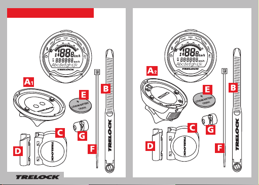
1. Scope of supply
1.1 FC 820, 830, 840
1.2 FC 845
2x
2x
3x
2x
40
Page 5
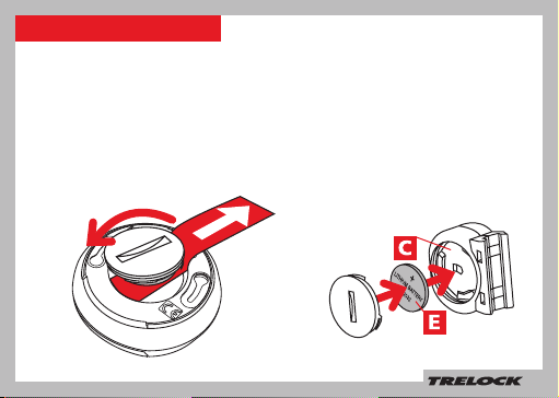
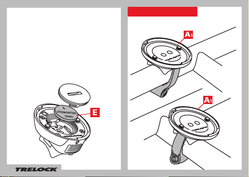
2. Insertion of batterie 2.1 Sensor
When supplied to the customer, the
battery has already been inserted into the
bike computer. In order to activate the
computer, the red plastic fl ag must fi rst be
removed. Turn the battery compartment
cap on the bottom of the computer in an
anti-clockwise direction and pull the fl ag
out. Then turn the cap fi rmly back in place.
In order to insert this battery, use a coin
to turn the battery compartment cap in
an anti-clockwise direction and insert
the battery with the + sign pointing
upwards (see fi g.). Then turn the cap
fi rmly back in place.
Lithium Battery CR2032
Lithium Battery CR2032
41
Page 6
2.2 Only FC 845
The display for your bike computer is fed
via a battery in the night-light base. In order to insert this battery, use a coin to turn
the battery compartment cap in an anticlockwise direction and insert the battery
with the + sign pointing upwards (see fi g.).
Then turn the cap fi rmly back in place.
Lithium Battery CR2032
42
3. Assembly/Installation
3.1 Assembly/Installation FC 820, 830, 840
a) Handlebar
b) Frame
Page 7
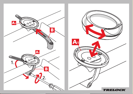
3.2 FC 820, 830, 840
43
Page 8
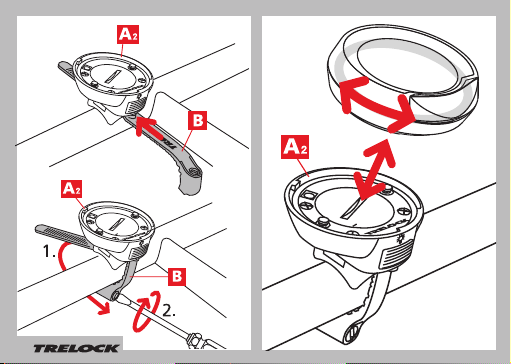
3.3 FC 845
44
Page 9
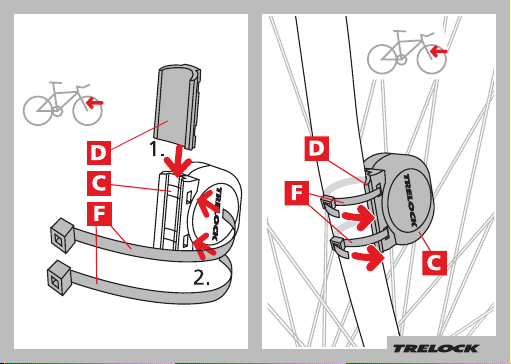
3.4 Assembly/Installation of sensor
45
Page 10
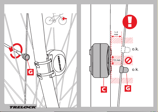
3.5 Assembly/Installation of magnet
46
Page 11
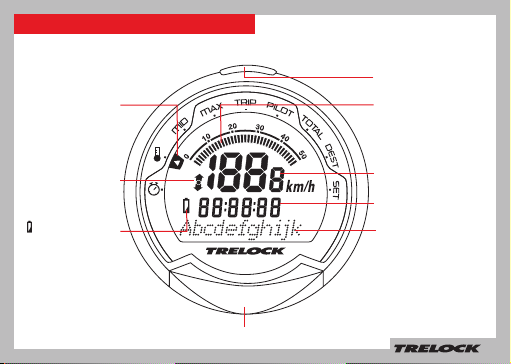
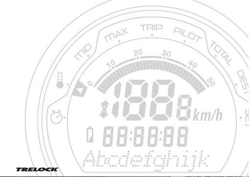
4. Display design and operating principle
Visual guidance
system
SET-button
Analogue speedometer
display
Comparison of
current speed with
average speed
Change battery
MODE button
Display line 1
Display line 2
Display line 3
47
Page 12

5. General default settings
5.1 Selection of language
Once the computer (by removing the plastic
tab) has been activated, you automatically
access the “Sprache?” (Language) menu. By
pressing the SET button, you access the language selection option. Use the MODE button
to choose one of the eight languages shown
(German, English, French, Dutch, Spanish,
Italian, Russian or Polish) and confi rm your
choice via the SET button.
48
Page 13

49
Page 14

5.2 Choice between km/h
and m/h
In the “Dimensions?” menu, “km/h”
is pre-set as the standard unit. If
you wish to accept this default
setting, press the MODE button.
To change it to “m/h”, press the
SET button. Then use the MODE
button to choose between “m/h”
and “km/h” in the “Unit Speed”
window. Confi rm your choice via
the SET button.
50
Page 15

5.3 Choice between °C and °F
(only FC 840, 845 )
Use the MODE button to choose
between ”°F“ and ”°C“ now.
Confi rm your choice via the SET
button.
51
Page 16

5.4 Setting(s) of wheel size(s)
(FC 830, 840, 845 )
You can use your cycle computer
on 2 cycles – even if the wheels are
different sizes. To do this, you need a
separate holder and sensor for each
cycle. For FC 830/840, you need Art.
ZF 406 Uni-Base, ZF 435 transmitter,
ZF 50 magnet. For FC 845 you will
need Art. ZF 410 Night-LightBase +
magnet, ZF 435 transmitter. Press the
SET button to make or change the
settings for cycle 1 or cycle 2 in the
“Settings for cycle” window. Use the
MODE button to select “Cycle 1” or
“Cycle 2”, then press the SET button
to confi rm.
52
Page 17

5.5 Entering the code number
In the “Code No. 1” bzw. “Code
No. 2” window, enter the 4-digit
code of the sensor to register this
on the computer. Smooth, uninterrupted communication between
the computer and the sensor
is assured by the Radio Select
technology only once the sensor is
registered. If the cycle or computer
is stolen, the computer is of no use
to the thief.
You will fi nd the code number on
a peel-off sticker on the sensor.
You should remove the sticker and
stick it in the instruction manual.
Press the MODE button repeatedly until the fi rst digit has been
correctly entered, then press the
SET button to confi rm. Repeat
the procedure for the each of the
other digits.
53
Page 18

5.6 Setting(s) of wheel size(s)
(wheel circumference)
Under “Wheel Size 1” or “Wheel Size
2” (only for FC 830, 840 845), you
should now enter the wheel circumference of your bike. This can be
seen from the wheel size data shown
on the side of your tyre. Please
consult the table shown on P. 55 for
the appropriate 4-digit number.
Next press the MODE button until
such time as the appropriate digit
appears, then use the SET button
to move to the next digit. Once you
have confi rmed the fi nal digit, you
automatically reaccess the “Set
Wheel” window. Should you wish
to make settings for a second bike,
press the SET button, otherwise
move to the “Clock” window by
pressing the MODE button.
54
Wheel size (mm) =
2 x r (mm) x 3,14
1 inch = 25,4 mm
Page 19

Wheel Size (WS) Chart (wheel sizes / wheel circumference)
ETRTO WS mm
47 – 305 16x1.75x2 1272
47 – 406 20x1.75x2 1590
50 – 406 20/2.00 1593
60 – 406 20/2.35 1665
37 – 540 24x1 3/8 A 1948
47 – 507 24x1.75x2 1907
50 – 507 24/2.00 1910
40 – 559 26x1.5 2026
44 – 559 26x1.6 2051
47 – 559 26x1.75x2 2074
50 – 559 26x1.9 2089
54 – 559 26x2.00 2114
57 – 559 26x2.125 2133
37 – 590 26x1 3/8 2105
20 – 571 26x3/4 1954
ETRTO WS mm
60 – 559 26/2.35 2146
32 – 630 27x1 1/4 2199
40 – 622 28x1.5 2224
47 – 622 28x1.75 2268
40 – 635 28x1 1/2 2265
37 – 622 28x1 3/8x1 5/8 2205
18 – 622 700x18C 2102
23 – 622 700x23C 2133
25 – 622 700x25C 2146
28 – 622 700x28C 2149
32 – 622 700x32C 2174
37 – 622 700x35C 2205
40 – 622 700x40C 2224
50 – 622 28/2.00 2284
60 – 622 28/2.35 2340
55
Page 20

5.7 Setting the current time
If you wish to change the time,
press the SET button. One
after another, hours, minutes and
seconds (start automatically after
confi rmation of minutes) can be
changed via the MODE button. Use
the SET button to confi rm your entries and to move to the next digit.
56
Page 21

5.8 Entering and changing the PIN anti-theft protection
You can use a PIN to protect your cycle computer from misuse
by unauthorized people. The cycle computer cannot be used
unless the correct PIN is entered. Once the time has been set,
you automatically access the “Change PIN?” window. Here you
can enter your own PIN and, if necessary, subsequently change
it. If you don’t wish to use a PIN, press the MODE button. Otherwise, after pressing the SET button, you will be asked to enter
the old PIN (default setting is “0000“). To this end, press the
MODE button until such time as the appropriate digit appears
and then use the SET button to move to the next digit. PIN input
is monitored. Should the PIN have been entered incorrectly, the
message “Wrong PIN” appears for approx. 3 seconds and you
will be asked to re-enter the PIN. If the PIN is correct, input a
new PIN of your choice as described above. Once the last digit
has been confi rmed via the SET button, PIN entry must be repeated. Should the repeat PIN entry be incorrect, you will return
automatically to the “Change PIN?” window.
personal PIN on Page 68 so that it is readily available if required!
Note down your
57
Page 22

5.9 Entering and changing the PIN time
If the bike computer is in Sleep mode and is not ‘awakened’ for a
set time, it has to be reactivated by entering your PIN. The period
concerned (PIN Time) can be (re)set in the “Set PIN Time” window
– after you have pressed the SET button, you will be asked to
enter your PIN. After correct PIN input, you automatically access
“PIN Time” where you can enter the time of your choice up to max.
240 minutes. If you wish to dispense with the securing of your bike
computer via a PIN, then set the PIN time to “000”.
58
Page 23

5.10 Energy economy function
An energy economy function is linked to
the PIN-time setting. The PIN-time default
setting is 60 min. and the PIN default setting
“0000”. As such, the clock is displayed in
Sleep for 60 min., after which time the clock
display shuts down. This period of time can
be adjusted as described above. If the PIN
time is set at 0, the energy economy function
is deactivated and the clock is displayed on
an ongoing basis.
If a PIN is set at “0000” and a PIN time at
more than 0, the energy economy function
and the PIN enquiry are activated. This
means that, once the PIN time has elapsed,
the clock display shuts down and the computer can only be reactivated via PIN input.
6. Main menus
Press the MODE button to move between
the main functions (menus) - see 6.1 - 6.9.
To enter fi gures (time, counter settings, etc.),
repeatedly press the MODE button until the
digit you want is displayed, then press the SET
button to move on to the next digit. When you
have completed your entry of the last digit,
press the SET button to confi rm.
59
Page 24

6.1 „Stopwatch” menu
(only FC 530, 535 )
Current speed
Stopwatch
Menu display
6.2 “Temperature“ menu (only FC 840, 845 )
The Temperature “ “ menu displays the current
temperature.
60
Starting, stopping and resetting the
stopwatch
Use the SET button
to start and stop the
stopwatch.
By pressing and holding
the SET button for 3
seconds, the stopwatch
is reset to “0”.
Current speed
Current time
Current temperature
Page 25

6.3 “Average” MID menu
The “MID“ menu shows the current average
speed of the given lap.
By pressing and holding the SET button for
3 seconds, you stop the measurement of the
current lap and reset all lap readings on the
computer to “0”.
Current speed
Current time
Average speed
of the current lap
6.4
“Maximum” MAX menu
Current speed
Current time
Maximum speed
on current lap
The maximum speed on the given lap is
displayed via the “MAX” menu.
By pressing and holding the SET button for
3 seconds, you stop the measurement of the
current lap and reset all lap readings on the
computer to “0”.
61
Page 26

6.5 “Lap” TRIP menu
Current speed
Lap ride rime
Lap kilometres
ridden
The ride time and lap kilometres ridden are
displayed via the “TRIP” menu.
By pressing and holding the SET button for
3 seconds, you stop the measurement of the
current lap and reset all lap readings on the
computer to “0”.
6.6 “Pilot” PILOT menu
62
Current speed
Current time
Day kilometre counter (adjustable)
Setting of day kilometre counter
By pressing and holding the SET button for 3
seconds, you can change the display of the
day kilometre counter in the “Set km” window
(only possible with deactivated stopwatch). This
function is helpful if you have made a detour, for
instance, despite the fact that you are otherwise
following a road book.
Page 27

3 seconds
6.7 “Total” TOTAL menu
Current speed
Total ride time
(of current bike)
Total kilometres of
current bike
The total kilometre status and total ride time of the
current bike are displayed via the “Total” menu.
The total kilometre status can be adjusted via the
“Set” menu, enabling you, for instance, to transfer the
kilometre reading from an old bike computer to your new
TRELOCK computer.
63
Page 28

6.8 “ DEST” menu (only FC 840, 845)
Current speed
Remaining journey time (calculated
from the remaining distance and
the average speed measured to the
relevant point)
Remaining distance in kilometres
(Countdown)
Setting the remaining distance counter
(Countdown)
Press and hold the SET button for 3 seconds.
You can now set the remaining distance counter
in “Set km”. Use the MODE button to set the fi rst
digit, then press the SET button to move on to
the next digit and to confi rm.
64
3 seconds
set km
Page 29

6.9 “Set” SET menu
Changing the presetting
Current speed
Total ride time
(for Bikes 1+ 2)
Total kilometres
(for Bikes 1+ 2)
If you use your computer on 2 cycles (not
applicable to FC 820), the cycle on which the
computer is mounted is automatically detected
(Radio Select).
By pressing and holding the SET button in the
“SET” menu for 3 seconds, you then have the
option of correcting your default settings and
making further settings. Pressing the MODE button
brings you automatically to the menus “Clock?”
“Wheel Size?” with its submenus “Bike 1” and
“Bike 2” (not applicable to FC 820) and “T otal
km” one after the other. Press the SET and MODE
buttons simultaneously for 3 seconds to move to
the general default settings (P. 48, Point 5.1.ff).
65
Page 30

7. Training
7.1 Targeted training
Your TRELOCK bike computer gives you a
wide range of options for training in a targeted
manner. You have the possibility, for example,
of monitoring
• how long you train for
• how many kilometres you cover
• how long you need to cover a certain distance.
Via the symbols „▲“, „●“ and „▼“ on the
display, you are able to monitor the intensity of
your training session on an ongoing basis.
▲ = the current speed is higher than the
average speed on the current lap/stage
● = the current speed equates to the average
speed on the current lap/stage
▼ = the current speed is lower than the
average speed on the current lap/stage.
66
8.
Additional information and instructions
8.1 Battery change
= When this symbol appears, the battery
needs changing.
The bike computer, the sensor and the
night-light base (only FC 845) run on 3-V CR
2032-type batteries.
Caution - old batteries are special waste and
may not be disposed of via household waste!
Your personal data continues to be stored
even if there is no battery in your bike
computer.
9.3 Resets
Any resets that may be necessary are carried
out automatically. Should a fault nevertheless
occur, remove the battery from the bike
computer, wait briefl y and then reinsert it.
Page 31

8.2 Frequently asked questions
Why can’t the bike computer be activated?
The battery is fl at and must be replaced.
Why isn’t any other current data displayed
apart from the time?
The bike computer is in Sleep mode – just
press any button of your choice or simply
start cycling.
Why is the incorrect speed displayed?
The wrong wheel size has been entered.
Why is no speed displayed?
The distance between the sensor and the
magnet is too large. The sensor battery
is low.
Why does the display go black or react
lethargically?
The operating temperature (5 ˚C – 50 ˚C; 40
˚F – 120 ˚F) has not been reached or has
been exceeded.
Why is the display pale?
The battery is fl at and must be replaced.
8.3 Technical data
Operating temperature: 5 ˚C bis 50 ˚C
(40 ˚F und 120 ˚F)
Storage temperature: –20 ˚C und 80 ˚C
(–4 ˚F und 176 ˚F)
Battery type for
bike computer
and sensors: 3 Volt Lithium
CR 2032
8.4 Maintenance and care
Your TRELOCK bike computer requires no
maintenance and no special care. Just use a
damp cloth for cleaning purposes. Protect the
sensors and receivers from exposure to extreme
temperatures. Temperatures below – 20 ˚C (– 4
˚F) and over 80 ˚C (176 ˚F) can damage the bike
computer. The operating temperature should lie
between 5 ˚C – 50 ˚C (40 ˚F – 120 ˚F).
8.5 Safety instructions
TRELOCK bike computers are designed for
private fi tness training and are unsuitable for
commercial or medical applications.
67
Page 32

8.6 Warranty and service
You have purchased a quality product from
TRELOCK. TRELOCK guarantees the initial
purchaser for a period of two years from the date
of purchase that this TRELOCK product is free of
defects in respect of materials and workmanship,
and ensures that any defective product is repaired
or replaced with a new product. Any complaints
you may have should be addressed directly to
your dealer/specialist stockist, who should also
be provided with the relevant purchase receipt. He
will ensure that your warranty entitlement case is
handled correctly. The warranty is only valid providing the product has not been forcibly opened
or damaged. It does not apply for batteries and
such parts as are subject to wear and tear. Under
the terms of this warranty, TRELOCK cannot be
made liable for any damage occurring due to
product defects of any kind whatsoever. Other
legal entitlements in respect of defects remain
unaffected by this warranty. Any questions you
may have can also be addressed to TRELOCK’s
customer service department:
TRELOCK GmbH, Postfach 7880, 48042 Münster,
Germany, www.trelock.de.
68
Here you can enter your PIN numbers
PIN
Default PIN setting:
0 0 0 0
My personal PIN:
PIN-time
Default PIN-time setting:
0 6 0
My personal PIN time:
PIN
Page 33

Notes
69
Page 34

Page 35

www.trelock.de
138
 Loading...