

Page 1

E.1
Radar &
Radar Alt
Page 2

E.2
E.3
Congratulations for purchasing a Trek cycling computer.
Page 3

E.3
Please read this instruction manual carefully
and save it for future reference.
Cycling Functions-
Center Display (always displayed)
Current Speed (Fig. 1)- 0.0-99.9MI or 0.0-
160KM, updated every second.
Pacer (Fig. 2)- compares
current speed to average
speed. Arrow Up (shown)
shows current speed equal or
greater than average. Arrow
Down indicates current speed
is less than average speed.
Temperature (Fig. 3). Air
Do not stare at your computer while riding.
Ignoring obstacles in your path may cause
loss of control resulting in personal injury.
WARNING
Fig. 1
Fig. 2
© Copyright Trek Bicycle Corporation 2001 All rights reserved
Page 4

E.4
E.5
temperature, displayed in
Fahrenheit or Celsius to correspond to user’s selection of
miles or kilometers.
Wind chill (Fig. 4). Calculates temperature with speed.
Starts at 50°F with ten degree
increments to -20°F.
Upper Display (scroll with Set
button)
SET button (Fig. 5). Used
to scroll through features on
upper screen lines. Also used
in Reset of computer, referred
to as <SET>.
RIDE TM - Ride Time (Fig.
6) 99:59:59 maximum hours.
Time since Start or ReSet,
displayed in MM:SS for rst
hour (SS ashes), then HH:MM.
Begins counting automatically
when computer receives signal
Fig. 3
Fig. 6
Fig. 5
Fig. 4
Page 5

E.5
that wheel is turning, turns off
after 2 seconds of no signal.
Rollover to zero after 100 hours
(which also resets AVG SPD, TRP
DST, and MAX SPD).
DAY/DT- Today’s date (Fig.
7)- three letter day of the week,
two digit date.
TIME- Clock (Fig. 8) showing time of day expressed in 12
or 24 hour format.
Compass (Fig. 9), Radar
ALT model only. One or two
letter compass heading (N,
NE, E, etc.). The compass icon
always points east.
Backlight (Fig. 10), Press
left button to illuminate the
display. Light turns off automatically in ve seconds.
Lower Line (scroll with Mode
Fig. 7
Fig. 9
Fig. 8
Fig. 10
Page 6

E.6
E.7
button)
MODE button (Fig.
11). Used to scroll through
features on lower screen
lines. Also used in Reset of
computer, referred to as
<MODE>.
TRP DST - Trip Distance
(Fig. 12). Maximum 9999.9KM
or 6213.0MI), then rollover to
zero. Automatically calculated
since Start or ReSet.
ODOMTR - Odometer (Fig. 13). Programmable,
cumulative distance with maximum mileage of
62130MI or 99999KM. Continuously measured and
accumulated. Rollover to zero when maximum
mileage is reached. Sets to zero when ReStart
or ReSet is performed, or the
battery is changed.
Fig. 11
Fig. 12
Fig. 13
Page 7

E.7
AVG SPD - Average Speed
(Fig. 14). TRP DST divided by
RIDE TM. Minimum display of
0.1. Calculated since last Start,
ReSet, ride time rollover, or
battery change.
MAX SPD - Maximum Speed
(Fig. 15). 100.0MPH or 160.7KPH
maximum. Calculated since last
Start, ReSet, ride time rollover,
or battery change.
Fig. 14
Fig. 15
Page 8
E.8
E.9
Additional Features-
6 Language scroll bar for easy usage
Waterproof
Auto Start/Stop/Sleep - Computer turns on
automatically when wheel turns. Enters Sleep
mode after 2 seconds of no signal to preserve
average speed. Time continues to display when
the computer is in sleep mode.
To save battery life, the computer turns off
automatically after 10 minutes of no signal, or 10
minutes of sleep mode.
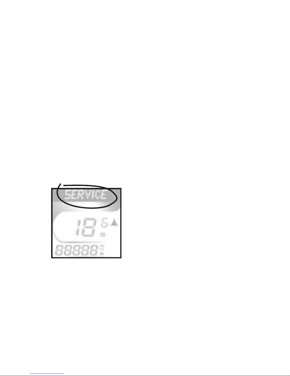
Service Alert (Fig. 17) -
to keep the bike running
smooth, a Service reminder
comes on after the rst 300
miles, and at every 1000 miles
thereafter. Check your bicycle
Owner’s Manual for a detailed
maintenance schedule. To turn
off the alert, push any button.
Fig. 17
Page 9

E.9
Install the computer on your bike
Install the Sensor and Magnet
1. Position the sensor unit to the inside of
the right fork blade near the top (Fig. 18). NOTE:
For best results computer and sensor should be
less than 18” apart. Attach the sensor to the fork
blade with quick ties, but do
not tighten the ties yet.
2. Attach the wheel
magnet to the spoke, aligning
the magnet with the sensor
(Fig. 19). The magnet should
have 3-5 mm clearance from
the sensor. If the sensor
and magnet are too close, or
touching, rotate the sensor
unit away from the magnet
until adequate clearance is
achieved.
3. Once correct orientation is achieved, tighten
the sensor attachment quick ties and tighten
the magnet. Trim excess quick tie length with a
Fig. 18
Fig. 19
Page 10
E.10
E.11
scissors.
4. Attach the bracket to
the handlebar, on the righthand side of the stem. Position
the bracket end with the
Phillips head screw nearest
the rider (Fig. 20).
Your computer comes with a bar clamp which ts both 25.4
and 26.0mm diameter (mountain or road) handlebars. If your
handlebar has a 31.8mm diameter, purchase the special clamp
from your dealer.
Attach the Computer to the Handlebar Bracket
From in front of the handlebars, slide the
computer back onto the bracket until it snaps
rmly into position.
5. To remove the computer from the bracket
push the computer away from you with your thumb,
with your index nger against the back of the
Fig. 20
Page 11

E.11
mounting bracket for support (Fig. 20).
Calibrate the Computer
Quick Set-Up
Your Trek Computer has a preset wheel size
(as marked on the box) and is ready to ride.
The next section describes how to change the factory settings.
Follow those instructions which cover the setting(s) you would
like to change.
“Press” means briey push the button once.
“Hold” means continuously hold the button in the depressed position until the computer responds as desired.
Set Wheel Size-
Selecting the size of tire on your bike will provide a high level of
accuracy. If you desire a wheel size not offered in the standard
menu (below), see “Set Custom Wheel Size” on page 16.
700x20 26x1.50 650x23 CUSTOM
700x23 26x1.90 650x25
700x25 26x1.95
700x32 26x2.0
700x35 26x2.1
700x38
1. Press <Set> (Fig. 3) until the RIDE TM screen
appears on the upper line of the display.
2. Hold <Set> until SET WHL is displayed.
3. Press <Mode> (Fig. 11) to scroll to a different setting. Press <Set> to select your preferred
wheel size.
After selection is made with <Set>, DONE displays, then the
computer returns to normal operation.
Page 12

E.12
E.13
Dual wheel Size selection and set up.
In any mode (day/date, time, compass, ride time)
press and hold Mode and Set for 2 seconds.
The computer will toggle between Wheel size 1
and Wheel size 2 in the lower right corner of the
screen (Fig 20a). Lock in choice by releasing Mode
and Set button when desired
wheel is on screen.
Set-up-wheel size for second wheel follow steps 1 –3
1. Press <Set> until the RIDE TM
screen appears on the upper line of
the display.
2. Hold <Set> until SET WHL is displayed.
3. Press <Mode> to scroll to a
different setting. Press <Set> to select your
preferred wheel size.
After selection is made with <Set>, DONE displays, then the
computer returns to normal operation.
Fig. 20a
Page 13

E.13
Set Day and Date
1. Press <Set> to scroll to DAY/DT.
2. Hold <Set> until SET DT displays, replaced
by a two digit display, with a digit ashing.
3. Press <Mode> to scroll the number menu.
4. Press <Set> to select a number and
advance to the next digit.
5. Repeat #3 and 4. SET MTH displays, and the
Month menu appears.
6. Repeat #3 and 4 for to select a month. SET
YR displays, replaced with a four-digit number with a
digit ashing.
7. Repeat #3 and #4 for both digits.
After selection is made with <Set>, DONE displays, then the
computer returns to normal operation.
Set Time or Set Alarm-
1. Press <Set> to scroll to TIME.
2. Hold <Set> until SET TME displays. Press
<Mode> to scroll to SET TME or SET ALM.
3. Press <Set> to choose. SET HR displays,
then shows 2 digits with one ashing.
4. Press <Mode> to scroll the number menu.
5. Press <Set> to select a number and
advance to the next digit.
6. Repeat #4 and #5 to set each digit of
Page 14

E.14
E.15
hours. SET MIN displays.
7. Repeat #4 and #5 to set both digits or
minutes. 24 HRS displays.
8. Press <Mode> to scroll clock types 24HR
and 12HR. Press <Set> to choose.
After selection is made with <Set>, DONE displays, then the
computer returns to normal operation.
Set the Odometer -
1. Press <Mode> to scroll to ODOMTR.
2. Hold <Mode> until SET ODO displays, and
the rst digit ashes.
3. Press <Mode> to scroll digits.
4. Press <Set> to select a number and
advance to the next digit.
5. Repeat #4 and #5 to set each digit of
Odometer.
After selection is made with <Set>, DONE displays, then the
computer returns to normal operation.
Set KM/MI-
1. Press <Mode> to scroll to MAX SPD.
2. Immediately hold <Mode> to toggle
between each choice. SET M/KM displays, then MI.
Push <Mode> to scroll between MI and KM.
3. Press <Set> to select.
After selection is made with <Set>, DONE displays, then the
Page 15

E.15
computer returns to normal operation.
ReSet (Ride Memory)-
Your computer has Ride Memory that calculates and stores Trip
Distance, Average Speed, Maximum Speed, and Ride Time. This
data can be reset to zero, and the computer will automatically
begin storing data again.
1. In any mode, simultaneously press <Mode>
and <Set>.
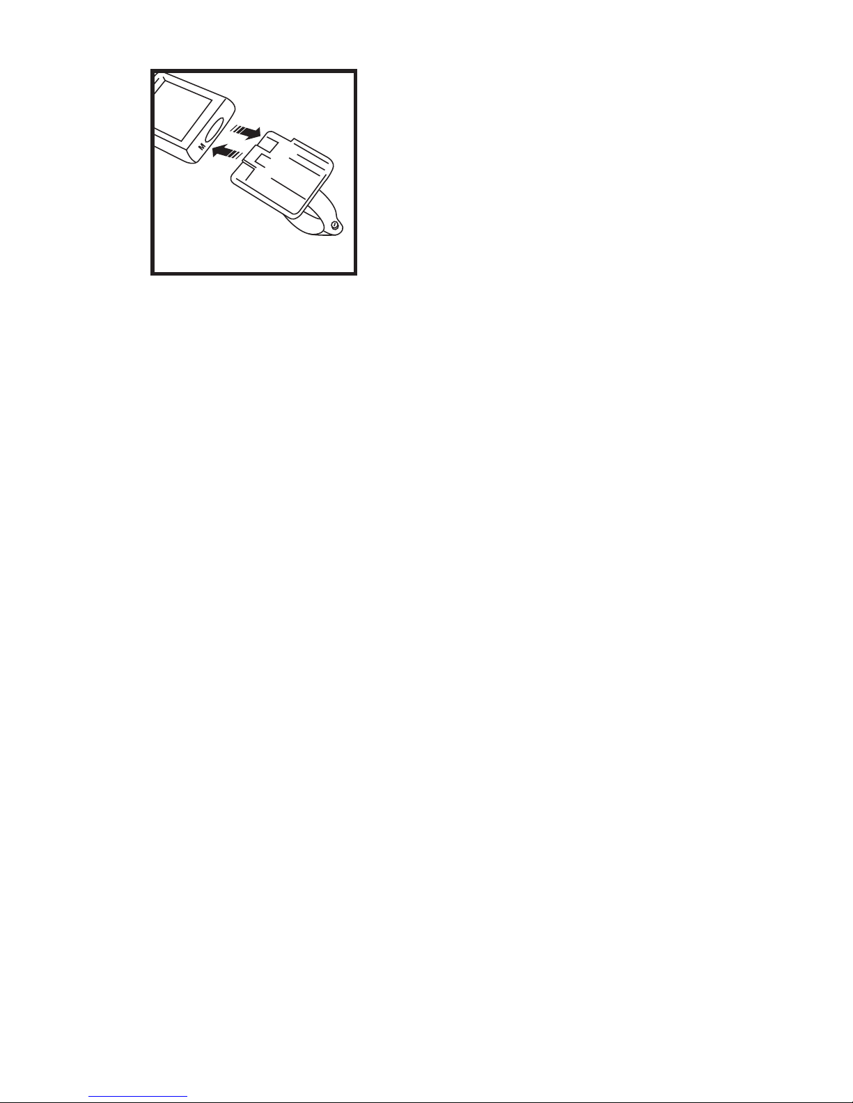
Install Battery-
1. Remove the computer from the handlebar
bracket.
2. Turn the computer in your hand so the
display faces down. With a coin or similar object,
rotate the battery cover on the
back of the computer (Fig. 21).
3. After about 1/2 turn, the
cover can be removed. Turn the
computer over so the display is
face-up. Catch the parts in your
hand as the cover and battery
falls out.
4. Turn the computer
display face-down. Place the
battery into the computer with
the positive “+” side visible
(Fig. 22).
5. Replace the battery
cover by pressing it rmly into
Fig. 21
+
Fig. 22
Page 16
E.16
E.17
place with your thumb or ngers.
6. Follow the instructions on page 14 to
ReStart after installing a battery.
First Use- after ReStart or Battery Install
1. ENG displays. Press <Mode> to scroll the
language options.
2. Press <Set> to select. SET WHL displays,
then a wheel size.
3. Press <Mode> to scroll wheel sizes.
4. Press <Set> to select wheel size see page 11 for
Custom option). SET M/KM dispays, followed by MI.
5. Press <Mode> to scroll between MI and KM.
6. Press <Set> to choose.
After selection is made with <Set>, DONE displays, then the
computer returns to normal operation.
Set Custom Wheel Size (optional)
Determine the actual Wheel Size
A rollout test determines the actual wheel circumference for
computer calibration. Perform the
roll-out test on a hard, at surface such
as a garage or basement oor.
Make sure the tires are properly
inated. For the highest level of
accuracy, the rider should be on the
bike during roll-out.
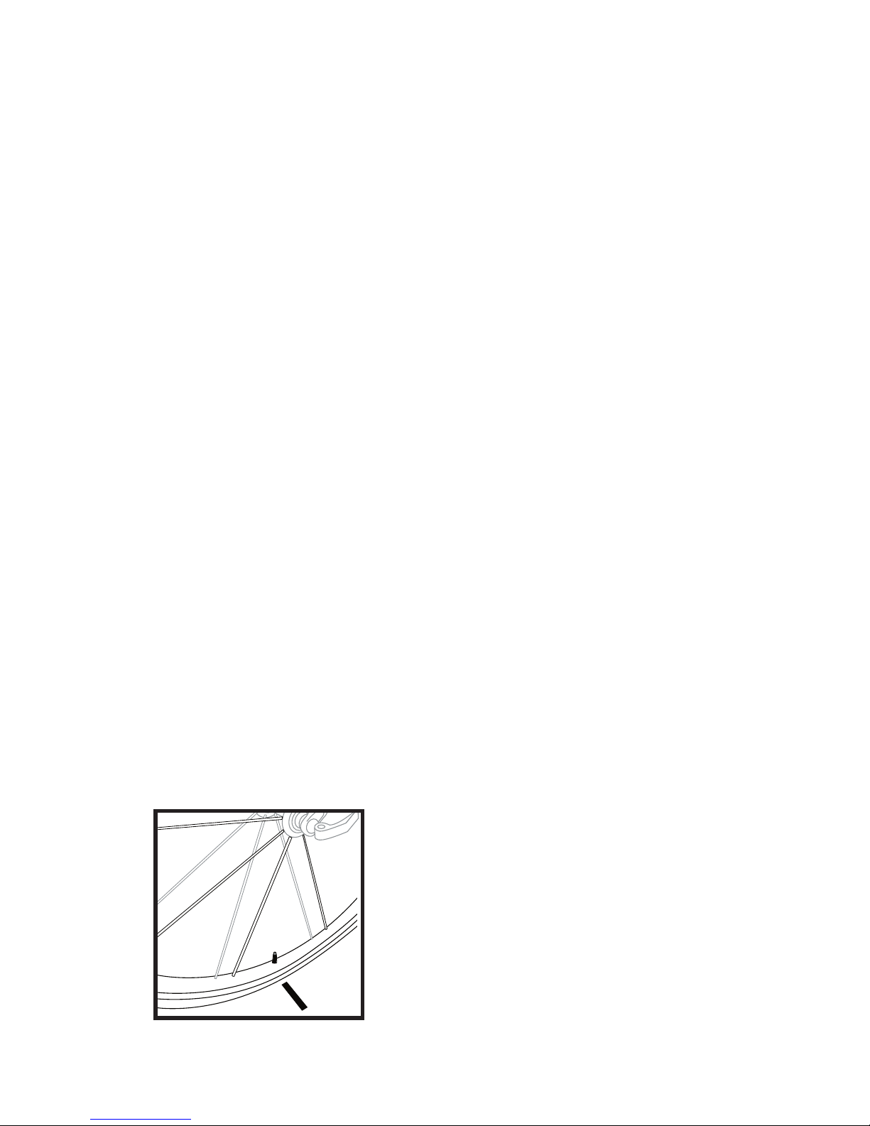
1. Position the bike so
that the front wheel valve
�
Fig. 23
Page 17

E.17
stem is at its bottom-most position.
2. Mark the ground directly under the valve
stem with chalk or a piece of tape (Fig. 23).
3. Roll the bicycle forward in a straight line
until the wheel has completed one revolution and
the valve stem is again at its bottom-most position. Make another mark, as before.
4. Measure the distance between the two
marks. Record your measurement in mm_________.
This is your wheel calibration setting.
Note: 1 inch = 25.4mm
Calibrate the computer with Custom Wheel size
5. Follow “Set Wheel Size” on page 11 until
CUSTOM appears in the menu.
6. Hold <Set> until the 4 digit wheel setting is
displayed with the rst digit ashing.
7. Press <Mode> to scroll the ashing digit.
8. Press <Set> to select a number and
advance to the next digit.
9. Repeat #2 and #3 to set each digit.
When <Set> is pressed after the last digit selection, the display
returns to the Mode menu.
Page 18

E.18
ReStart (total system erase)
1. Press All Clear on the
back of the computer (Fig.
24) to erase all information
including wheel size.
Please note your settings before
performing this operation.
Fig. 24
 Loading...