

Page 1

TREK-725
Vehicle Mounted Terminal with
Intel XScale IXP420 533MHz,
WinCE 5.0 and 10.4” TFT LCD
User Manual
Page 2

Copyright
This document is copyrighted, © 2005. All rights are reserved. The original manufacturer reserves the right to make improvements to the products
described in this manual at any time without notice.
No part of this manual may be reproduced, copied, translated or transmitted in any form or by any means without the prior written permission of
the original manufacturer. Information provided in this manual is
intended to be accurate and reliable. However, the original manufacturer
assumes no responsibility for its use, nor for any infringements upon the
rights of third parties that may result from such use.
Acknowledgements
IBM, PC/AT, PS/2 and VGA are trademarks of International Business
Machines Corporation.
Intel® is trademark of Intel Corporation.
Microsoft® Windows® CE.NET is a registered trademark of Microsoft
Corp.
All other product names or trademarks are properties of their respective
owners.
For more information on this and other Advantech products, please visit
our websites at: http://www.advantech.com
http://www.advantech.com.tw
For technical support and service, please visit our support website at:
http://service.advantech.com.tw/eservice
This manual is for the TREK-725
Part No.
Printed in Taiwan August 2005
Trek-725 User Manual ii
2006720000 1st. Edition
Page 3

FCC Class B
This equipment has been tested and found to comply with the limits for a
Class B digital device, pursuant to Part 15 of the FCC Rules. These limits
are designed to provide reasonable protection against harmful interference when the equipment is operated in a residential environment. This
equipment generates, uses and can radiate radio frequency energy. If not
installed and used in accordance with this user's manual, it may cause
harmful interference to radio communications. Note that even when this
equipment is installed and used in accordance with this user's manual,
there is still no guarantee that interference will not occur. If this equipment is believed to be causing harmful interference to radio or television
reception, this can be determined by turning the equipment on and off. If
interference is occurring, the user is encouraged to try to correct the interference by one or more of the following measures:
• Reorient or relocate the receiving antenna
• Increase the separation between the equipment and the receiver
• Connect the equipment to a power outlet on a circuit different from that
to which the receiver is connected
• Consult the dealer or an experienced radio/TV technician for help
Warning! Any changes or modifications made to the
equipment which are not expressly approved by
the relevant standards authority could void your
authority to operate the equipment.
iii
Page 4

Packing List
Before you begin installing your card, please make sure that the following
materials have been shipped:
• l TREK-725 series Vehicle Mounted Terminal
• l Accessories for TREK-725
• Advantech Software Support CD (Windows® CE.NET)
- Readme.txt
- Datasheet
- User manual
- Windows® CE .NET 5.0 platforms SDK (for Windows® CE .NET)
- Microsoft ActiveSync Version 3.7 installs files (for Windows® CE
.NET)
• W ater-proof DC power inlet cable
• USB client ActiveSync cable
• End User License Agreement (for Windows® CE version)
• Warranty card
If any of these items are missing or damaged, contact your distributor or
sales representative immediately.
Trek-725 User Manual iv
Page 5

Additional Information and Assistance
Step 1. Visit the Advantech web site at www.advantech.com or
www.advantech.com.tw where you can find the latest informa-
tion about the product.
Step 2. Contact your distributor, sales representative, or Advantech's cus-
tomer service center for technical support if you need additional
assistance. Please have the following information ready before
you call:
• Product name and serial number
• Description of your peripheral attachments
• Description of your software (operating system, version,
application software, etc.)
• A complete description of the problem
• The exact wording of any error messages
Warning!
1. Input voltage rated:
default 24-48Vdc, optional 12Vdc
2. Use a 3 V @ 65 mA lithium battery
3. Packing: please carry the unit with both hands, handle
with care
4. Maintenance: to properly maintain and clean the surfaces, use only approved products or clean with a dry
applicator
5. CompactFlash: Turn off power before inserting or
removing CompactFlash storage cards.
v
Page 6

Safety Instructions
1. Read these safety instructions carefully.
2. Keep this user manual for later reference.
3. Disconnect this equipment from any AC outlet before cleaning. Use a damp
cloth. Do not use liquid or spray detergents for cleaning.
4. For plug-in equipment, the power outlet socket must be located near the
equipment and must be easily accessible.
5. Keep this equipment away from humidity.
6. Put this equipment on a reliable surface during installation. Dropping it or letting it fall may cause damage.
7. The openings on the enclosure are for air convection. Protect the equipment
from overheating. DO NOT COVER THE OPENINGS.
8. Make sure the voltage of the power source is correct before connecting the
equipment to the power outlet.
9. Position the power cord so that people cannot step on it. Do no t place anything
over the power cord.
10. All cautions and warnings on the equipment should be noted.
11. If the equipment is not used for a long time, disconnect it from the power
source to avoid damage by transient overvoltage.
12. Never pour any liquid into an opening. This may cause fire or electrical shock.
13. Never open the equipment. For safety reasons, the equipment should be
opened only by qualified service personnel.
14. If one of the following situations arises, get the equipment checked by service
personnel:
a. The power cord or plug is damaged.
b. Liquid has penetrated into the equipment.
c. The equipment has been exposed to moisture.
d. The equipment does not work well, or you cannot get it to work according
to the user's manual.
e. The equipment has been dropped and damaged.
f. The equipment has obvious signs of breakage.
2. DO NOT LEAVE THIS EQUIPMENT IN AN ENVIRONMENT WHERE
THE STORAGE TEMPERATURE MAY GO BELOW -20° C (-4° F) OR
ABOVE 60° C (140° F). THIS COULD DAMAGE THE EQUIPMENT . THE
EQUIPMENT SHOULD BE IN A CONTROLLED ENVIRONMENT.
3. CAUTION: DANGER OF EXPLOSION IF BATTERY IS INCORRECTLY
REPLACED.REPLACE ONLY WITH THE SAME OR EQUIVALENT
TYPE RECOMMENDED BY THE MANUFACTURER, DISCARD USED
BATTERIES ACCORDING TO THE MANUFACTURER'S INSTRUCTIONS.
The sound pressure level at the operator's position according to IEC 704-1:1982 is
no more than 70 dB (A).
DISCLAIMER: This set of instructions is given according to IEC 704-1. Advantech disclaims all responsibility for the accuracy of any statements contained
herein.
Trek-725 User Manual vi
Page 7

Wichtige Sicherheishinweise
1. Bitte lesen sie Sich diese Hinweise sorgfältig durch.
2. Heben Sie diese Anleitung für den späteren Gebrauch auf.
3. Vor jedem Reinigen ist das Gerät vom Stromnetz zu trennen. Verwenden Sie
Keine Flüssig-oder Aerosolreiniger . Am besten dient ein angefeuchtetes Tuch
zur Reinigung.
4. Die NetzanschluBsteckdose soll nahe dem Gerät angebracht und leicht
zugänglich sein.
5. Das Gerät ist vor Feuchtigkeit zu schützen.
6. Bei der Aufstellung des Gerätes ist auf sicheren Stand zu achten. Ein Kippen
oder Fallen könnte Verletzungen hervorrufen.
7. Die Belüftungsöffnungen dienen zur Luftzirkulation die das Gerät vor überhitzung schützt. Sorgen Sie dafür , daB diese Öffnungen nicht abgedeckt werden.
8. Beachten Sie beim. AnschluB an das Stromnetz die AnschluBwerte.
9. Verlegen Sie die NetzanschluBleitung so, daB niemand darüber fallen kann.
Es sollte auch nichts auf der Leitung abgestellt werden.
10. Alle Hinweise und Warnungen die sich am Geräten befinden sind zu beachten.
11. Wird das Gerät über einen längeren Zeitraum nicht benutzt, sollten Sie es vom
Stromnetz trennen. Somit wird im Falle einer Überspannung eine Beschädigung vermieden.
12. Durch die Lüftungsöffnungen dürfen niemals Gegenstände oder Flüssigkeiten
in das Gerät gelangen. Dies könnte einen Brand bzw. elektrischen Schlag auslösen.
13. Öffnen Sie niemals das Gerät. Das Gerät darf aus Gründen der elektrischen
Sicherheit nur von authorisiertem Servicepersonal geöffnet werden.
14. Wenn folgende Situationen auftreten ist das Gerät vom Stromnetz zu trennen
und von einer qualifizierten Servicestelle zu überprüfen:
a. Netzkabel oder Netzstecker sind beschädigt.
b. Flüssigkeit ist in das Gerät eingedrungen.
c. Das Gerät war Feuchtigkeit ausgesetzt.
d. Wenn das Gerät nicht der Bedienungsanleitung entsprechend funktioniert
oder Sie mit Hilfe dieser Anleitung keine Verbesserung erzielen.
e. Das Gerät ist gefallen und/oder das Gehäuse ist beschädigt.
f. Wenn das Gerät deutliche Anzeichen eines Defektes aufweist.
2. VOSICHT: Explisionsgefahr bei unsachgemaben Austausch der Batterie.Ersatz nur durch densellben order einem vom Hersteller empfohlenemahnlichen Typ. Entsorgung gebrauchter Batterien navh Angaben des
Herstellers.
Der arbeitsplatzbezogene Schalldruckpegel nach DIN 45 635 Teil 1000
beträgt 70dB(A) oder weiger.
vii
Page 8

DISCLAIMER: This set of instructions is given according to IEC704-1.
Advantech disclaims all responsibility for the accuracy of any statements
contained herein.
Trek-725 User Manual viii
Page 9

Contents
Chapter 1 General Information........................................2
1.1 Introduction.......................................................................2
1.2 General Specifications.......................................................3
1.3 LCD Specifications...........................................................5
1.4 Touch screen Specifications..............................................5
1.5 Power Input Range & Power Consumption......................5
1.6 I/O Ports Placement.......................................................... 6
1.7 Dimensions........................................................................7
Chapter 2 Getting Started...............................................10
2.1 A Quick Tour of the TREK-725 ..................................... 10
2.2 Installation Procedure...................................................... 12
2.2.1 Connecting the Power Cord.................................. ........ 12
2.2.2 Switching On the Power ....... ............................. ........... 12
2.2.3 Calibrate the touch screen............................................. 12
Chapter 3 Hardware and Peripheral Installation.........14
3.1 Overview of Hardware Installation and Upgrading........ 14
3.2 Main Board......................................................................14
3.2.1 Connector Layout ......................................................... 14
3.2.2 Connector Table............................................................ 15
3.3 Charger Board.................................................................16
3.3.1 Connector Layout ......................................................... 16
3.3.2 Connector Table........................................................... 16
3.4 RF communication module installation .......................... 17
3.4.1 Installation of MiniPCI WLAN Card . .. ........................ 18
3.4.2 Installation of GSM/GPRS module ..............................19
3.4.3 Installation of GPS module........................................... 21
3.5 System backup battery module installation..................... 21
3.5.1 Battery Installation........................................................ 22
3.6 Installing the 2.5" Hard Disk Drive (HDD).................... 23
3.7 Placing the Rubber Seal ..................................................25
3.8 Installing the Universal Arm...........................................26
4.1 Introduction.....................................................................28
4.2 Windows CE Startup Procedure......................................29
4.2.1 Setting up HyperTerminal on PC................................. 29
4.2.2 Choosing an image download method.......................... 31
4.2.3 EBOOT configuration examples ................. ................. 36
4.3 Upgrade Procedure......................................... .................36
4.4 Utilities............................................................................38
4.4.1 System Configurator..................................................... 38
ix Table of Contents
Page 10

4.4.2 General.......................................................................... 39
4.4.3 Calibration .................................................................... 40
4.4.4 Display.......................................................................... 42
4.4.5 Watchdog timer............................................................. 43
4.4.6 Miscellaneous ............................................................... 44
4.4.7 Startup execution .......................................................... 45
4.4.8 Hotkey Configuration ................................................... 46
4.5 Network........................................................................... 46
4.5.1 Networking via Ethernet............................................... 46
4.5.2 Networking via PPP...................................................... 47
4.5.3 Web browser................................................................. 48
4.6 M-system DOC Flash File System.................................. 48
4.6.1 Introduction to M-system DOC Flash File System ...... 48
4.6.2 DiskOnChip folder in TREK-725................................. 49
4.7 Application Program Development.................................49
4.7.1 System requirements..................................................... 49
4.7.2 Building programs for Windows CE............................ 50
4.7.3 How to install the SDK....... .......................................... 50
4.7.4 Running your application programs ............................. 54
4.8 TREK-725 Windows® CE 5.0 Default Components ..... 55
4.8.1 Applications and Services Development ...................... 55
4.8.2 Applications – End User............................................... 56
4.8.3 Core OS Services........................... ............................. .. 56
4.8.4 Communication Services and Networking ................... 57
4.8.5 Device Management .................................. ................... 59
4.8.6 File Systems and Data Store ......................................... 60
4.8.7 Fonts.............................................................................. 61
4.8.8 International.................................................................. 62
4.8.9 Internet Client Services................................................. 62
4.8.10 Graphics and Multimedia Technologies....................... 63
4.8.11 Security......................................................................... 65
4.8.12 Shell and User Interface................................................ 65
4.8.13 Windows CE Error Reporting....................................... 66
4.8.14 Voice Over IP Phone Services...................................... 67
4.9 Advantech API Library...................................................67
4.9.1 Update History....... ....................................................... 67
4.9.2 Release notes................................................................. 67
4.9.3 File layout ..................................................................... 68
4.9.4 Application development with this Library.................. 68
4.9.5 Watchdog API............................................................... 69
4.9.6 Get MAC Address API.............................. ................... 71
4.9.7 Adjust Brightness........................... ............................. .. 71
4.9.8 Set Display Resolution............. ............................. .. ...... 73
4.9.9 On/Off Backlight ........................................................ .. 73
4.9.10 Registry flush................................................................ 74
Trek-725 User Manual x
Page 11

4.9.11 Build a Platform with this library ................................. 74
Appendix A Programming the Watchdog Timer .............76
A.1 Programming the Watchdog Timer................................. 76
Appendix B Pin Assignments .............................................80
B.1 CPLD JTAG (JP1) ..........................................................80
B.2 CPU JTAG (JP2).............................................................80
B.3 GPS Adaptor (JP5)..........................................................81
B.4 Inverter Power Connector (CN6).................................... 81
B.5 IDE Hard Disk Drive Connector (IDE1).........................82
B.6 LVDS Connector (CN5).................................................. 83
B.7 Flat Panel Display Connector (CN7) (Reserved)............ 84
B.8 USB Client (CN8 & JP13).............................................. 84
B.9 Touchscreen (CN14).......................................................85
B.10 CAN Bus Connector (CN15) ..........................................85
B.11 GSM/GPRS Adaptor Board Connector (CN16) ............. 86
B.12 COM1 & COM2.................................... .......................... 86
B.13 USB Port ......................................................................... 87
xi Table of Contents
Page 12

Trek-725 User Manual xii
Page 13

CHAPTER
General Information
This chapter gives background Information of the TREK-725 Sections
includes:
• Introduction
• General Specification
• LCD Specification
• Touchscreen Specification
• Power Input Range & Consumption
• I/O Ports Placement
• Dimensions
1
Page 14

Chapter 1 General Information
1.1 Introduction
The TREK-725 Series integrates an Intel XScale IXP 420 ~ 533 MHz
RISC processor and Windows CE .NET 5.0. It is designed to provide customers an in-vehicle panel computer which has good connectivity and a
robust aluminum chassis. In TREK-725, Advantech provides compatible
WLAN, GPRS/GSM, and GPS wireless solutions as well as rich connectivity like CAN bus, COM ports, Ethernet, and USB interfaces. TREK725 also has programmable function keys on the front bezel for customer
application programs and hot-keys for adjusting LCD brightness, backlight on/off, and page up/down functions. In addition, TREK-725 can
operate from input voltages of 24 to 48 Volts for industrial vehicles and
has an optional built-in system backup battery pack which powers TREK725 to work alone for up to 3 hours*. The ultra low power XScale &
WinCE 5.0 combination, good connectivity, robust design, and cost-efficient design makes the TREK-725 an ideal telematics solution for industrial vehicle-based application such as trucks, forklifts, and cranes.
* Battery life time test conditions: no I/O devices or RF modules connected; Only WinCE O.S. running.
Features
• Low power, yet high performance with Intel XScale IXP 420 533MHz
processor
• IP65 fully-sealed rugged aluminum housing with fanless design
• Easy interface access with 4-Wire touch screen
• Customer programmable function keys for flexible application
• Rich industrial I/O interfaces including CAN Bus, COM ports, and
Ethernet
• Optional system backup battery design as a 2nd power source.
• Optional built-in RF modules (GPS/GPRS/GSM/Wi-Fi) with drivers
ready
• Default 24 ~ 48 V power source with 12V optional.
Trek-725 User Manual 2
Page 15

1.2 General Specifications
Table 1.1: General Specifications
System kernel
CPU Intel IXP-420 533MHz on board
OS Windows CE .NET 5.0 Professional Version
SDRAM 64 MB SDRAM on board (extendable to 128 MB or
256 MB)
Flash 32 MB on board for image & customer applications
(extendable to 64 MB)
Buzzer Yes
RTC HT1381 backed up by 65 mAh Rechargeable Li-ion
battery
Display
LCD AUO 10.4" TFT LCD SVGA 800 x 600, 180 nits
Touch Screen Dynapro 4-wire Touch Screen
VGA Chip SM501 with external 8 MB VRAM
I/O
MiniPCI Y es (Driver verified read y for specific Wi-Fi 801.11b/g
module)
PCMCIA 2 x PCMCIA slot type II for CF card / Wi-Fi module
IDE Interface ready for CF slot or 2.5" HDD
CAN Bus 1 x CAN Bus via DB9 connector
COM Port 2 x full function transceiver-level external RS-232
ports (COM1 & COM2 DB9 connectors)
2 x TTL-level internal RS-232 (pin-header), reserved
for GPRS/GSM modules
USB 2 x USB 2.0 Host; 1 x USB 1.1 Client
Ethernet 1 x 10/100Base-T
Function Key 6 x function keys for customer configuration
Hot Key LCD brightness, LCD backlight On/Off, Page up/
down and enter
RF Communication
GPS Default built-in GPS for TREK-725R-GCEA0. The
other models have optional GPS.
GSM/GPRS Optional, please refer section 3.4
WLAN Optional, please refer section 3.4
Audio
Mic-in 1 x Mic-in jack (without record function)
Speaker Out 1 x Speaker out jack
3 Chapter 1
Page 16

Power
Input Range DC 24 ~ 48 V as factory default, 12 V optional
Power Input
Protection
Power Switch 1 x water-proof power on/off switch
Power
Connector
SW reset Yes (through system configurator)
HW reset Yes (push button in back side)
Battery Optional battery pack (4S1P 2200 mAh Li-ion
Mechanical
Dimension 310 x 255 x 80 mm (W x H x D)
Weight 3.5 Kg (Without RF module & battery pack)
Material Aluminum
Environmental
Operating
Temperature
Storage
Temperature
Vibration/
Shock
Water/Dust
resistance
EMC FCC Class A / CE
Safety UL/CE/BSMI/VCCI
Over current protection and reverse pole protection
by 4 A fuse
1 x water-proof power connector
rechargeable type)
0 ~ 50° C (TREK-725R-CEA0)
-30 ~ 50° C (TREK-725R-FCEA0)
-20 ~ 60° C
Random vibration (operation): 1G
Sine vibration (non-operation): 2G
Shock: 50G
IP65/NEMA4 for complete unit (with no I/O cables
connected)
Trek-725 User Manual 4
Page 17

1.3 LCD Specifications
Table 1.2: LCD Specifications
LCD model AU G104SN03
Display type TFT color LCD
Size (Diagonal) 10.4"
Resolution 800 x 600 (VGA)
Maximum colors 262K colors
Pixel pitch (mm) 0.264 (H) x 0.264 (V)
Luminance (cd/m2)
Lamp lifetime 20000 hours
230 cd/m
2
Note: The panel PC uses a reliable, high-quality color LCD display.
However, it may contain a few defective pixels which do not always
illuminate. With current technology, it is impossible to completely eliminate defective pixels. Advantech is actively working to improve this
technology.
1.4 Touch screen Specifications
Table 1.3: Touch screen Specifications
Model DynaPro 95422
Type Resistive
Base glass construction Tempered Glass
Resolution Continuous
Light transmission 75% typical
Durability 1 Million Activations on a single point,
tested by a 5/8" diameter silicone finger
with a 350 g load at 2 Hz.
> 100,000 characters written within a
20 mm x 20 mm area on the touch
screen.
1.5 Power Input Range & Power Consumption
TREK-725 works with a 24 ~ 48V DC power input. The maximum current consumption is about 2 A at 24 Vdc. The power consumption is 20
Watts in normal mode (n o I/O device and RF modules connected to the
TREK-725 with only WinCE O.S. running) and 15Watts in idle mode
(LCD backlight off).
5 Chapter 1
Page 18
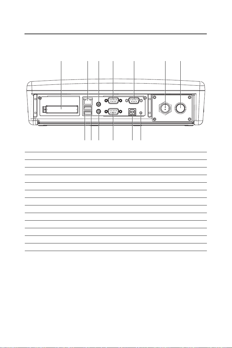
1.6 I/O Ports Placement
12345 67
8 9 10 11 12 13
1 Two PCMCIA slots
2 RJ-45 10/100Base-T LAN port
3 Audio jack socket (Mic-in & Line-out)
4 COM port
5 CAN bus port
6 Waterproof DC power inlet
7 Waterproof DC power inlet
8 USB 2.0 host port
9 USB 2.0 host port
10 Audio jack socket (Mic-in & Line-out)
11 COM port
12 USB 1.1 client port
13 Hardware reset button
Trek-725 User Manual 6
Page 19
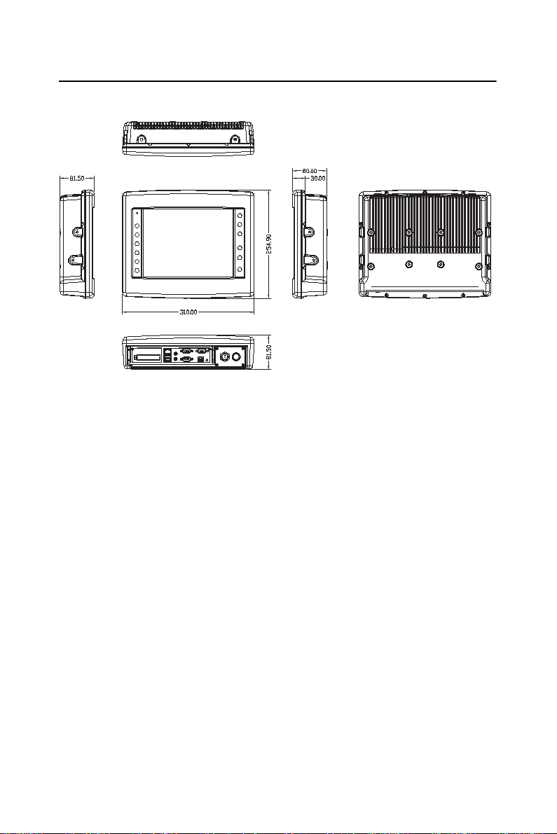
1.7 Dimensions
7 Chapter 1
Page 20

Trek-725 User Manual 8
Page 21

Getting Started
This chapter provides brief instructions
for operating the TREK-725:
• A Quick Tour of TREK-725
• Installation Procedures
CHAPTER
2
Page 22
Chapter 2 Getting Started
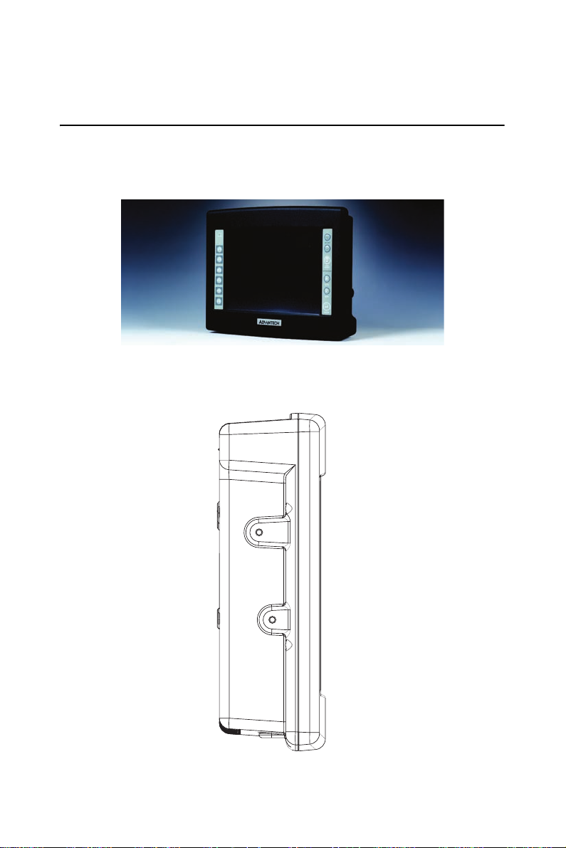
2.1 A Quick Tour of the TREK-725
When you place TREK-725 upright on the desktop, its front panel
appears as shown in Figure 2-1
Figure 2.1: Front View of TREK-725
When you look at the side of TREK-725, you will see the holes for
mounting as shown in Fig. 2-2.
Figure 2.2: Side of TREK-725
Trek-725 User Manual 10
Page 23

When you turn TREK-725 around and look at its rear cover, you will find
VESA standard holes and others for mounting. There are no ventilation
holes, as shown in Figure 2-3.
Figure 2.3: Rear Side View of TREK-725
The I/O placement is at the bottom of TREK-725, as shown in Fig. 2-4.
Figure 2.4: TREK-725 I/O Placement
11 Chapter 2
Page 24

2.2 Installation Procedure
2.2.1 Connecting the Power Cord
We provi de one water-proof DC power inlet cable. You can find it in the
accessory box. If you can not find this cable, please contact your distributor or sales representative.
1. Connect the positive terminal of the power source to the red wire of
the water-proof DC power inlet cable.
2. Connect the ground terminal of the power source to the black wire
of the water-proof DC power inlet cable.
Note: Please ensure the polarity of power is not reversed and the voltage is 24 ~ 48V at 2 A.
3. Plug the water-proof DC power inlet connector in to the DC inlet of
TREK-725.
Note: Please ensure the power switch is OFF before you connect the
water-proof DC power inlet cable.
2.2.2 Switching On the Power
When you look at the bottom of the panel PC, you will see the power
switch. Push it to turn on the unit.
2.2.3 Calibrate the touch screen.
Please refer Chapter 4.4.1.2 to calibrate the touch screen.
Trek-725 User Manual 12
Page 25

3
CHAPTER
Hardware and
Peripheral Installation
This chapter details the installation of
the TREK-725 panel PC hardware.
Sections include:
• Overview of Hardware Installation
and Upgrading
• Main Board
• Charger Board
• RF communication module installation
• System backup battery module
installation
• Installing the 2.5" Hard Disk Drive
• Placing the Rubber Seal
• Placing the Rubber Seal
• Installing the Universal Arm
Page 26
Chapter 3 Hardware and Peripheral
Installation
3.1 Overview of Hardware Installation and Upgrading
The panel PC consists of a PC-based terminal that is housed in a ruggedized aluminum enclosure. Any maintenance or hardware upgrades can
be completed after removing both panels.
Warning! Do not remove the ruggedized aluminum covers
until you have verified that no power is flowing
within the panel PC. Power must be switched off
and the power cord must be unplugged. Every
time you service the panel PC, you should be
aware of this.
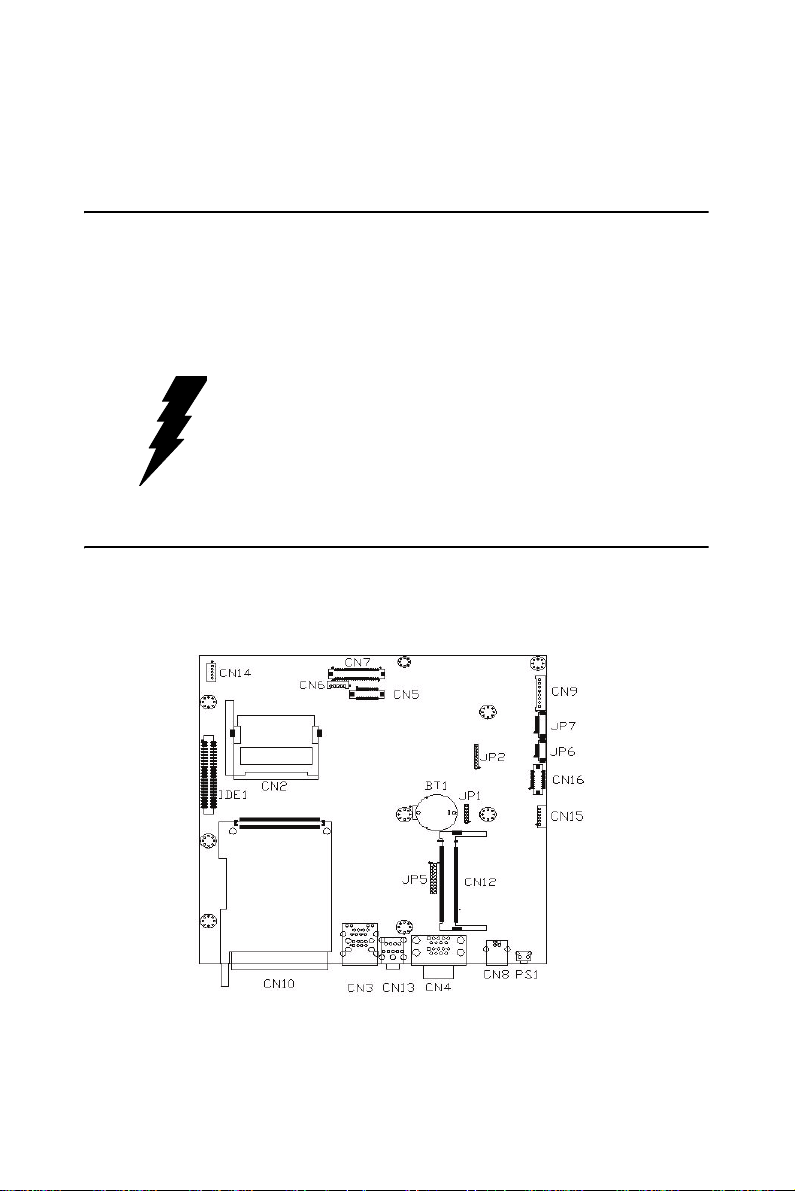
3.2 Main Board
3.2.1 Connector Layout
Figure 3.1: Connector layout of main board
Trek-725 User Manual 14
Page 27

3.2.2 Connector Table
Table 3.1: Connector Table of main board
No. Name Function
1 CN9 POWER in
2 JP7 Function Key
3 JP6 Hot key
4 CN16 GSM/GPRS Adaptor board
Connector
5 CN15 CAN bus Connector
6 PS1 Hardware Reset
7 CN8 USB client
8 CN4 COM1/COM2
9 CN13 Mic in/Line-out
10 CN3 USBx2/LAN
11 CN10 PCMCIA slot
12 IDE1 HDD (reserved)
13 CN2 CF IDE mode (reserved)
14 CN14 Touch Screen
15 CN6 Inverter
16 CN7 LCD (TTL reserved)
17 CN5 LCD LVDS
18 BT1 RTC battery
19 CN12 MiniPCI slot
20 JP5 GPS adaptor (reserved)
21 JP2 CPU JTAG
22 JP1 CPLD JTAG
15 Chapter 3
Page 28
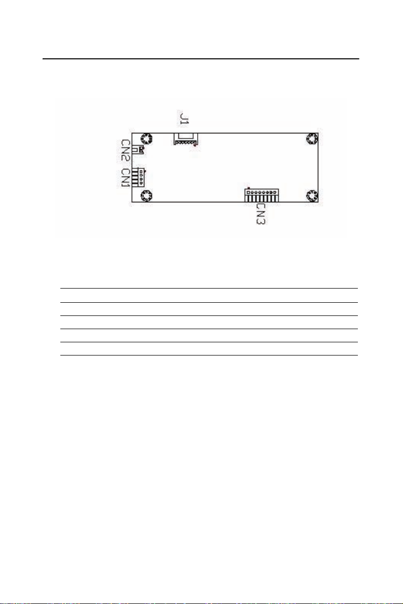
3.3 Charger Board
3.3.1 Connector Layout
Figure 3.2: Connector layout of charger board
3.3.2 Connector Table
Table 3.2: Connector Table of charger board
No. Name Function
1 CN 1 24 ~ 48 V POWER in
2 CN2 Power on switch
3 CN3 19 V Power out
4 J1 Smart Battery Connector
Trek-725 User Manual 16
Page 29

3.4 RF communication module installation
Advantech had already verified some RF communication modules
(MiniPCI WLAN card, GSM/GPRS, and GPS) to increase customer
choice. This section shows how to install these modules.
GSM/GPRS Modular
WiFi Card
(Mini PCI Card)
GPS Modular
Figure 3.3: RF module installation
17 Chapter 3
Page 30
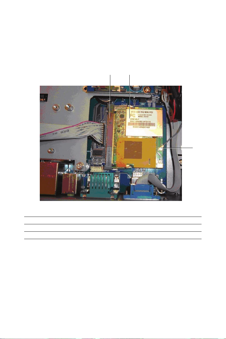
3.4.1 Installation of MiniPCI WLAN Card
Manufacturer name and model name of MiniPCI WLAN Card
1. ZCOM XG601
2. Realtek 8180
1
Figure 3.4: MiniPCI WLAN card installation
1 Mini-PCI connector
2 Wireless LAN card
3 Antenna cable connection point
2
3
Trek-725 User Manual 18
Page 31

3.4.2 Installation of GSM/GPRS module
Manufacturer name and model name of GSM/GPRS module
•SIEMENS MC45
• WaveCom Q2406
1
Figure 3.5: GSM/GPRS antenna installation
1 Antenna cable connection point
19 Chapter 3
Page 32

Figure 3.6: GSM/GPRS module installation
1 GSM/GPRS adaptor board
2 GSM/GPRS module
3 COM port cable
4 SIM connector
1
2
3
4
Trek-725 User Manual 20
Page 33

3.4.3 Installation of GPS module
Manufacturer name and model name of GSM/GPRS module
• Leadtek GPS9546
1
4
Figure 3.7: GPS module installation
1 Antenna cable
2 Adaptor board
3 COM port cable
4 GPS module
2 3
3.5 System backup battery module installation
Advantech reserve one system backup battery module for customer
installation or replacement. This session will show how to install or
replace this module.
Manufacturer name and model name of system backup battery module.
Advantech TREK-725-BP (Smart Li-ion battery, 4S1P 2200mAh)
21 Chapter 3
Page 34

3.5.1 Battery Installation
Manufacturer name and model name of battery module
• Advantech TREK-725-BP
Figure 3.8: Loosen four screws and open the battery panel.
Figure 3.9: Connect the battery.
Trek-725 User Manual 22
Page 35

Figure 3.10: Put the battery into unit.
3.6 Installing the 2.5" Hard Disk Drive (HDD)
You can attach one Enhanced Integrated Device Electronics (EIDE) hard
disk drive to the panel PC's internal controller which uses a PCI local-bus
interface. The advanced IDE controller supports faster data transfer and
allows the IDE hard drive to exceed 528 MB. The following are instructions for installation:
1. Detach the HDD bracket by unscrewing the four screws (#2) on the
top of the HDD bracket.
Screw order number and description.
• 1930030400 M3x4L
• 1933030500 M3x5L
23 Chapter 3
Page 36

2
Screw
1933030500-M3x5L
2
2. Place the HDD inside the HDD bracket and tighten four screws
(#1) from both sides of the HDD bracket.
HDD (Bottom up)
Pin 1
1
Screw
1
1930030400-M3x4L
Trek-725 User Manual 24
Page 37

3. The HDD cable (1 x 44-pin to 1 x 44-pin) is next to the HDD
bracket. Connect the HDD cable to the HDD. Make sure that the
red wire corresponds to Pin 1 on the connector, which is labelled on
the board. Plug the other end of the cable into the HDD, with Pin 1
on the cable corresponding to Pin 1 on the HDD.
3.7 Placing the Rubber Seal
To ensure that your TREK-725 stays dry , the supplied rubber seal must be
placed correctly between the front bezel and back cover. Please note the
direction of the seal. The mark should be up.
Marked
Flat (UP)
UP
Figure 3.11: Placing the Rubber Seal
25 Chapter 3
Page 38

3.8 Installing the Universal Arm
1. Press latches at the same time and then rotate support-1 until you
can see both of the screw holes.
2. Rotate support-2 until th e angle is the sam e as support-1.
3. Use four M4x8L screws and attach the U-Arm with the TREK-725.
The 4 stainless screws can be found in the universal arm's box.
4. Use latches adjust the angle of TREK-725 (every 14.4° on 360°).
Note Support-1 can be on the right or left.
Latch
Support-2
Figure 3.12: Universal Arm
Support-1
Screw-M4x8L
(x4)
TREK-725
Trek-725 User Manual 26
Page 39

4
CHAPTER
Software Functionality
This chapter details the Windows®
Windows® CE 5.0 operating system.
Sections include:
• Introduction
• Windows® CE Startup Procedure
• Upgrade Procedure
• Utilities
•Network
• M-system DOC Flash File System
• Application Program Development
• TREK-725 Windows® CE 5.0
Default Components
Page 40

4.1 Introduction
The TREK-725 is an embedded system using the Windows® CE 5.0 OS.
Windows® CE 5.0 is a compact OS that occupies less storage space and
system resources compared with other operating systems such as Windows® NT or Windo ws® XP. By its modular nature, it is possible to
choose only those functions that are needed for a particular application.
This not only reduces the system resources required, but also reduces
start-up time. In the field of embedded applications, this is an appealing
feature because the impact of downtime is minimized.
Furthermore, the small storage space needed makes OS on solid-state
disk possible, which means higher robustness to harsh environments.
Figure 4.1: Windows® CE 5.0 on the TREK-725
Trek-725 User Manual 28
Page 41

4.2 Windows CE Startup Procedure
Windows CE can be loaded by three methods, through on-board flash,
PCMCIA/CF card, and Ethernet. The presence of an image file (NK.bin)
on a PCMCIA/CF card forces TREK-725 to boot from this PCMCIA/CF
card. Besides booting from PCMCIA/CF card, HyperTerminal can be
used to configure the method of downloading a Windows CE image by
connecting a null modem cable between a PC COM port and the TREK725 COM1 port then following these steps.
4.2.1 Setting up HyperTerminal on PC
1. Execute HyperTerminal
Figure 4.2: Execute HyperTerminal from Start Menu
29 Chapter 4
Page 42

2. Name the HyperTerminal session. Press “OK”
Figure 4.3: Naming HyperTerminal
3. Select the PC COM port used to connect to the TREK-725. Press
“OK”
Trek-725 User Manual 30
Page 43

Figure 4.4: Choose HyperTerminal COM port
4. Setup HyperTerminal by selecting a Baud Rate of 38400 bps, 8
Data Bits, No Parity, one Stop Bi t, and no Flow Control. Press
“OK”.
Figure 4.5: Configure COM port parameters
Now, HyperTerminal is ready to use.
Connect a null modem cable from the PC COM port to the TREK-725
COM1 port.
See section 1.6 for the location of the TREK-725 COM1 port.
4.2.2 Choosing an image download method
1. Power on TREK-725.
31 Chapter 4
Page 44

2. Press “SPACE” to enter the EBOOT Configuration Options window when the HyperTerminal shows the screen below.
Figure 4.6: TREK-725 boot up window
3. Configure EBOOT Configuration Options.
Figure 4.7: TREK-725 Eboot Configuration Options window
Trek-725 User Manual 32
Page 45

Option(0) IP address
Choosing this option allows the configuration of the static IP address that
is used if DHCP is not enabled. This information is configured once and
stored in flash for subsequent downloads. The following prompt is displayed:
Enter new IP address:
You should enter a decimal representation of the IP address with each
byte separated by a decimal point. If you enter no data at the prompt, the
IP address is not changed. If you enter any numbers, they are used. Any
numbers not entered are expanded to zeros. That is, entering 255.255 at
the prompt resolves to 255.255.0.0.
Option (1) Subnet Mask
Choosing this option allows the configuration of the subnet mask that is
used in combination with the static IP address. Just like the IP address,
this information is configured once and stored into flash for subsequent
downloads. The following prompt is displayed:
Enter new subnet mask:
You should enter a decimal representation of the mask with each byte
separated by a decimal point. If you enter no data at the prompt, the mask
is not changed. If you enter any numbers, they are used. Any numbers not
entered are expanded to zeros. That is, entering 255.255 at the prompt
resolves to 255.255.0.0.
Option (2) NPE0 MAC Address
Choosing this option allows the configuration of the static MAC address
that is used for the NPE0 Interface. This information is configured once
and stored into flash for subsequent downloads. The following prompt is
displayed:
Enter new MAC address:
You should enter a hexidecimal representation of the MAC address with
each byte separated by a dash. If you enter no data at the prompt, the
MAC address is not changed. If you enter any numbers, they are used.
Any numbers not entered are expanded to zeros. That is, entering 80-86AA at the prompt resolves to 80-86-AA-00-00-00.
Option (3) NPE1 MAC Address
This option is not used on TREK-725.
Option (4) RNDIS MAC Address
This option is not used on TREK-725.
33 Chapter 4
Page 46

Option (5) Boot Delay
Choosing this option allows the configuration of the number of seconds
that the boot loader waits for user input before continuing with the image
download or launch. The following prompt is displayed:
Enter maximum number of seconds to delay [1-255]:
Option (6) DHCP
Choose this option to enable or disable DHCP. When DHCP is enabled
the static IP address is not used. When DHCP is disabled, the static IP
address is used.
Option (7) Program RAM Image into Flash
Choosing this option instructs the boot loader to store a normal NK.BIN
RAM image into flash memory. This image may be launched via option
(L). When launched, the boot loader reads the entire image out of flash
and stores it into the appropriate location within SDRAM. It then executes this image from SDRAM exactly the same way it would have had it
downloaded the image into RAM and never stored it into flash. Because
the image runs completely out of SDRAM, system performance is
improved due to the faster access speeds associated with this memory
type.
Option (8) Check Image Signature(s)
Choosing this option will check the signature of the downloaded binary
image. Note that the released image is not signed so this is expected to
fail.
Option (A) Automatic Startup Behavior
Choose this option cycles the default boot behavior from downloading a
new image at startup to launching the existing flash resident image. The
existing flash image is the flash image that is programmed when an
NK.BIN image is programmed into flash.
Option (B) Boot Device Order
This option is not used in TREK-725. The boot device is always NPE0.
Option (C) Ethernet Debugging
This option is not used in TREK-725. It must be set to DISABLE.
Option (D) Download Image Now
Choose this option to break out of the menu, save any applicable changes
that were made and then continue with the image download process.
Trek-725 User Manual 34
Page 47

Option (F) Format Flash
Choose this option to format the flash. This will not overwrite EBOOT or
EBOOT parameters.
Option (L) Launch Existing Flash Resident Image Now
Choose this option to exit the menu, save any applicable changes that
were made and then launch the previously programmed flashed image.
Option (M) Display Mode Setup
Mode (0) (800x600), Mode (1) (640x480),
Mode (2) (1024x768), Mode (3) (320x24)
Choose this option to configure the display resolution. The default
TREK-725 configuration is Mode (0).
Option (R) Reset to Factory Default Configuration
Choose this option to reset user-configurable settings to the following
factory defaults.
IP address 192.168.80.2
Subnet mask 255.255.0.0
NPE0 MAC Address 80-86-22-22-22-22
NPE1 MAC Address 80-86-33-33-33-33
RNDIS MAC Address 80-86-44-44-44-44
Boot delay 5 seconds
DHCP Enabled
Program RAM image into
FLASH
Check image signature(s) Disabled
Automatic Startup Behavior Download new image via Ethernet
Boot device order PCI NIC RT8139D -> NPE0 -> NPE1
Ethernet debugging Enabled
Disabled
Note: When you reset the user-configurable settings, you must ch ange
option (C) Ethernet debugging setting from Enable to Disable for bootup Windows CE successfully.
35 Chapter 4
Page 48

4.2.3 EBOOT configuration examples
Ex1: Launch on-board flash image
Do not enter the EBOOT Configuration menu, or in the EBOOT Configuration menu choose option (L) to launch the on-board flash image.
Ex2: Download a Windows CE image over Ethernet without programming an image into Flash.
1. Set option (7) to DISABLE.
2. Choose option (D) to start downloading the image.
Ex3: Download Windows CE image from Ethernet and program this
image into Flash.
1. Set option (7) to ENABLE.
2. Choose option (D) to start downloading the image.
4.3 Upgrade Procedure
After the OS image has been built, we may want to burn it to the on-board
flash ROM. Advantech provides the upgrade utility
“UpgradeIXP_1.01.07.exe” to upgrade Bootloader image, WinCE image,
or boot logo in the on-boar d flash ROM. The upgrade procedure is as follows:
1. Copy the “UpgradeIXP_1.01.07.exe” utility and image files (for
example: NK.NB0, EBOOT.NB0, and WINDOWSCE.BMP) to a
CF storage card.
Note: NK.NB0 is a WinCE image, EBOOT.NB0 is a Bootloader image,
and WINDOWSCE.BMP is a boot bitmap.
Trek-725 User Manual 36
Page 49

2. Insert the CF storage card in to the TREK-725, then launch
UpgradeIXP_1.01.07.exe.
Figure 4.8: Image files and upgrade utility in CF storage card
3. Check the items you want to upgrade as shown in Figure 4.8. If you
want to upgrade the boot logo, you can input the path of the bitmap
file in the edit box or click the ‘Browse’ button to select the file.
Note: The option “NK.NB0 (Normal, XIP)” means that the nk.nb0 will
be written directly to the flash ROM, and “NK.NB0 (Compressed)”
means that nk.nb0 is compressed first, then written to the flash ROM.
• Boot time: compressed image takes longer to boot.
• Flash file system size: compressed OS image results in a larger
flash file system size.
37 Chapter 4
Page 50

4. Press the ‘Apply’ button. The items you selected will be written to
the flash ROM. See Figure 4.9.
Figure 4.9: Press Apply button to upgrade on-board flash ROM
Reboot the system after the upgrade process is done.
4.4 Utilities
There are several useful utilities added to the standard Windows® CE 5.0
OS.
4.4.1 System Configurator
System Configurator is an outstanding utility designed by Advantech
Windows® CE software team. It is an integrated environment where the
user can get useful system information as well as configure favorite system settings and system control functions on demand. Double click the
System Configurator icon on the desktop. The following sections illustrate the functions of System Configurator.
Trek-725 User Manual 38
Page 51

4.4.2 General
Memory information including DRAM and FLASH file system information is displayed on the General page. This page also shows the versions
of each part of the installed embedded OS, including Windows® CE 5.0,
Bootloader, and System Configurator.
Figure 4.10: General information
39 Chapter 4
Page 52

4.4.3 Calibration
The Touch-screen page provides the calibration function. Click the “calibration” button. The “Stylus Properties” windows appears. Click the “calibrate” button in the Stylus Properties window to start the calibration
process. During the calibration process, the user taps on the center of the
target on the screen, then the target moves to the next position. After calibration, a dialog appears to ask the user if they want to save the registry.
Figure 4.11: Touch-screen calibration
Trek-725 User Manual 40
Page 53

Figure 4.12: Save Registry or not after calibration
41 Chapter 4
Page 54

4.4.4 Display
Sometimes it is unnecessary to have the display attached to the TREK725 fully powered all day . The Disp lay page provides two freq uently used
functions—display resolution and brightness adjustment.
Figure 4.13: Display configuration
NOTE: Users can set the idle time to turn off the backlight automatically from the backlight page in the Display Properties applet of the
Control Panel. When the backlight is off, the mouse, keyboard, or
touchscreen can turn it on again.
Trek-725 User Manual 42
Page 55

Figure 4.14: Display Properties dialog
4.4.5 Watchdog timer
It is important in industrial applications that control systems rarely crash,
or are capable of self-recovery if they are halted somehow. The watchdog
function is provided to reset the TREK-725 if the software crashes. There
is a countdown timer inside the watchdog function. The user’s application
program enables the watchdog timer, then regularly reloads this countdown timer. If the user’s application program crashes, it fails to reload the
countdown timer and when the countdown timer reaches zero, the TREK725 is reset. The watchdog function in the TREK-725 provides eight different time intervals: 2 seconds, 5 seconds, 10 seconds, 30 seconds, 60
seconds, 2 minutes, 5 minutes, and 10 minutes. The “Test” button is used
to start the watchdog countdown function, and the “Enable Trigger” button is used to trigger the watchdog periodically.
43 Chapter 4
Page 56

Figure 4.15: Watchdog timer
4.4.6 Miscellaneous
The Misc page provides several functions as described below. The “Registry” block provides registry save, clear, and view functions. The “MAC
ID” block shows the network MAC address. The “COMM” block provides IPConfig and ActiveSync communication functions. The “Reset”
Block provides “Cold Boot” and “Start Upgrade” functions. “Cold Boot”
is used to reboot the system. “Start Upgrade” is used to automatically
download an image over the Ethernet interface and program this image
into flash after a system reboot.
Trek-725 User Manual 44
Page 57

Figure 4.16: Miscellaneous settings
4.4.7 Startup execution
The TREK-725 has a useful function called “Startup execution”. After
the system boots up, the startup execution function automatically begins.
This function is useful for control systems to initialize processes or other
procedures. In TREK-725, there is one way to configure the “Startup”
function.
Method
1. Create a “startup” directory on a CF storage card or in a folder
called “\Mounted Volume\”.
2. Copy executable files to the “startup” directory that was created in
step 1.
Example
We copy the executable files “tty.exe” to “\DiskOnChip\Startup”, and
then reboot the system. After the system boots up, “tty.exe” is automatically executed.
45 Chapter 4
Page 58

4.4.8 Hotkey Configuration
The TREK-725 provides a utility named HotkeyControl.exe for the user
to configure the hotkeys.
Figure 4.17: Hotkeys Control
4.5 Network
4.5.1 Networking via Ethernet
TREK-725 has one built-in 100Base-T Ethernet controller. It appears in
“Control Panel/Network and Dial-up Connections” as
“IXP425ETHNPE1”. The user can configure Ethernet support as follows:
1. Click “Start/Settings/Control Panel” .
2. Double click “Network and Dial-up Connections”.
3. This window displays all available connections. Click the connection icon to see its pop-up menu. Users can disable, rename, or
modify properties from this pop-up menu.
4. If the TREK-725 is a node on a LAN with DHCP servers, it is now
available for use on the LAN.
Trek-725 User Manual 46
Page 59

5. If the TREK-725 is a node on a LAN with fixed IP addressing, the
user has to ask MIS for a subnet mask and specific IP address. The
user then enters them into the associated fields of the Properties
Dialog that is opened by selecting the properties item on the pop-up
menu described in step 3 above. Use “System Configurator\Misc\Registry\Save” on the desktop to save this changed registry. Reboot the system. The Ethernet functions are available as in
the previous configuration.
Figure 4.18: Networking via Ethernet
4.5.2 Networking via PPP
The TREK-725 supports the PPP protocol. To set up and use the PPP protocol, follow the steps below.
1. Click “Start/Settings/Network and Dial-up Connections”.
2. Make a new connection. When the dialog box appears, choose
“Dial-Up Connection”. Click “Next”.
3. Click “Configure” to set up the device according to the specification of your modem, and then click “OK” (in the top-right corner of
the window).
4. Click “Next”. Type the telephone number in the “Phone Number”
window. Press “Finish” to complete the setup process.
47 Chapter 4
Page 60

5. Turn on your modem and use an RS-232 cable to connect the
modem to the COM1 port of the TREK-725.
6. Double click the connection you made in Step 4. Type in the user
name, password and domain for the dial-up connection and click
“Connect”.
Figure 4.19: Networking via PPP
4.5.3 Web browser
The TREK-725 built-in Windows CE OS includes the IE browser. It can
be used to browse web pages on World Wide Web via LAN or PPP connections.
4.6 M-system DOC Flash File System
4.6.1 Introduction to M-system DOC Flash File System
The M-system DOC Flash File System was designed and developed specifically as an enhancement to Microsoft Windows CE operating systems
to eliminate extra disk-like storage such as storage cards, redundant RAM
and ROM.
Trek-725 User Manual 48
Page 61

4.6.2 DiskOnChip folder in TREK-725
TREK-725 uses M-system DOC Flash to use the free space of flash
ROMs for persistent storage. The M-system DOC Flash file system
region of the system is located in the “\DiskOnChip” directory. Any file
or directory stored in the “\DiskOnChip” directory is kept persistently,
even if the TREK-725 is turned off. The user can store software or data in
“\DiskOnChip” rather than on CF cards to avoid inconvenience.
4.7 Application Program Development
The TREK-725 is bundled with the Windows® CE 5.0 operating system.
In real applications, the user needs to execute various application programs on the operating system. However, unlike other Windows operating systems (98, 2000, XP, and XPE), Windows® CE 5.0 is a hardwaredependent operating system. That is to say, users must rebuild application
programs by using TREK-725's software development kit (SDK).
4.7.1 System requirements
• Intel® Pentium 90 MHz CPU or more advanced
• Microsoft® Windows® 2000 Professional or Windows® XP
• Microsoft® eMbedded Visual Tools 4.0
• Platform SDK for TREK-725
• 64 MB DRAM
• CD-ROM drive
• Monitor with VGA resolution at least
• Mouse
• 200 MB free hard disk space at least
• TREK-725 platform
• The host PC and TREK-725 need to be connected on the same LAN to
do kernel debugging if necessary
49 Chapter 4
Page 62

4.7.2 Building programs for Windows CE
The platform SDK is bundled as standard with the TREK-725. Users can
build the Windows CE runtime application program with the SDK and
eMbedded Visual Tools.
Figure 4.20: Flowchart of building the Windows® CE 5.0 runtime
4.7.3 How to install the SDK
Copy the “IXP_BSP_BETA2_SDK.msi” TREK-725 SDK file to your
PC, and launch it. You can install SDK by following these steps.
1. Launch the TREK-725 SDK file, and then click the “Next” button.
Figure 4.21: Install TREK-725 SDK
Trek-725 User Manual 50
Page 63

2. Accept the license agreement and click “Next”.
Figure 4.22:
3. Type in your information and click “Next”.
Figure 4.23:
51 Chapter 4
Page 64

4. Choose the setup type: “Embed ded Visual C++”, “Microsoft .NET
Compact Framework”, or “Documentation” in Custom Setup.
Figure 4.24:
Figure 4.25:
Trek-725 User Manual 52
Page 65

5. Click the “Install” button to install the SDK.
Figure 4.26:
The SDK begins to install.
Figure 4.27:
53 Chapter 4
Page 66

6. Click “Finish” to comple te the instal lation process.
Figure 4.28:
4.7.4 Running your application programs
ActiveSync automatically transfers the built application program to the
TREK-725 platform. Choose IXP_BSP_BETA2 as the SDK type after
compiling your application program.
Figure 4.29:
Trek-725 User Manual 54
Page 67

4.8 TREK-725 Windows® CE 5.0 Default Components
4.8.1 Applications and Services Development
Figure 4.30:
Figure 4.31:
55 Chapter 4
Page 68

4.8.2 Applications – End User
Figure 4.32:
4.8.3 Core OS Services
Figure 4.33:
Trek-725 User Manual 56
Page 69

Figure 4.34:
4.8.4 Communication Services and Networking
Figure 4.35:
57 Chapter 4
Page 70

Figure 4.36:
Figure 4.37:
Trek-725 User Manual 58
Page 71

Figure 4.38:
4.8.5 Device Management
Figure 4.39:
59 Chapter 4
Page 72

4.8.6 File Systems and Data Store
Figure 4.40:
Figure 4.41:
Trek-725 User Manual 60
Page 73

4.8.7 Fonts
Figure 4.42:
Figure 4.43:
61 Chapter 4
Page 74

4.8.8 International
Figure 4.44:
4.8.9 Internet Client Services
Figure 4.45:
Trek-725 User Manual 62
Page 75

Figure 4.46:
4.8.10 Graphics and Multimedia Technologies
Figure 4.47:
63 Chapter 4
Page 76

Figure 4.48:
Figure 4.49:
Trek-725 User Manual 64
Page 77

4.8.11 Security
Figure 4.50:
4.8.12 Shell and User Interface
Figure 4.51:
65 Chapter 4
Page 78

Figure 4.52:
4.8.13 Windows CE Error Reporting
Figure 4.53:
Trek-725 User Manual 66
Page 79

4.8.14 Voice Over IP Phone Services
Figure 4.54:
4.9 Advantech API Library
Advantech Library for eVC
Installation Guide 03/03/2005
Copyright (C) 2005 Advantech Co., Ltd.
Latest update: 03/17/2005
4.9.1 Update History
Date Description
20050317 Add AdvlibRegFlushKey()
Remove AdvLibBrightApply() Dialog
4.9.2 Release notes
This software package release is version 1.0.1. These Advantech API
calls can support only the TREK-725.
67 Chapter 4
Page 80

4.9.3 File layout
ReadMe.txt
ADVLib.h Header file
ADVLib.lib Library file
AdvLib.dll Dynamic linked library release version
TestAPI.zip An API demo project
4.9.4 Application development with this Library
All API functions are exported from the Advlib.DLL dynamic link
library. A header file Advlib.h and library Advlib.LIB for C/C++ are provided in the Include and Library directories. There are six classes of API
functions.
Watchdog API
BOOL AdvLibWDSetConfig(DWORD delay, int timeout);
BOOL AdvLibWDTrigger(void);
BOOL AdvLibWDDisable(void);
Get MAC Address API
BOOL AdvLibGetMacAddr(char* tmpStr);
Adjust Brightness
BOOL AdvLibBrightGet(BYTE *brightness);
BOOL AdvLibBrightSet(BYTE brightness);
BOOL AdvLibBrightApply(void);
Set Display Resolution
BOOL AdvLibSetResolution(int DisplayModeIndex);
On/Off Backlight
BOOL AdvLibScreenOn(void);
BOOL AdvLibScreenOff(void);
Registry Flush
BOOL AdvLibRegFlushKey(void);
Trek-725 User Manual 68
Page 81

4.9.5 Watchdog API
If you are developing an eVC project, you can call these functions to control the watchdog timer. The normal procedure is call AdvLibWDSetConfig() to set the time interval, then the watchdog timer will be enabled.
After setting and enabling the watchdog timer, you must trigger (ping) the
watchdog timer within the time interval you set, or the system will reboot.
Finally, you could call AdvLibWDDisable() to stop the watchdog function.
AdvLibWDSetConfig
This API call sets the configuration of the watchdog driver.
* BOOL AdvLibWDSetConfig(DWORD delay, int timeout)
+ Parameters
- delay
[in] An initial delay in milliseconds before first timeout period.
- timeout
[in] Watchdog timeout in seconds. The range is set from 0 to 60.
+ Return Value
- TRUE (nonzero) on success.
FALSE (zero) on failure.
+ Remarks
This function enables and activates the watchdog timer with the given
parameters. After the watchdog timer is activated, the application should
regularly call AdvLibWDTrigger() within the specified timeout in milliseconds.
NOTE: If you set Parameter timeout to 0, the watchdog will reboot system immediately.
69 Chapter 4
Page 82

AdvLibWDTrigger
Tell the watchdog timer that the application is still working.
* BOOL AdvLibWDTrigger(void)
+ Parameters
- No parameters
+ Return Value
- TRUE (nonzero) on success.
FALSE (zero) on failure.
+ Remarks
After the watchdog timer is activated, the application should call this
function regularly to indicate that it is still working properly. If the watchdog timer is activated, and the application doesn’t call AdvLibWDTrigger() after timeout seconds, the system will reboot.
AdvLibWDDisable
This function disables the watchdog timer.
* BOOL AdvLibWDDisable(void);
+ Parameters
- No parameters
+ Return Value
- TRUE (nonzero) on success.
FALSE (zero) on failure.
+ Remarks
If the watchdog timer is not longer required, the application can call Adv-
LibWDDisable() to disable the watchdog timer. The return value may be
FALSE if the watchdog hardware can not be stopped.
Trek-725 User Manual 70
Page 83

4.9.6 Get MAC Address API
If you want to know the MAC address of the on-board network card you
can call AdvLibGetMacAddr() to get it.
AdvLibGetMacAddr
Call this function to get the on-board network card MAC address.
* BOOL AdvLibGetMacAddr(char* tmpStr)
+ Parameters
- tmpStr
[out] On-board network card MAC id.
+ Return Value
- TRUE (nonzero) on success.
FALSE (zero) on failure.
+ Remarks
None.
4.9.7 Adjust Brightness
There are three functions to control LCD panel brightness. If you want to
get the current LCD panel brightness value, you can call AdvLibBrightGet(). It will return a value form 0 to 255. If you want to set the LCD
panel brightness, you should call AdvLibBrightSet() to set the brightness
you want, then write the brightness to flash ROM with AdvLibBrightApply(), or your brightness setting is volatile.
AdvLibBrightGet
Call this function to get the current screen brightness.
* BOOL AdvLibBrightGet(BYTE *brightness)
+ Parameters
- brightness
[out] The current screen brightness. The range is set from 0 to 255.
+ Return Value
- TRUE (nonzero) on success.
FALSE (zero) on failure.
+ Remarks
The brightness range is the set of contiguous integer values that applica-
tions can control. The range is set from 0 to 255. The brightness 0 is darkest, and the brightness 255 is brightest.
71 Chapter 4
Page 84

AdvLibBrightSet
Call this function to set the screen brightness.
* BOOL AdvLibBrightSet(BYTE brightness);
+ Parameters
- brightness
[in] Specifies the new screen brightness. The range is set from 0 to 255.
+ Return Value
- TRUE (nonzero) on success.
- FALSE (zero) on failure.
+ Remarks
The brightness range is the set of contiguous integer values that applica-
tions can control. The range is set from 0 to 255. The brightness 0 is darkest, and the brightness 255 is brightest.
AdvLibBrightApply
Call this function to write the screen brightness to flash.
* BOOL AdvLibBrightApply(void)
+ Parameters
- No parameters
+ Return Value
- TRUE (nonzero) on success.
FALSE (zero) on failure.
+ Remarks
This function writes the screen brightness to flash. If you don't call this
function, your brightness setting is volatile.
Trek-725 User Manual 72
Page 85

4.9.8 Set Display Resolution
Set the display resolution with AdvLibSetResolution(). You need to
restart your TREK-725 before new settings take effect.
AdvLibSetResolution
Set display resolution
* BOOL AdvLibSetResolution(int DisplayModeIndex)
+ Parameters
- DisplayModeIndex
[in] Display resolution index. The range is set from 0 to 2. Index 0, 1,
and 2 correspond to 640x480, 800x600, and 1024x768 resolutions.
+ Return Value
- TRUE (nonzero) on success.
FALSE (zero) on failure.
+ Remarks
You could use pre-defined statements to replace DisplayModeIndex. The
following statements are written in Advlib.h.
#define SET_RESOLUTION_800X6000
#define SET_RESOLUTION_640X4801
#define SET_RESOLUTION_1024X7682
4.9.9 On/Off Backlight
You can call AdvLibScreenOn() to turn on the LCD panel backlight, and
turn off it with AdvLibScreenOff().
AdvLibScreenOn
Call this function to turn on the LCD panel backlight.
* BOOL AdvLibScreenOn(void)
+ Parameters
- No parameters
+ Return Value
- TRUE (nonzero) on success.
FALSE (zero) on failure.
+ Remarks
Turns on the LCD panel backlight.
73 Chapter 4
Page 86

AdvLibScreenOff
Call this function to turn off the LCD panel backlight.
* BOOL AdvLibScreenOff(void)
+ Parameters
- No parameters
+ Return Value
- TRUE (nonzero) on success.
FALSE (zero) on failure.
+ Remarks
Turns off the LCD panel.
4.9.10 Registry flush
Writes all the attributes of the specified open registry key into the flash
ROM.
AdvLibRegFlushKey
Call this function to flush the registry.
* BOOL AdvLibRegFlushKey(void)
+ Parameters
- No parameters
+ Return Value
- TRUE (nonzero) on success.
FALSE (zero) on failure.
+ Remarks
If you want your previous registry changes to be committed by flushing
data to flash ROM, you can call AdvLibRegFlushKey. Calling AdvLibRegFlushKey frequently may degrade performance.
4.9.11 Build a Platform with this library
If you want to build this driver into your Windows CE OS image, just add
the following lines to your Platform.bib. Don't forget to put AdvLib.dll
into your Platform's $(_FLATRELEASEDIR).
MODULES
AdvLib.dll$(_FLATRELEASEDIR)AdvLib.dllNK SH
Finally, make the image.
Trek-725 User Manual 74
Page 87

Programming the
Watchdog Timer
The TREK-725 is equipped with a
watchdog timer that resets the CPU or
generates an interrupt if processing
comes to a standstill for any reason.
This feature ensures system reliability
in industrial standalone or unmanned
environments.
Appendix
A
Page 88

Appendix A Programming the Watchdog Timer
A.1 Programming the Watchdog Timer
To program the watchdog timer, you must write a program which writes I/
O port address 440 (hex). The output data is a time interval value. The
value range is from 01 (hex) to 3F (hex), and the related time interval is
from 1 sec. to 63 sec.
Data Time Interval
01 1 sec.
02 2 sec.
03 3 sec.
04 4 sec.
ïï
ïï
ïï
3F 63 sec.
After data entry, your program must refresh the watchdog timer b y rewrit-
ing the I/O port 440 (hex) while simultaneously setting it. When you want
to disable the watchdog timer, your program should read I/O port 440
(hex).
The following example shows how you might program the watchdog
timer:
;----------------------------------------------------------------------------------; Enter the extended function mode, interruptible double-write |
;----------------------------------------------------------------------------------MOV DX,2EH
MOV AL,87H
OUT DX,AL
OUT DX,AL
Trek-725 User Manual 76
Page 89

;----------------------------------------------------------------------------; Configure logical device 8, configuration register CRF6 |
;----------------------------------------------------------------------------MOV DX,2EH
MOV AL,07H ; point to Logical Device Number Reg.
OUT DX,AL
MOV DX,2FH
MOV AL,08H ; select logical device 8
OUT DX,AL
;
MOV DX,2EH
MOV AL,30H ;Set watch dog activate or inactivate
OUT DX,AL
MOV DX,2FH
MOV AL,01H ; 01:activate 00:inactivate
OUT DX,AL
;
MOV DX,2EH
MOV AL,F5H ; Setting counter unit is second
OUT DX,AL
MOV DX,2FH
MOV AL,00H
OUT DX,AL
;
MOV DX,2EH
MOV AL,F6H
OUT DX,AL
MOV DX,2FH
MOV AL,05H ; Set 5 seconds
OUT DX,AL
77 Appendix A
Page 90

;-----------------------------------------; Exit extended function mode |
;-----------------------------------------MOV DX,2EH
MOV AL,AAH
Trek-725 User Manual 78
Page 91

Appendix
Pin Assignments
This appendix contains information on
TREK-725’s pin assignments.
B
Page 92

Appendix B Pin Assignments
B.1 CPLD JTAG (JP1)
This is a JP6F-2mm-D90 connector.
Pin Signal
1CPLD_TCK
2CPLD_TDI
3CPLD_TDO
4CPLD_TMS
5 SYS_VCC3.3
6GND
B.2 CPU JTAG (JP2)
Pin Signal
1SA_TCK
2SA_TDI
3SA_TDO
4SA_TMS
5 nJTAG TRST
6GND
Trek-725 User Manual 80
Page 93

B.3 GPS Adaptor (JP5)
This is a 10 x 2 pin-header connector.
Pin Signal Pin Signal
1 ANT_Power 2 5 V
3 GPS_BAT 4 3.3 V
5 nGPS_RST 6 No Connection
7 No Connection 8 No Connection
9 UART4_RXD 10 GND
1 1 UART4_RXD 12 UART4_TXD
13 UART5_TXD 14 UART5_RXD
15 UART5_TXD 16 GND
17 No Connection 18 GND
19 No Connection 20 No Connection
B.4 Inverter Power Connector (CN6)
Pin Signal
1+12V
2GND
3 ENVBK
4VBR
5GND
81 Appendix B
Page 94

B.5 IDE Hard Disk Drive Connector (IDE1)
Pin Signal Pin Signal
1IDE RESET #2GND
3DATA 74DATA 8
5DATA 66DATA 9
7DATA 58DATA 10
9 DATA 4 10 DATA 11
11 DATA 3 12 DATA 12
13 DATA 2 14 DATA 13
15 DATA 1 16 DATA 14
17 DATA 0 18 DATA 15
19 SIGNAL GND 20 N/C
21 HDD DREQ 22 GND
23 IO WRITE 24 GND
25 IO READ 26 GND
27 HD READY 28 CABLE SELECT
29 HDACK 0 # 30 GND
31 IRQ14 32 N/C
33 ADDR 1 34 N/C
35 ADDR 0 36 ADDR 2
37 HDD SELECT 0 # 38 HDD SELECT 1 #
39 IDE ACTIVE 0 # 40 GND
41 Vcc 42 VCC
43 GND 44 N/C
# low active
Trek-725 User Manual 82
Page 95

B.6 LVDS Connector (CN5)
Pin Signal Pin Signal
1 VCC3P3 2 VCC3P3
3GND 4GND
5 LVDS_N0 6 LVDS_P0
7 GND 8 LVDS_N1
9 LVDS_P1 10 GND
11 LVDS_N2 12 LVDS_P2
13 GND 14 LVDS_N3
15 LVDS_P3 16 GND
17 LVDS_CLKN 18 LVDS_CLKP
19 GND 20 GND
83 Appendix B
Page 96

B.7 Flat Panel Display Connector (CN7) (Reserved)
Pin Signal Pin Signal
1 VDD 2 VDD
3GND 4GND
5 VDD 6 VDD
7Vcon 8GND
9B0 10B1
11 B2 12 B3
13 B4 14 B5
15 B6 16 B7
17 G0 18 G1
19 G2 20 G3
21 G4 22 G5
23 G6 24 G7
25 R0 26 R1
27 R2 28 R3
29 R4 30 R5
31 R6 32 R7
33 GND 34 GND
35 SHCLK 36 FLM
37 M/DE 38 LP
39 Reserved 40 ENAVEE
B.8 USB Client (CN8 & JP13)
This is a 4-pin 2 mm wafer connector.
Pin Signal
1GND
2 SA_BUSB_DPR
3 SA_BUSB_DNR
4 USB_LINK_5V
Trek-725 User Manual 84
Page 97

B.9 Touchscreen (CN14)
This is a 5-pin 2 mm wafer connector.
Pin Signal
1Y+_UR
2 Y-_LR
3TS_IN3
4X+_UL
5X-_LL
B.10 CAN Bus Connector (CN15)
Pin Signal
1VCC
2NC
3AGND
4CAN_H
5CAN_L
6AGND
85 Appendix B
Page 98

B.11 GSM/GPRS Adaptor Board Connector (CN16)
This is a DF13-20DP-1.25C connector.
Pin Signal Pin Signal
1 UART3_CTS 2 nGSM_RST
3 UART3_RTS 4 GND
5 UART3_TXD 6 GND
7 UART3_RXD 8 GND
9 UART3_DCD 10 UART6_CTS
11 UART3_DSR 12 UART6_RTS
13 UART3_DTR 14 GSM_VCC
15 UART3_RI 16 GSM_VCC
17 UART6_TXD 18 GSM_VCC
19 UART6_RXD 20 GSM_VCC
B.12 COM1 & COM2
Pin Signal
1DCD
2RxD
3TxD
4DTR
5GND
6DSR
7RTS
8CTS
9RI
Trek-725 User Manual 86
Page 99

B.13 USB Port
Pin Signal
1 VCC
2 DATA3 DATA+
4 GND
87 Appendix B
Page 100

Trek-725 User Manual 88
 Loading...