

Traynor Acoustic Master Custom YS, Acoustic Master Custom Service Manual
U.S.A.
Yorkville Sound Inc.
4625 Witmer Industrial Estate
Niagara Falls, New York
14305 USA
Voice: (716) 297-2920
Fax: (716) 297-3689
WORLD HEADQUARTERS
WEB ACCESS: http://www.yorkville.com
CANADA
Yorkville Sound
550 Granite Court
Pickering, Ontario
L1W-3Y8 CANADA
Voice: (905) 837-8481
Fax: (905) 837-8746
Quality and Innovation Since 1963
Printed in Canada
SERVICE MANUAL
Acoustic Master
Custom
MODEL TYPE: YS1084
IMPORTANT SAFETY INSTRUCTIONS
This lightning flash with arrowhead symbol, within
an equilateral triangle, is intended to alert the user to
the presence of uninsulated “dangerous voltage”
within the product’s enclosure that may be of sufficient
magnitude to constitute a risk of electric shock to persons.
Ce symbole d’éclair avec tête de flèche dans un triangle
équilatéral est prévu pour alerter l’utilisateur de la présence d’un
« voltage dangereux » non-isolé à proximité de l’enceinte du
produit qui pourrait être d’ampleur suffisante pour présenter
un risque de choque électrique.
FOLLOW ALL INSTRUCTIONS SUIVEZ TOUTES LES INSTRUCTIONS
Instructions pertaining to a risk of fire,
electric shock, or injury to a person
CAUTION: TO REDUCE THE RISK OF ELECTRIC
SHOCK, DO NOT REMOVE COVER (OR BACK).
NO USER SERVICEABLE PARTS INSIDE.
REFER SERVICING TO QUALIFIED SERVICE PERSONNEL.
THIS DEVICE IS FOR INDOOR USE ONLY!
Read Instructions: The Owner’s Manual should be read and understood before operation
of your unit. Please, save these instructions for future reference and heed all warnings.
Clean only with dry cloth.
Packaging: Keep the box and packaging materials, in case the unit needs to be
returned for service.
Warning: To reduce the risk or fire or electric shock, do not expose this apparatus to rain or
moisture. Do not use this apparatus near water!
Warning: When using electric products, basic precautions should always be followed,
including the following:
Power Sources
Your unit should be connected to a power source only of the voltage specified in the
owners manual or as marked on the unit. This unit has a polarized plug. Do not use
with an extension cord or receptacle unless the plug can be fully inserted. Precau-
tions should be taken so that the grounding scheme on the unit is not defeated. An
apparatus with CLASS I construction shall be connected to a Mains socket outlet with
a protective earthing ground. Where the MAINS plug or an appliance coupler is used
as the disconnect device, the disconnect device shall remain readily operable.
Hazards
Do not place this product on an unstable cart, stand, tripod, bracket or table. The
product may fall, causing serious personal injury and serious damage to the product.
Use only with cart, stand, tripod, bracket, or table recommended by the manufacturer
or sold with the product. Follow the manufacturer’s instructions when installing the
product and use mounting accessories recommended by the manufacturer. Only use
attachments/accessories specified by the manufacturer
Note: Prolonged use of headphones at a high volume may cause
health damage on your ears.
The apparatus should not be exposed to dripping or splashing water; no objects
filled with liquids should be placed on the apparatus.
Terminals marked with the “lightning bolt” are hazardous live; the external wiring
connected to these terminals require installation by an instructed person or the use of
ready made leads or cords.
Ensure that proper ventilation is provided around the appliance. Do not install near
any heat sources such as radiators, heat registers, stoves, or other apparatus
(including amplifiers) that produce heat.
No naked flame sources, such as lighted candles, should be placed on the apparatus.
Power Cord
Do not defeat the safety purpose of the polarized or grounding-type plug. A polarized plug
has two blades with one wider than the other. A grounding type plug has two blades and a
third grounding prong. The wide blade or the third prong are provided for your safety. If the
provided plug does not fit into your outlet, consult an electrician for replacement of the
obsolete outlet. The AC supply cord should be routed so that it is unlikely that it will be
damaged. Protect the power cord from being walked on or pinched particularly at plugs. If
the AC supply cord is damaged DO NOT OPERATE THE UNIT. To completely disconnect
this apparatus from the AC Mains, disconnect the power supply cord plug from the AC
receptacle. The mains plug of the power supply cord shall remain readily operable.
Unplug this apparatus during lightning storms or when unused for long periods of time.
Service
The unit should be serviced only by qualified service personnel. Servicing is required
when the apparatus has been damaged in any way, such as power-supply cord or plug is
damaged, liquid has been spilled or objects have fallen into the apparatus, the apparatus
has been exposed to rain or moisture, does not operate normally, or has been dropped.
The exclamation point within an equilatereal triangle is
intended to alert the user to the presence of important
operating and maintenance (servicing) instructions in
the literature accompanying the appliance.
Le point d’exclamation à l’intérieur d’un triangle équilatéral
est prévu pour alerter l’utilisateur de la présence
d’instructions importantes dans la littérature accompag-
nant l’appareil en ce qui concerne l’opération et la
maintenance de cet appareil.
S2125A
Instructions relatives au risque de feu,
choc électrique, ou blessures aux personnes
AVIS: AFIN DE REDUIRE LES RISQUE DE CHOC ELECTRIQUE,
N’ENLEVEZ PAS LE COUVERT (OU LE PANNEAU ARRIERE)
NE CONTIENT AUCUNE PIECE REPARABLE PAR L’UTILISATEUR.
CONSULTEZ UN TECHNICIEN QUALIFIE POUR L’ENTRETIENT
CE PRODUIT EST POUR L’USAGE À L’INTÉREUR SEULEMENT
Veuillez Lire le Manuel: Il contient des informations qui devraient êtres comprises avant
l’opération de votre appareil. Conservez. Gardez S.V.P. ces instructions pour consultations
ultérieures et observez tous les avertissements.
Nettoyez seulement avec le tissu sec.
Emballage: Conservez la boite au cas ou l’appareil devait être retourner pour réparation.
Avertissement: Pour réduire le risque de feu ou la décharge électrique, n'exposez pas
cet appareil à la pluie ou à l'humidité. N’utilisez pas cet appareil près de l’eau!
Attention: Lors de l’utilisation de produits électrique, assurez-vous d’adhérer à des
précautions de bases incluant celle qui suivent:
Alimentation
L’appareil ne doit être branché qu’à une source d’alimentation correspondant au
voltage spécifié dans le manuel ou tel qu’indiqué sur l’appareil. Cet appareil est équipé
d’une prise d’alimentation polarisée. Ne pas utiliser cet appareil avec un cordon de
raccordement à moins qu’il soit possible d’insérer complètement les trois lames. Des
précautions doivent êtres prises afin d’eviter que le système de mise à la terre de
l’appareil ne soit désengagé. Un appareil construit selon les normes de CLASS I
devrait être raccordé à une prise murale d’alimentation avec connexion intacte de mise
à la masse. Lorsqu’une prise de branchement ou un coupleur d'appareils est utilisée
comme dispositif de débranchement, ce dispositif de débranchement devra demeurer
pleinement fonctionnel avec raccordement à la masse.
Risque
Ne pas placer cet appareil sur un chariot, un support, un trépied ou une table instables.
L’appareil pourrait tomber et blesser quelqu’un ou subir des dommages importants.
Utiliser seulement un chariot, un support, un trépied ou une table recommandés par le
fabricant ou vendus avec le produit. Suivre les instructions du fabricant pour installer
l’appareil et utiliser les accessoires recommandés par le fabricant. Utilisez seulement
les attachements/accessoires indiqués par le fabricant
Note: L'utilisation prolongée des écouteurs à un volume élevé peut
avoir des conséquences néfastes sur la santé sur vos oreilles. .
Il convient de ne pas placer sur l’appareil de sources de flammes nues, telles que
des bougies allumées.
L’appeil ne doit pas être exposé à des égouttements d’eau ou des éclaboussures
et qu’aucun objet rempli de liquide tel que des vases ne doit être placé sur l’appareil.
Assurez que lappareil est fourni de la propre ventilation. Ne procédez pas à
l’installation près de source de chaleur tels que radiateurs, registre de chaleur, fours
ou autres appareils (incluant les amplificateurs) qui produisent de la chaleur.
Les dispositifs marqués d’une symbole “d’éclair” sont des parties dangereuses
au toucher et que les câblages extérieurs connectés à ces dispositifs de
connection extérieure doivent être effectivés par un opérateur formé ou en utilisant
des cordons déjà préparés.
Cordon d’Alimentation
Ne pas enlever le dispositif de sécurité sur la prise polarisée ou la prise avec tige de
mise à la masse du cordon d’alimentation. Une prise polarisée dispose de deux lames
dont une plus large que l’autre. Une prise avec tige de mise à la masse dispose de
deux lames en plus d’une troisième tige qui connecte à la masse. La lame plus large ou
la tige de mise à la masse est prévu pour votre sécurité. La prise murale est désuète si
elle n’est pas conçue pour accepter ce type de prise avec dispositif de sécurité. Dans
ce cas, contactez un électricien pour faire remplacer la prise murale. Évitez
d’endommager le cordon d’alimentation. Protégez le cordon d’alimentation. Assurezvous qu’on ne marche pas dessus et qu’on ne le pince pas en particulier aux prises.
N’UTILISEZ PAS L’APPAREIL si le cordon d’alimentation est endommagé. Pour
débrancher complètement cet appareil de l’alimentation CA principale, déconnectez le
cordon d’alimentation de la prise d’alimentation murale. Le cordon d’alimentation du
bloc d’alimentation de l’appareil doit demeurer pleinement fonctionnel.
Débranchez cet appareil durant les orages ou si inutilisé pendant de longues périodes.
Service
Consultez un technicien qualifié pour l’entretien de votre appareil. L'entretien est
nécessaire quand l'appareil a été endommagé de quelque façon que se soit. Par exemple
si le cordon d’alimentation ou la prise du cordon sont endommagés, si il y a eu du liquide
qui a été renversé à l’intérieur ou des objets sont tombés dans l'appareil, si l'appareil a été
exposé à la pluie ou à l'humidité, si il ne fonctionne pas normalement, ou a été échappé.
safety-4v8 • April 14/2011

Specifications
Model:
Type:
Cabinet Program Power (Watts):
Cabinet Impedance (ohms):
Power @ min. impedance (Watts):
Minimum Impedance (ohms):
Burst Power - 2 cycle:
Speaker Configuration - LF (Size / Power):
Speaker Configuration - HF (Size / Power):
Frequency Response (Hz +/-3dB):
Hum and Noise (dB):
Input Channels:
Channel 1 - inputs:
Channel 1 - controls:
Channel 2 - inputs:
Channel 2 - controls:
Channel 2 - switches:
Channel 3 - inputs:
Channel 3 - controls:
Channel 4 - inputs:
Channel 4 - controls:
Channel 5 - inputs:
Master Volume Control:
Main Tone Controls:
Graphic EQ:
Input Sensitivity (mV):
Master Outputs:
Line Out (type / configuration):
Line Out Sensitivity (Vrms):
Effects Volume:
Effects Loop / Location:
Effects Footswitch / Function:
Effects Return Sensitivity (Vrms):
Internal Reverb / Effects:
LED Indicators:
Protection:
External speaker output / location:
Headphone Jack:
Dimensions (DWH, inches):
Dimensions (DWH, cm):
Weight (lbs / kg):
Acoustic Master Custom
Acoustic Combo Amplifier
225
4
225
4
250
150 watt, 2-inch voice coil, 8-inch woofer
2 X 1-inch Neo Dome Tweeter
50- 20 kHz
-98
4 + Aux
1
gain, 4 band tone control, Notch, D-EFX (ch1/2)
1
gain, 4 band tone control, Notch
EFX enable/disable
1
gain, 4 band tone control, Notch, D-EFX
1
gain, monitor channel post Master Volume
RCA pre master volume
yes
no, independent
no
ch1/100, ch2/100, ch3/100, ch4/100
no
1/4-inch jack post EFX / XLR Pre EFX
1
wet and dry control
inserts on ch1-3
ch1/2 and ch3
0.5
DSP
Power, clip
EFX input limiter, Clip limiter
no
no
12.5 x 20 x 13
50.8 x 32 x 33
35 / 15.9
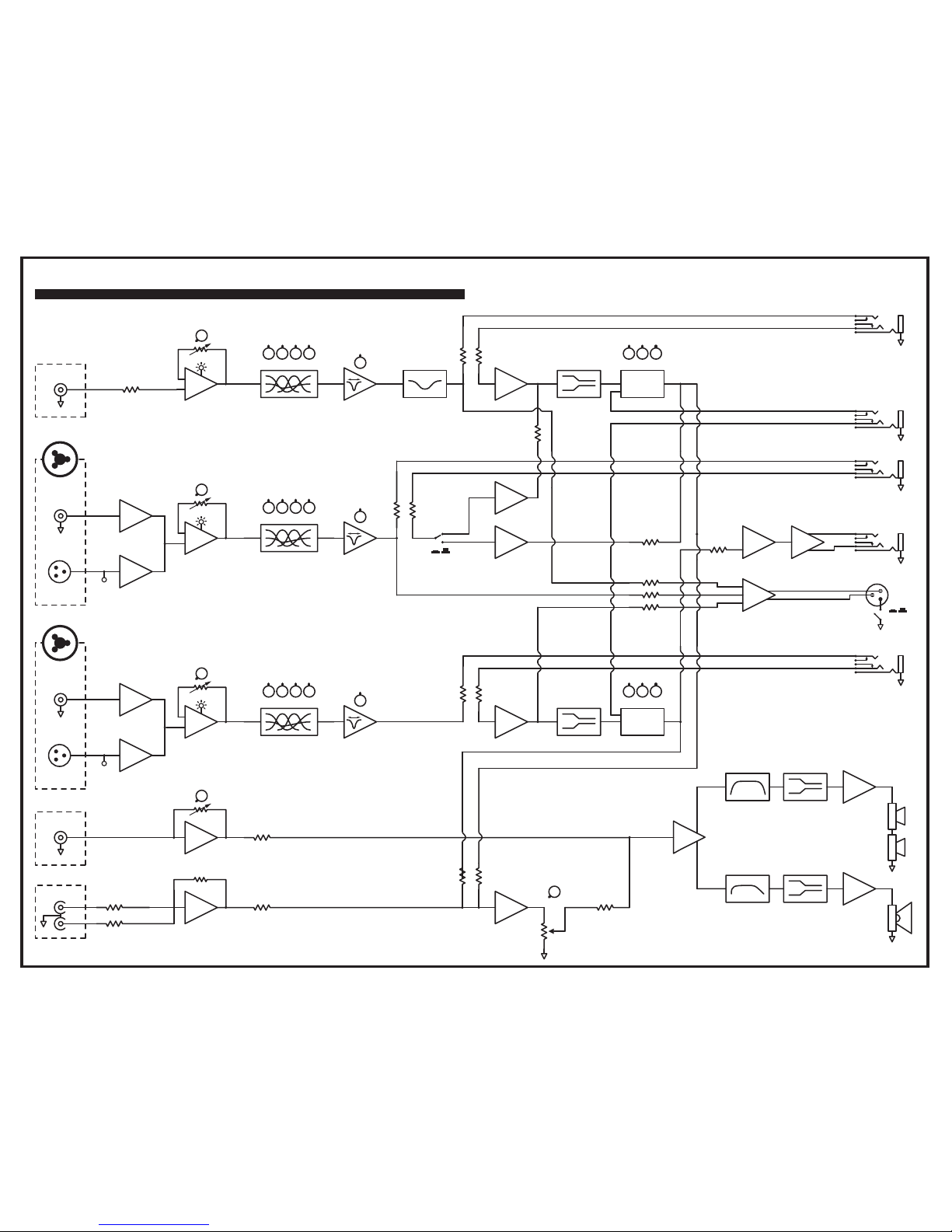
Block Diagram for Acoustic Master Custom
DESIGNED AND MANUFACTURED BY YORKVILLE SOUND
BLOCK-DIAG-AM-CUSTOM-00-1v0
XLR
1/4-inch
Balanced
Fixed
Equalization
Limiter
Limiter
Limiter
BP Filter
BP Filter
HF Amp
LF Amp
Limiter
Digital Effects
DSP 1
DSP 2
Select/Mod/Mix
1/4-inch
High Z
Gain 1
1/4-inch
Channel 1
Channel 2
Channel 3
Aux Input (Ch 4)
Master
Volume
RCA Input
Tone Controls
Insert Jack
Channel 1
Feedback
Notch Filter
Bass/Lo-Mid/Hi-Mid/Treble
Tone Controls
Bass/Lo-Mid/Hi-Mid/Treble
Feedback
Notch Filter
XLR
1/4-inch
Balanced
Tone Controls
Bass/Lo-Mid/Hi-Mid/Treble
Feedback
Notch Filter
∑
∑
∑
∑
RCA
Post DSP
Line Out
Digital Effects
Select/Mod/Mix
Insert Jack
Channel 3
Insert Jack
Channel 2
Footswitch
Ch 2 Effects
Bypass
Input 1
Gain Pot
In 1
CLIP
Input 2
Gain Pot
In 2
CLIP
Phantom
Power
15V
Fixed
Gain
Fixed
Gain
1/4-inch / XLR
Combi-Jack
1/4-inch / XLR
Combi-Jack
Input 3
Gain Pot
In 2
CLIP
Aux Input (Ch 4)
Gain Pot
Phantom
Power
48V
Fixed
Gain
Fixed
Gain
XLR Line Out
Pre-Effects
GND Lift
Ch 1/2 DSP Enable
Ch 3 DSP Enable

11 11
10 10
9 9
8 8
7 7
6 6
5 5
4 4
3 3
2 2
1 1
A
A
B
B
C
C
D
D
E
E
F
F
G
G
H
H
I
I
J
J
K
K
L
L
M
M
N
N
O
O
P
P
Q
Q
of
Filename:
PCB# Sheet 31
Product
Date: Rev: YsType:YsType
M1408V02sch.sch2006
M1408
Thu Jul 12, 2012
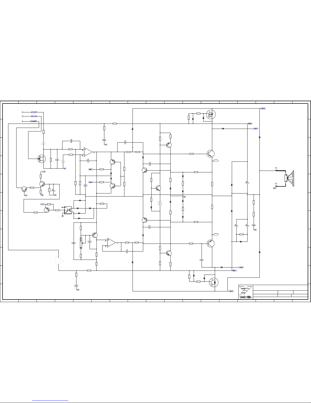
HF-amp
V02
AM-CUSTOM
+
1/4W
33K
R97
.
1/4W
7K5
R38
.
1/4W
4K99
R18
.
+
12
12 W1:L
10
12 W1:J
8
12 W1:H
6
12 W1:F
4
12 W1:D
2
12 W1:B
R37
1/4W
.
7K5
C12
63V 470N
C40
63V 1U
R78
1/4W
.
49K9
R115
1/4W
.
10K0
C27
63V1U
1/4W
4K99
R13
.
11
12 W1:K
7
12 W1:G
5
12 W1:E
9
12 W1:I
3
12 W1:C
1
12 W1:A
63V
C50
100N
U6:A
MC33079P
C5
16V33U
63V
C4
100N
R36
1/4W
.
4K99
C11
100V15N
R14
1/4W
.
10K0
63V
C49
100N
U6:B
MC33079P
+
1/4W
1K
R73
.
R46
1/4W
.
100R
U6:C
MC33079P
1/4W
4K99
R34
.
1/4W
.
R70
1K
1/4W
.
R58
1K
U5:B
LM13600N
Q3
5104
TO92
MPSA56
1/4W
33K
R30
.
R35
1/4W
.
49K9
100V
C38
33N
Q23
5101
BC550C
TO92
Q22
5102
BC560C
TO92
1/4W
10K0
R129
.
1/4W
1K
R133
.
R33
1/4W
.
10K0
4148
D18
U8:B
MC33079P
+
1/4W
33K
R114
.
4148
D8
R49
1/4W
.
2K
1/4W
1K0
R15
MINI
C20
63V10U
1/4W
.
33K
R116
25V
C21
100U
400V
C18
1N
R96
1/4W
.
49K9
1/4W
33K
R94
.
1/4W
.
33K
R117
63V
C28
1U
1/2W
10R
R43
.
63V
C29
220N
C22
100V47P
1/4W
.
10K0
R98
W2
TWEETER
WHT
63V
C6
100N
4
V+
11
V-
U8:E
4
V+
11
V-
U6:E
1/4W
10K0
R8
.
U11:E
63V
C56
100N
R32
1/4W
.
100R
U5:A
LM13600N
1/4W
100R
R131
.
1/4W
20K0
R132
MINI
R47
1/4W
.
10K0
1/4W
10K0
R20
.
63V
C13
10U
1N5237B
ZD13
0W5
8V2
R40
1/4W
MINI
20K0
U11:A
LM13600N
C10
100V15N
C8
100V15N
R11
1/4W
.
4K99
1N5245B 15V0
ZD90W5
4007
D19
R92
1/4W
.
100R
R93
1/4W
.
100R
63V
C7
100N
+
C17
100V15N
U1:A
MC33078P
R19
1/4W
.
10K0
R17
1/4W
.
4K99
U1:B
MC33078P
R16
1/4W
.
10K0
R130
1/4W
.
2K
R79
1/4W
.
7K5
U8:A
MC33079P
R71
1/4W
.
7K5
1/4W
.
R57
1K
C35
63V470N
(VCC)
LM13600N
Dual VCA
6745
U5:C
1/4W
100K
R39
.
1/4W
20K0
R50
MINI
1/2W
10R
R42
.
R21
1/4W
.
2K
100V
C19
680P
2
NC1
6
NC2
11
NC3
LM3886
U7
R41
1/4W
MINI
20K0
U8:C
MC33079P
U8:D
MC33079P
R126
1/4W
.
100R
SP3
HORN
#7497
U5:E
63V
C9
100N
63V
C42
100N
8
V+
4
V-
U1:C
1/4W
4K99
R12
.
1/4W
4K99
R48
.
1/4W
33K
R31
.
1/4W
10K0
R72
.
250V
C39
4N7
C34
16V
10U
(VCC)
LM13600N
Dual VCA
6745
U11:C
R127
1/4W
.
100R
U11:B
LM13600N
1/4W
.
10K0
R95
#7497
SP1
HORN
LF-Amp[B1]
(VCC)
LM13600N
Dual VCA
6745
U5:D
U6:D
MC33079P
LF-Amp[B2]
RIBBON CABLE CONNECTOR
TO M1409 PRE-AMP BOARD.
(VCC)
LM13600N
Dual VCA
6745
U11:D
11 11
10 10
9 9
8 8
7 7
6 6
5 5
4 4
3 3
2 2
1 1
A
A
B
B
C
C
D
D
E
E
F
F
G
G
H
H
I
I
J
J
K
K
L
L
M
M
N
N
O
O
P
P
Q
Q
of
Filename:
PCB# Sheet 32
Product
Date: Rev: YsType:YsType
M1408V02sch.sch2006
M1408
Thu Jul 12, 2012
LF-Amp
V02
AM-CUSTOM
1/4W
2K87
R88
.
1/4W
6K8
R85
.
2.0W
2R
R82
.
2.0W
2R
R81
.
4148
D39
4148
D41
R87
1/4W
.
150R
TP2
TP1
+
TO92
Q24
5101
BC550C
1/4W
10K0
R135
.
C58
16V
33U
100V
C61
220P
1/4W
45K3
R125
.
50V
C60
10N
M
Lin
4520
10K
RT1
BIAS
63V
C48
1U
1/4W
10K0
R68
.
4148
D42
ZD60W5
1N5225B 3V0
1/8W
681R
R86
FLMP
1/4W
17K8
R89
.
R123
1/4W
.
4K12
4148
D40
R101
1/4W
.
100K
1/4W
11R
R124
FUSIBLE
50V
C59
10N
C37
50V470P
R76
1/4W
.
100R
1/4W
2K7
R119
.
R66
1/4W
.
200R
C36
50V470P
C53
100V47N
Q17
5104
MPSA56
TO92
1/4W
33K
R62
.
4148
D29
1/4W
270K
R61
.
C52
100V47N
4148
D35
1/8W
22R1
R103
FLMP
1/4W
324R0
R104
0.1%
1/4W
3K16
R63
.
4148
D47
NTC
10K
R56
6619
1/4W
4K12
R118
.
1/8W
22R1
R99
FLMP
1/4W
324R0
R100
0.1%
R69
1/4W
FUSIBLE
33R
1N5254B
ZD44
0W5
27V0
4148
D43
R84
1/4W
.
150R
1N5254B
ZD37
0W5
27V0
R64
1/4W
FUSIBLE
33R
BAV21
D26
2.0W
2K2
R59
.
2SB1647
6812
Q13:A
TO3P
5.0W
0R15
R77
.
5.0W
0R15
R75
.
6805
Q11:A
2SD2560
TO3P
ZD2
16V0
1N4745A
1W0
G
S
D
IRL2910
Q8
TO220
4148
D34
25V
C45
100U
1N4745A
ZD5
1W0
16V0
D32
1N5402
100V
C51
22N
25V
C46
330U
25V
C44
330U
1N5402
D27
W4
BLK
SPRK-GND
R106
1/4W
.
1K3
1/4W
20K0
R137
MINI
C62
16V
33U
R121
1/4W
.
10K0
8
V+
4
V-
U10:C
R107
1/4W
MINI
1K0
50V
C63
22U
4148
D38
1/4W
4K12
R91
.
1/4W
11R
R113
FUSIBLE
100V
C47
220P
1/4W
120R
R112
MINI
TO92
Q12
5106
MPSA63
R102
1/4W
.
100K
1/4W
270R
R120
MINI
4148
D36
Q15
5103
MPSA06
TO92
1/4W
4K12
R105
.
BC550C
Q16
5101
TO92
4148
D45
Q14
5102
BC560C
TO92
BAV21
D31
2.0W
2K2
R74
.
1/4W
6K8
R108
.
4148
D46
1N4745A
ZD3
1W0
16V0
1N4745A
ZD4
1W0
16V0
W5
WOOFER
RED
BAV21
D25
R90
1/4W
MINI
47R
50V
C32
100N
WITH AMP COLD
ADJUST BIAS TO 2mV
BETWEEN TP1 AND TP2
4148
D48
R122
1/4W
.
10K0
TO92
Q21
5122
J109
C54
100V100P
R111
1/4W
.
14K0
U10:B
MC33078P
R109
1.0W
.
3K9
C55
100V10P
1/4W
1K0
R128
MINI
BAV21
D30
R67
1/4W
.
100R
U10:A
MC33078P
Q18
5102
BC560C
TO92
R65
1/4W
.
100R
R60
1/8W
FLMP
100R0
MR854
D33
MR854
D28
R55
1/8W
FLMP
100R0
Q20
MPSA56
5104
TO92
6
5
4
4N35
6880
U9:B
2
1
4N35
6880
U9:A
1/4W
10K0
R139
.
Q26
5102
TO92
BC560C
Q19
5101
BC550C
TO92
R110
1/4W
MINI
47R
Q10
5101
BC550C
TO92
R83
1/4W
.
10K0
100V
C33
220P
S
G
D
Q9
IRF4905
TO220
P
HF-amp[P4]
SP2
WOOFER
#7510
HF-amp[P2]
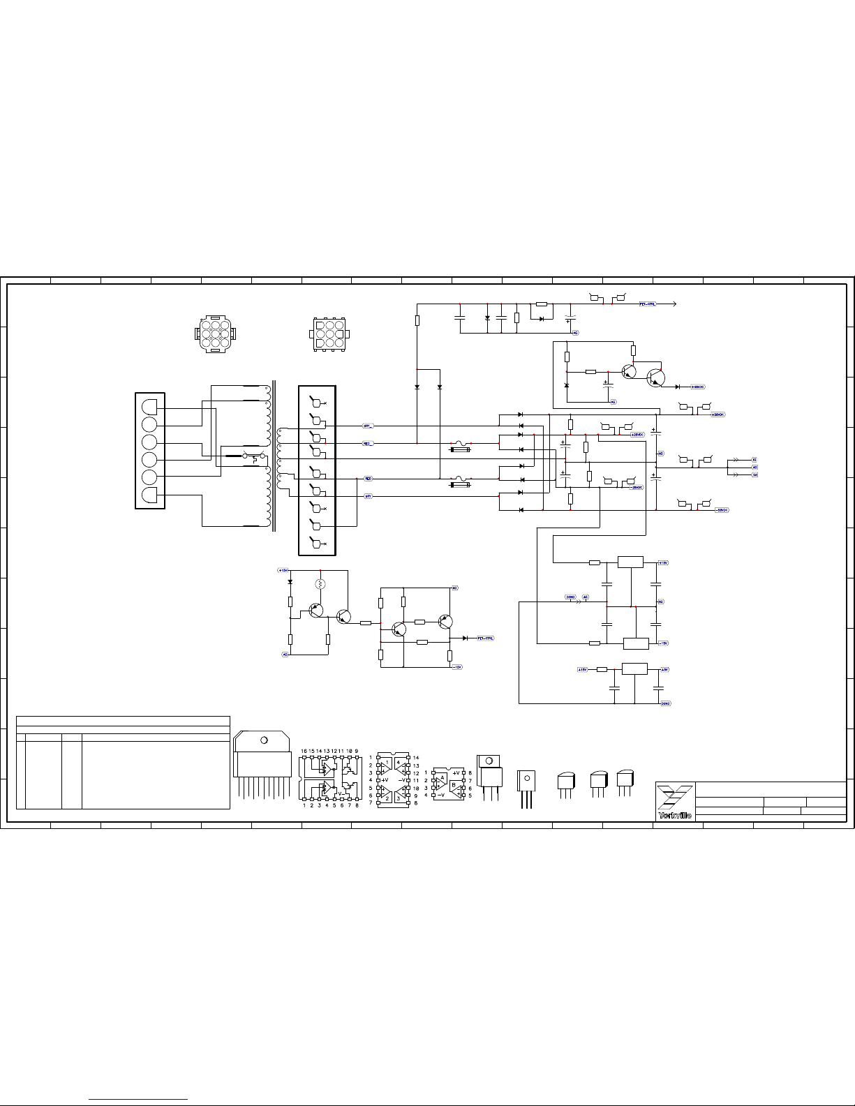
Power supply[N1]
11 11
10 10
9 9
8 8
7 7
6 6
5 5
4 4
3 3
2 2
1 1
A
A
B
B
C
C
D
D
E
E
F
F
G
G
H
H
I
I
J
J
K
K
L
L
M
M
N
N
O
O
P
P
Q
Q
of
Filename:
PCB# Sheet 33
Product
Date: Rev: YsType:YsType
M1408V02sch.sch2006
M1408
Thu Jul 12, 2012
Power supply
V02
AM-CUSTOM
3
YEL
RED_
1
NC
RED
GRY
6 9
NC
4 7
YEL
3
RED_
6
NC1NC
4
RED
9
NC
GRY_
7
2
5
8
1/4W
47K
R24
.
2
5
8
1/4W
1K3
R7
.
1/4W
78K7
R6
.
1/4W
14K0
R1
.
TRANSFORMER PRIMARY
FEMALE CONNECTOR
1/4W
470K
R23
.
5
4
3
RED
NC
GRY_
RED
GRY
2.5 AMP
F1
D22 6A2
D23 6A2
D15 6A2
D21 6A2
D20
6A2
D17
6A2
6
6W7:F
1
6 W6:A
4
6 W6:D
3
6 W6:C
6
2
1
Q5
5113
TO92
MPSA42
1/4W
10K0
R10
.
Q2
5113
MPSA42
TO92
4007
D24
1/4W
4K7
R2
.
1/4W
22K
R4
.
Q1
5104
TO92
MPSA56
F2
2.5 AMP
4007
D10
63V
C1
1U
D14 6A2
D16 6A2
63V
C2
1U
4148
D1
SC3
R27
1.0W
FLMP
1R
1/2W
15K
R22
.
50V
C41
4700U
1/2W
15K
R80
.
1/2W
15K
R54
.
50V
C30
4700U
1/2W
15K
R53
.
R44
1/4W
.
49K9
1/4W
33K
R52
.
1N5262B
ZD1
0W5
51V0
63V
C3
2U2
IN
REF
OUT
NJM7805FA
6855U4TO220
63V
C25
1U
IN
REF
OUT
NJM7815FA
6856U2TO220
80V
C43
4700U
2
6 W6:B
80V
C31
4700U
TO92
Q6
5103
MPSA06
1/4W
10R
R51
.
5
6 W6:E
4148
D11
GRY
RED
YEL
RED_
GRY_
CH1410U
XF2:C
1/4W
2K49
R25
.
R45
10K
6619
NTC
4148
D4
R28
1.0W
FLMP
1R
63V
C24
1U
IN
REF
OUT
NJM7915FA
TO220
6857 U3
BD139
BD237
BD238
MJE340
MJE350
MJE271
MJE270
BD140
ECB
BC
TO-92
MPSA63
MPSA43
2N5551
E
MPSA56
MPSA06
MPSA13
2N5401
SG
TO-92
2N5638
D
J109
WHITE
BLUE
ORANGE
R5
1/4W
.
1M
NC
6
W3:F 9
NC
PCB SECONDARY
MALE CONNECTOR
R29
1.0W
FLMP
1R
4
6W7:D
SC2
3
6W7:C
SC1
1
6W7:A
6
6 W6:F
BROWN
BLACK
YEL/BLK
TRANSFORMER SECONDARY
FEMALE CONNECTOR .
6840_PC
R26
1/4W
.
82K5
R9
1/4W
.
100K
Q4
5102
BC560C
TO92
NC
9
W3:I 9
5
W3:E 9
4
W3:D 9
3
W3:C 9
7
W3:G 9
2
W3:B 9
ZD21
0W5
27V0
1N5254B
50V
C15
33P
2
6W7:B
5
6W7:E
TO126
Q7
BD139
6774
50V
C23
22U
4007
D3
R3
1/4W
.
1M
LF-Amp[B1]
BLU
BLK
ORN
CH1410U
XF2:A
WHT
BLK/YEL
BRN
CH1410U
XF2:B
8
W3:H 9
1
W3:A 9
50V
C14
33P
50V
C16
33P
63V
C26
1U
6745_PC
6804_PC
DS
MTP10N15
MTP12P10
IRL2910
MTP2P50E
IRF830
IRF4905
IRF720
G
TO-220
MTP8P20
IRF5210
MTP23P06
IRF822
BE
TO-92
BC560C
C
BC550C
AG = AMP GROUND
IG = INPUT GROUND
SG = SIGNAL GROUND
1 4376109
V+
V-
OUTPUT
NC
GND
V_IN+
V_IN-
11852
LM3886T
NC
MUTE
NC(+)
NC
13
10
7
4
1
9
11
12
8
#
2
3
5
6
VER#
MODEL(S):-
DATE DESCRIPTION OF CHANGE
V
V
V
V
V1.00
V
V
V
V
V
V
V
D
D
D
D
FEB-2010
N
N
N
N
RELEASED FOR PRODUCTION
AM-CUSTOM
D
D
D
D
D
D
D
N
N
N
N
N
N
M1408
12-JUL-2012 V02 PC8448: #3392 improved pad GG
Change #6467 with #6619 10K NTC GG
 Loading...