

Traynor Acoustic Master AM150, YS1007 Owner's Manual
O W N E R ’ S M A N U A L
A
C
O
U
S
T
I
C
M
A
S
T
E
R
G U I D E D E L ’ U T I L I S A T E U R
Traynor Acoustic Master
A M 1 5 0
MODEL TYPE: YS1007

IMPORTANT SAFETY INSTRUCTIONS
safety-4v2.eps Aug 26/05
CAUTION:
TO REDUCE THE RISK OF ELECTRIC SHOCK, DO
NOT REMOVE COVER (OR BACK).
NO USER SERVICEABLE PARTS INSIDE.
REFER SERVICING TO QUALIFIED
SERVICE PERSONNEL.
INSTRUCTIONS PERTAINING TO A
RISK OF FIRE, ELECTRIC SHOCK,
OR INJURY TO PERSONS
Read Instructions
The Owner’s Manualshould be read and understood
before operation of your unit. Please, save these instructions for future reference.
Packaging
Keep the box and packaging materials, in case the unit
needs to be returned for service.
Warning
When using electric products, basic precautions should
always be followed, including the following:
Power Sources
Your unit should be connected to a power source only of the voltage
specified in the owners manual or as marked on the unit. This unit has
a polarized plug. Do not use with an extension cord or receptacle
unless the plug can be fully inserted. Precautions should be taken so
that the grounding scheme on the unit is not defeated.
Hazards
Do not place this product on an unstable cart, stand, tripod, bracket or
table. The product may fall, causing serious personal injury and serious
damage to the product. Use only with cart, stand, tripod, bracket, or
table recommended by the manufacturer or sold with the product.
Follow the manufacturer’s instructions when installing the product and
use mounting accessories recommended by the manufacturer.
The apparatus should not be exposed to dr
ipping or splashing water;
no objects filled with liquids should be placed on the apparatus.
Te
rminals marked with the “lightning bolt” are hazardous live; the
external wiring connected to these terminals require installation by an
instructed person or the use of ready made leads or cords.
No naked flame sources, such as lighted candles, should be
placed on the apparatus
.
Power Cord
The AC supply cord should be routed so that it is unlikely that it will be
damaged. If the AC supply cord is damaged DO NOT OPERATE THE UNIT.
Service
The unit should be serviced only by qualified service personnel.
AVIS:
AFIN DE REDUIRE LES RISQUE DE CHOC ELECTRIQUE,
N’ENLEVEZ PAS LE COUVERT (OU LE P
ANNEAU ARRIERE)
NE CONTIENT AUCUNE PIECE
REPARABLE PAR L’UTILISATEUR.
CONSULTEZ UN TECHNICIEN QUALIFIE
POUR L’ENTRETIENT
INSTRUCTIONS RELATIVES AU RISQUE
DE FEU, CHOC ÉLECTRIQUE, OU
BLESSURES AUX PERSONNES
Veuillez Lire le Manuel
Il contient des informations qui devraient êtres comprises
avant
l’opération de votre appareil. Conservez S.V.P. ces
instructions pour consultations ul
térieures.
Emballage
Conservez la boite au cas ou l’appareil devait être
retourner pour
réparation.
Attention:
Lors de l’utilisation de produits électrique, assurez-vous
d’adhérer à des précautions de bases incluant celle qui
suivent:
Alimentation
L’appareil ne doit être branché qu’à une source d’alimentation
correspondant au voltage sp
écifié dans le manuel ou tel qu’indiqué sur
l’appareil. Cet appareil est équipé d’une prise d’alimentation polarisée.
Ne pas utiliser cet appareil avec un cordon de raccordement
à moins
qu’il soit possible d’insérer complètement les trois lames. Des
précautions doivent êtres prises afin d’eviter que le système de mise à
la terre de
l’appareil ne soit désengagé.
Risque
Ne pas placer cet appareil sur un chariot, un support, un trépied ou une
table instables.
L’appareil pourrait tomber et blesser quelqu’un ou subir
des dommages importants. Utiliser seulement un chariot, un support,
un tr
épied ou une table recommandés par le fabricant ou vendus avec
le produit. Suivre les instructions du fabricant pour installer l’appareil et
utiliser les accessoires recommand
és par le fabricant.
Il convient de ne pas placer sur
l’appareil de sources de flammes
nues, telles que des bougies allumées.
L’appeil ne doit pas être exposé à des égouttements d’eau ou des
éclaboussures et qu’aucun objet rempli de liquide tel que des vases
ne doit
être placé sur l’appareil.
Les dispositifs marqu
és d’une symbole “d’éclair” sont des parties
dangereuses au toucher et que les
câblages extérieurs connectés à
ces dispositifs de connection ex
térieure doivent être effectivés par un
opérateur formé ou en utilisant des cordons déjà préparés.
Cordon d’Alimentation
Évitez d’endommager le cordon d’alimentation. N’UTILISEZ PAS
L’APPAREIL si le cordon d’alimentation est endommagé.
Service
Consultez un technicien qualifié pour l’entretien de votre appareil.
A
C
O
U
S
T
I
C
M
A
S
T
E
R
DESIGN ED AND MANUFACT URED B Y
YORKVILLE SOUND • Toronto, CANADA
BAL
BAL
TYPE: YS1007 z530-1v3
230V
50Hz 1.0A
120VAC
60Hz 2.0A
FUSE: T 1,0A
FUSE: T 2.0A SloBlo
CAUTION: REPLACE FUSE
WITH SAME TYPE AND RATING
AT
TENTION: UTILISER UN FUSIBLE
DE RECHANGE DE MEME
TYPE ET CALIBRE
CH. 2
EFX SEND
CH. 2
EFX RT
N
LEFT / MONO
LINE OUT
RIGH
T
LINE OUT
LINE OUT
(pre-EFX)
(post-EFX)
EFX
FOO
TSW.
1. Rvb/Del ay/Chor
2. Reverb On
e
3. Flange & Dela
y
4. Chorus & Pitc
h
5. Reverb & Flange
6. Reverb Tw
o
7. Rvb & Choru s
8. Detune d Chorus
9. Dela y & Choru s
10. Pitch Shif
t
11. Slap Delay
12. Chorus
13. Reverb & D ela
y
14. Doubl
e
15. Flange
16. Delay?
0 10
1 9
2 8
3 7
4 6
5
GAIN
2
1
INPUT INPUT
NOTCH
DIGITAL EFFECTS
15 15
12 12
9 9
6 6
3 3
MID
15 15
12 12
9 9
6 6
3 3
HIGH
15 15
12 12
9 9
6 6
3 3
LOW
0 10
1 9
2 8
3 7
4 6
5
MASTER
VO
LUME
ACTIVE
EFFECTS
DEFEAT
80
12
0 625
80
0
15
0
FREQ
CLIP
GAIN
active
pickup
passive
pickup
0 10
1 9
2
3
4
5
POWER
BANK A
BANK B
CLIP
1 15
2 1
4
3 1
3
4 1
2
5 1
1
6 1
0
7 9
16
8
PRESETS
0
1
2
3
4
EFFECTS
MASTER
DR
Y
WE
T
5
Hz
A
C
O
U
S
T
I
C
M
A
S
T
E
R
A
C
O
U
S
T
I
C
M
A
S
T
E
R
The Acoustic Master 150
Your Traynor AM150 is a stereo, full-range combo amplifier designed to reproduce the sound of acoustic guitar with
realism and projection. The AM150 can also reproduce voice, recorded music, keyboard instruments and other signal
sources because it is a full-range combo amplifier. Compact size and lightweight make the AM150 easy to transport
and use almost anywhere. We believe you will find that the versatility and response of the AM150 will make it a
pleasure to use for years to come.
Feature Overview
Channel 1 accepts the output from active or passive acoustic guitar pickups while Channel 2 will accept either a
microphone, another guitar (with active pickups), a line-level signal source such as a CD or tape player or a keyboard
instrument, and both channels can be operated at the same time. Other features include 32-preset onboard digital
effects with which an *optional footswitch can be used to turn on and off. An external effects loop is included on
Channel 2 however that channel also has access to the internal effects system. Channel 1 features 3-band EQ plus
a sweepable notch filter for precise tone shaping without feedback. Other features include a master volume control, a
mono, balanced XLR line output which is pre-effects (dry) and stereo ¼-inch post-effects (wet) balanced line outputs.
*(Footswitch model TFS-1)
Feature Details & Operation
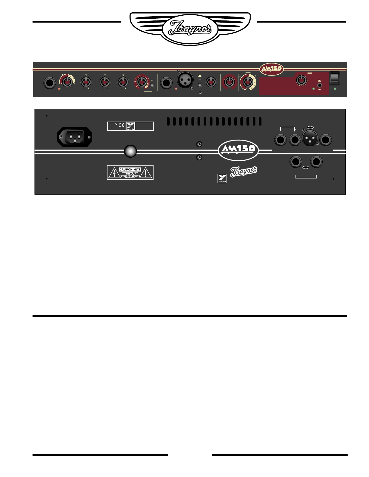
POWER Switch & Indicator
Depress the top or bottom of the POWER switch on the
far right side of the control panel to turn the AM150 on or
off. The green LED located under the power switch will
illuminate when the unit is on.
Channel 1 (Acoustic Guitar)
INPUT Jack
This is unbalanced with an impedance of 1 meg-ohm
and can accept either passive or active pickups (piezo/
coil).
GAIN Control
Adjust this control for the desired volume. Check the
CLIP LED for activity – see below.
LOW, MID & HIGH EQ
+/-15dB of equalization is provided for precise tone
shaping of the instrument. Center position is neutral,
turn right to boost frequency gain and left to reduce it.
See under CLIP LED for additional information. This EQ
does NOT affect Channel 2.
Notch Filter
This represents a fixed-depth dip or notch in frequency
response, which can be moved across the sound
spectrum with the FREQuency control to either attenuate
feedback or enhance the sound of your particular
instrument. If feedback occurs, make sure that the
NOTCH button is depressed, then rotate the FREQuency
control slowly until the feedback is reduced or eliminated.
Please note that if feedback occurs when you are in
close proximity to the AM150, the notch filter may not be
1

A
C
O
U
S
T
I
C
M
A
S
T
E
R
able to stop all of it. Reduce volume, reduce the LOW,
MID or HIGH EQ control setting or move the guitar
farther away from amplifier to defeat the feedback.
Clip LED
This feature can be used to gauge input level to avoid
audible clipping. If it begins flashing you have turned up the
GAIN, one or more of the EQ controls and/or the instrument
to the point where the amplifier is running out of power
headroom. Do not turn up further or distortion can occur.
Channel 2 (General Purpose)
Inputs
This channel’s ¼-inch INPUT jack accepts line level
signals, e.g. from a **CD player, a tape deck or a mixer.
Alternatively it can accept any guitar with active pickups
(i.e. with a built-in preamp), or any keyboard instrument.
It is balanced Tip (+), Ring (-), Sleeve, however it also
accepts unbalanced cables. For best results and to
reduce noise, it is advised that you use balanced cables
wherever possible. The 3-pin XLR INPUT connector
accepts any low-impedance dynamic microphone.
Alternatively it can be used as a balanced line-level
input, perhaps from a mixer’s monitor or auxiliary output.
**To connect a stereo source to the ¼-inch input of Channel 2’s
input, use an appropriate adapter, which terminates in a male ¼-
inch stereo plug (e.g. dual female RCA to ¼-inch male stereo).
Do not use both the ¼-inch and XLR inputs on Channel 2 at the
same time, signals will be highly attenuated!!
EFFECTS MASTER Control (dry/wet) and EFX
FOOTSWITCH jack
The control increases or decreases the intensity of
internal effects (note, it does not regulate the intensity
of any external effects which might be connected to
channel 2). An optional footswitch plugged into the EFX
FOOTSWITCH jack on the back panel may be used to
activate or bypass the internal effects (only).
MASTER Volume
This control is used to increase or decrease the acoustic
output of the AM150. It has no effect on the line out
signal level or the Channel 2 effects send.
DIGITAL EFFECTS System
There are 32 digital effects presets altogether divided
into BANK A and BANK B with 16 presets in each.
The banks are selectable via a pushbutton on the front
panel of the amp near the POWER switch. When the
button is in, BANK A is selected and the amber LED
nearby illuminates. In the out position, Bank B is enabled
and the light goes out. To select a specific effect, use
the PRESETS control. A numeric selection of each
preset and its description is located on the front panel
of the AM150. Additionally an Effects Table with brief
descriptions for the presets is located near the end of
this Owner’s Manual. A FOOTSWITCH jack on the back
panel accepts a standard footswitch, eg our model TFS1, to turn the effects system on and off.
EFX Loop - General
Channel 2 can be sent to the AM150’s internal digital
effects system via the EFFECTS Defeat /Active
pushbutton (active in the down position). However this
channel can also be connected to an external effects unit
and/or a graphic equalizer (Channel 2 is not affected by
Channel 1’s EQ or Notch filter hence some equalization
may be desired for certain instruments or other signal
sources). Internal effects and loop-connected effects, EQ,
etc. can be run at the same time on this channel (only).
EFX Send
This unbalanced ¼-inch output is located on the back
panel. Connect it to the input of the external effects unit
or EQ with a standard unbalanced shielded patch cable.
EFX Return
This unbalanced ¼-inch input is also located on the back
panel. Connect it to the output of the external effects unit
or EQ with a standard unbalanced shielded patch cable.
Mono BALanced LINE OUT (XLR)
This line out is post channel 1 and 2 but pre-effects and
pre-master volume. In other words the channel gain
controls and Channel 1’s tone controls do affect the
output signal, but the effects master and master volume
do not. Also, no external effects connected to channel
2’s EFX are present on the signal, i.e. it is dry. You
would use this output to directly connect the AM150 to
a mixer in any situation where effects are not desired on
the line out signal.
LEFT (Mono) & RIGHT Balanced POST EFX
LINE OUT Jacks (1/4-inch)
These are post-effects (i.e. wet) and would be used for
delivering signal to a mixer or amplifier when effects
are desired on the line out signal. Using Balanced or
unbalanced shielded cables, connect one or both of these
jacks to the input(s) on your mixer. If there is only a single,
mono input on the mixer, use the LEFT/MONO jack.
2
 Loading...