

Page 1

Trapeze
Mobility Point
™
MP-372 Installation Guide
Part Number
730-9502-0052, Revision C
Page 2

Trapeze Networks, Inc.
5753 W. Las Positas Blvd.
Pleasanton, CA 94588
Tel: +1 925-474-2200
Fax: +1 925-251-0642
Toll-Free: 877-FLY-TRPZ (877-359-8779)
www.trapezenetworks.com
© 2005 Trapeze Networks, Inc. All rights reserved.
Trademarks
Trapeze Networks, the Trapeze Networks logo, the Trapeze Networks flyer icon, Mobility System, Mobility
Exchange, MX, Mobility Point, MP, Mobility System Software, MSS, RingMaster, AAA Integration and
RADIUS Scaling, ActiveScan, AIRS, Bonded Auth, FastRoaming, Granular Transmit Power Setting, GTPS,
GuestPass, Layer 3 Path Preservation, Location Policy Rule, LPR, Mobility Domain, Mobility Profile,
Passport-Free Roaming, SentryScan, Time-of-Day Access, TDA, TAPA, Trapeze Access Point Access
Protocol, Virtual Private Group, VPG, Virtual Service Set, Virtual Site Survey and WebAAA are trademarks
of Trapeze Networks, Inc. Trapeze Networks SafetyNet is a service mark of Trapeze Networks, Inc. All other
products and services are trademarks, registered trademarks, service marks or registered service marks of their
respective owners.
Disclaimer
All statements, specifications, recommendations, and technical information are current or planned as of the
date of the publication of this document. They are reliable as of the time of this writing and are presented
without warranty of any kind, expressed or implied. In an effort to continuously improve the product and add
features, Trapeze Networks reserves the right to change any specifications contained in this document without
prior notice of any kind.
Comments and Feedback
Your feedback on Trapeze documentation is important to us. Send any comments and suggestions to
For the most current version of this document, see www.trapezenetworks.com.
Note. The manufacturer is not responsible for any radio or TV interference
caused by unauthorized modifications to this equipment. Such modifications
could void the user’s authority to operate the equipment.
ii
Page 3

Customer Service
For general information about Trapeze Networks Mobility System™ products and
services, visit www.trapezenetworks.com. For warranty, license, and support
information, visit the following sites:
● Warranty and software licenses. Current Trapeze Networks warranty and
software licenses are available at www.trapezenetworks.com/services/
warranty.asp.
● Support services. For information about Trapeze support services, visit
www.trapezenetworks.com/services/. Or call 1-866-877-9822 (in the US or
Canada) or +1 925-474-2400 and select option 5.
Note. TRAPEZE NETWORKS SELLS AND SERVICES ITS PRODUCTS PRIMARILY
THROUGH ITS AUTHORIZED RESELLERS AND DISTRIBUTORS. If you purchased
your product from an authorized Trapeze reseller or distributor and do not have
a service contract with Trapeze Networks, you must contact your local reseller
or distributor for technical assistance.
Contacting the Technical Assistance Center
Contact the Trapeze Networks Technical Assistance Center (TAC) by telephone,
email, or fax. If you have a service contract or are a Trapeze Authorized Partner,
log in to www.trapezenetworks.com/services/sup_programs.asp for more help.
● Within the US and Canada, call 1-866-TRPZTAC (1-866-877-9822).
● Within Europe, call +31 35 64 78 193.
● From locations outside the US and Canada, call +1 925-474-2400.
● In non-emergencies, send email to [email protected].
● When your case is active, you can fax more information to +1 925-474-2423.
iii
Page 4

TAC Response Time
TAC responds to service requests as follows:
Contact
method Priority Response time
Telephone Emergency One hour
Non-emergency Next business day
Email Non-emergency Next business day
Information to Have Available
To expedite your service request, have the following information available when
you call or write to TAC for technical assistance:
● Your company name and address
● Your name, telephone number, cell phone or pager number, and email address
● Name, model, and serial number of the product(s) requiring service
● Software version and release number
iv
● Output of the show tech-support command
● Wireless client information
● License levels for RingMaster™ and Mobility Exchange™ (MX™) products
● Description of the problem and status of the troubleshooting effort
Trapeze Mobility Point Installation Guide
Page 5

Contents
Customer Service . . . . . . . . . . . . . . . . . . . . . . . . . . . . . . . . . . . . . . . . . . . . . . . . . . . . iii
1 Introducing the Trapeze Networks Mobility System . . . . . . . . . . . . . . . . 1
Trapeze Networks Mobility System . . . . . . . . . . . . . . . . . . . . . . . . . . . . . . . . 1
Documentation . . . . . . . . . . . . . . . . . . . . . . . . . . . . . . . . . . . . . . . . . . . . . . . . 2
Safety and Advisory Notices . . . . . . . . . . . . . . . . . . . . . . . . . . . . . . . . . . 4
Text and Syntax Conventions . . . . . . . . . . . . . . . . . . . . . . . . . . . . . . . . . 5
2 MP Overview . . . . . . . . . . . . . . . . . . . . . . . . . . . . . . . . . . . . . . . . . . . . . . . . . . . . . . . 7
External Hardware Features . . . . . . . . . . . . . . . . . . . . . . . . . . . . . . . . . . . . . . 8
Cable Ports . . . . . . . . . . . . . . . . . . . . . . . . . . . . . . . . . . . . . . . . . . . . . . . . 9
External Antenna Connectors . . . . . . . . . . . . . . . . . . . . . . . . . . . . . . . . 10
Kensington Security Slot . . . . . . . . . . . . . . . . . . . . . . . . . . . . . . . . . . . . 12
MP Mounting Options . . . . . . . . . . . . . . . . . . . . . . . . . . . . . . . . . . . . . . 12
Status LEDs . . . . . . . . . . . . . . . . . . . . . . . . . . . . . . . . . . . . . . . . . . . . . . 12
Connection Options . . . . . . . . . . . . . . . . . . . . . . . . . . . . . . . . . . . . . . . . . . . 14
3 Installing and Connecting an MP-372 . . . . . . . . . . . . . . . . . . . . . . . . . . . . . 15
Unpacking an MP . . . . . . . . . . . . . . . . . . . . . . . . . . . . . . . . . . . . . . . . . . . . . 16
Installation Requirements and Recommendations . . . . . . . . . . . . . . . . . . . . 18
RingMaster Network Plan and Work Orders . . . . . . . . . . . . . . . . . . . . . 18
MX Switch Recommendation . . . . . . . . . . . . . . . . . . . . . . . . . . . . . . . . 18
Wall Installation Recommendations . . . . . . . . . . . . . . . . . . . . . . . . . . . 19
MP Radio Safety Advisories . . . . . . . . . . . . . . . . . . . . . . . . . . . . . . . . . 19
Radio Frequency Exposure . . . . . . . . . . . . . . . . . . . . . . . . . . . . . . . 19
Additional Radio Safety Advisories . . . . . . . . . . . . . . . . . . . . . . . . 19
Cable Requirements . . . . . . . . . . . . . . . . . . . . . . . . . . . . . . . . . . . . . . . . 20
Installing an MP-372 . . . . . . . . . . . . . . . . . . . . . . . . . . . . . . . . . . . . . . . . . . 22
Installation Hardware and Tools . . . . . . . . . . . . . . . . . . . . . . . . . . . . . . 22
Suspended Ceiling Installation—Flush Ceiling Tiles . . . . . . . . . . . . . . 24
Suspended Ceiling Installation—Drop Ceiling Tiles . . . . . . . . . . . . . . . 30
Contents
v
Page 6

Junction Box Installation . . . . . . . . . . . . . . . . . . . . . . . . . . . . . . . . . . . . 36
Solid Wall or Ceiling Installation . . . . . . . . . . . . . . . . . . . . . . . . . . . . . 40
Tabletop Installation . . . . . . . . . . . . . . . . . . . . . . . . . . . . . . . . . . . . . . . 45
Connecting an MP to an External Antenna . . . . . . . . . . . . . . . . . . . . . . 49
Connecting an MP to an MX Switch . . . . . . . . . . . . . . . . . . . . . . . . . . . . . . 50
Verifying MP Health . . . . . . . . . . . . . . . . . . . . . . . . . . . . . . . . . . . . . . . . . . 52
A MP Troubleshooting. . . . . . . . . . . . . . . . . . . . . . . . . . . . . . . . . . . . . . . . . . . . . . . 53
B MP Technical Specifications . . . . . . . . . . . . . . . . . . . . . . . . . . . . . . . . . . . . . . . 55
C Translated Warning Conventions and Warnings . . . . . . . . . . . . . . . . . . . 61
Index. . . . . . . . . . . . . . . . . . . . . . . . . . . . . . . . . . . . . . . . . . . . . . . . . . . . . . . . . . . . . . . . 69
vi
Trapeze Mobility Point Installation Guide
Page 7

Introducing the Trapeze Networks Mobility System
Trapeze Networks Mobility System . . . . . . . . . . . . . . . . . . . . . . . . . . . . . . . . . 1
Documentation . . . . . . . . . . . . . . . . . . . . . . . . . . . . . . . . . . . . . . . . . . . . . . . . . 2
This guide shows you how to install a Trapeze Networks™ Mobility Point™
(MP™) access point in a Trapeze Networks Mobility System™ wireless LAN
(WLAN).
Read this guide if you are a network administrator or other person installing MP
access points in a network.
1
Trapeze Networks Mobility System
The Trapeze Networks Mobility System is an enterprise-class WLAN solution
that seamlessly integrates with an existing wired enterprise network. The Trapeze
system provides secure connectivity to both wireless and wired users in large
environments such as office buildings, hospitals, and university campuses.
The Trapeze Mobility System fulfills the three fundamental requirements of an
enterprise WLAN: It eliminates the distinction between wired and wireless
networks, allows users to work safely from anywhere (secure mobility), and
provides a comprehensive suite of intuitive tools for planning and managing the
network before and after deployment, greatly easing the operational burden on IT
resources.
Introducing the Trapeze Networks Mobility System
1
Page 8

Documentation
Chapter 1
The Trapeze Networks Mobility System consists of the following components:
● RingMaster tool suite—A full-featured graphical user interface (GUI) client
application used to plan, configure, and deploy a WLAN and its users. It also
provides a centralized service application for WLAN and user monitoring,
reporting, and diagnostics
● One or more Mobility Exchange™ (MX™) switches—Distributed,
intelligent machines for managing user connectivity, connecting and
powering Mobility Point (MP) access points, and connecting the WLAN to
the wired network backbone
● Multiple Mobility Point™ (MP™) access points—Wireless access points
(APs) that transmit and receive radio frequency (RF) signals to and from
wireless users and connect them to an MX switch
● Mobility System Software™ (MSS™)—The operating system that runs all
MX switches and MP access points in a WLAN, and is accessible through a
command-line interface (CLI), the Web View interface, or the RingMaster
GUI
Documentation
Consult the following documents to plan, install, configure, and manage a Trapeze
Networks Mobility System.
Planning, Configuration, and Deployment
Trapeze RingMaster User’s Guide. Instructions for planning, configuring,
deploying, and managing the entire WLAN with the RingMaster tool suite. Read
this guide to learn how to plan wireless services, how to configure and deploy
Trapeze equipment to provide those services, and how to optimize and manage
your WLAN.
Trapeze RingMaster Reference Manual. Detailed instructions and information for
all RingMaster planning, configuration, and management features.
2
Trapeze Mobility Point Installation Guide
Page 9

Documentation
Chapter 1
Installation
● Trapeze Mobility System Software Quick Start Guide. Instructions for
performing basic setup of secure (802.1X) and guest (Web AAA) access, for
configuring a Mobility Domain for roaming, and for accessing a sample
network plan in RingMaster for advanced configuration and management
● Trapeze Mobility Exchange Installation and Basic Configuration Guide.
Instructions and specifications for installing an MX switch in a Trapeze
Mobility System WLAN, and basic instructions for deploying a secure IEEE
802.11 wireless service
● Trapeze Mobility Point Installation Guide. Instructions and specifications for
installing an MP access point and connecting it to an MX switch
● Trapeze Regulatory Information. Important safety instructions and
compliance information that you must read before installing Trapeze
Networks products
Configuration and Management
● Trapeze RingMaster Reference Manual. Instructions for planning,
configuring, deploying, and managing the entire WLAN with the RingMaster
tool suite
● Trapeze Mobility System Software Configuration Guide. Instructions for
configuring and managing the system through the MSS CLI
● Trapeze Mobility System Software Command Reference. Functional and
alphabetic reference to all MSS commands supported on MX switches and
MP access points
Introducing the Trapeze Networks Mobility System
3
Page 10
Documentation
Chapter 1
Safety and Advisory Notices
The following kinds of safety and advisory notices appear in this manual. (For
translations of the warning conventions and of all warnings in this manual, see
Appendix C, “Translated Warning Conventions and Warnings,” on page 61.)
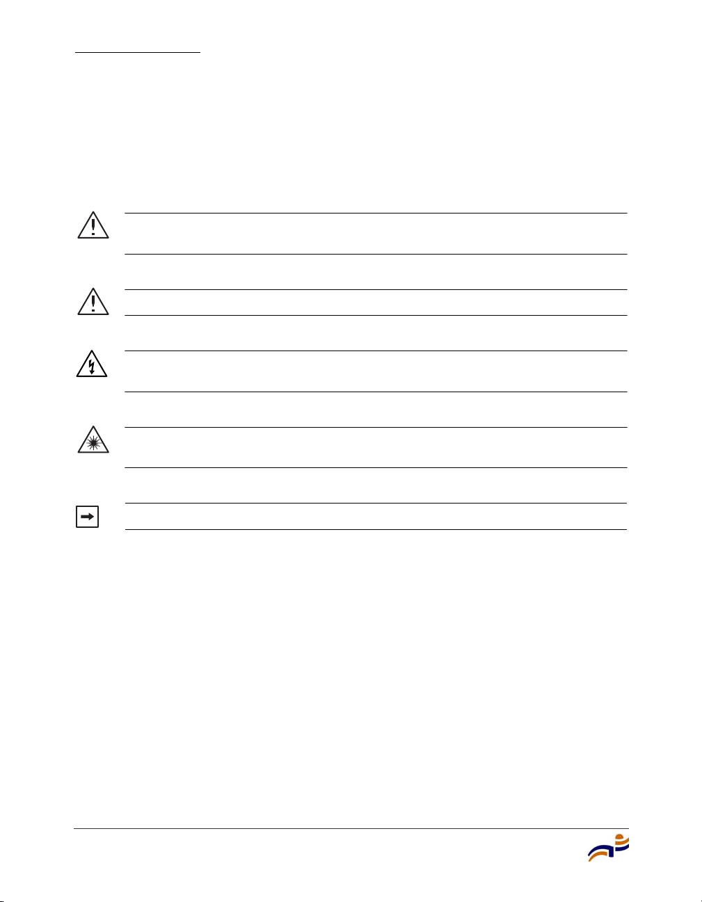
Caution! This situation or condition can lead to data loss or damage to the
product or other property.
Warning! This situation or condition can cause injury.
Warning! High voltage. This situation or condition can cause injury due to
electric shock.
Warning! Radiation. This situation or condition can cause injury due to
improper handling of fiber-optic equipment.
Note. This information is of special interest.
4
Trapeze Mobility Point Installation Guide
Page 11

Text and Syntax Conventions
Trapeze manuals use the following text and syntax conventions:
Convention Use
Monospace text Sets off command syntax or sample commands and
system responses.
Bold text Highlights commands that you enter or items you
select.
Italic text Designates command variables that you replace
with appropriate values, or highlights publication
titles or words requiring special emphasis.
Menu Name > Command Indicates a menu item that you select. For example,
File > New indicates that you select New from the
File menu.
[ ] (square brackets) Enclose optional parameters in command syntax.
{ } (curly brackets) Enclose mandatory parameters in command syntax.
| (vertical bar) Separates mutually exclusive options in command
syntax.
Documentation
Chapter 1
Introducing the Trapeze Networks Mobility System
5
Page 12

Documentation
Chapter 1
6
Trapeze Mobility Point Installation Guide
Page 13

MP Overview
External Hardware Features . . . . . . . . . . . . . . . . . . . . . . . . . . . . . . . . . . . . . . . 8
Connection Options . . . . . . . . . . . . . . . . . . . . . . . . . . . . . . . . . . . . . . . . . . . . . 14
A Trapeze Networks Mobility Point (MP) access point provides IEEE 802.11
wireless access to the network. MP access points are designed for use with a
Trapeze Networks Mobility Exchange (MX) switch. MP access points require
hardware installation only. All configuration for an MP access point takes place
on the MX switch.
This guide describes MP model MP-372. The MP-372 has one 802.11a radio and
one 802.11b/g radio. Both radios have internal diversity omnidirectional antennas.
In addition, both radios have separate jacks for attachment of optional external
sectorized or directional antennas. The antennas must be ordered separately.
2
Warning! Installation must be performed by qualified service personnel only.
Read and follow all warning notices and instructions marked on the product or
included in the documentation. Before installing the product, read the Trapeze
Regulatory Information document. (For translations of this warning, see
“Qualified Service Personnel Warning” on page 63.)
Note. The MP radios are disabled by default and can be enabled only by a
system administrator using the MX switch.
MP Overview
7
Page 14
External Hardware Features
Chapter 2
External Hardware Features
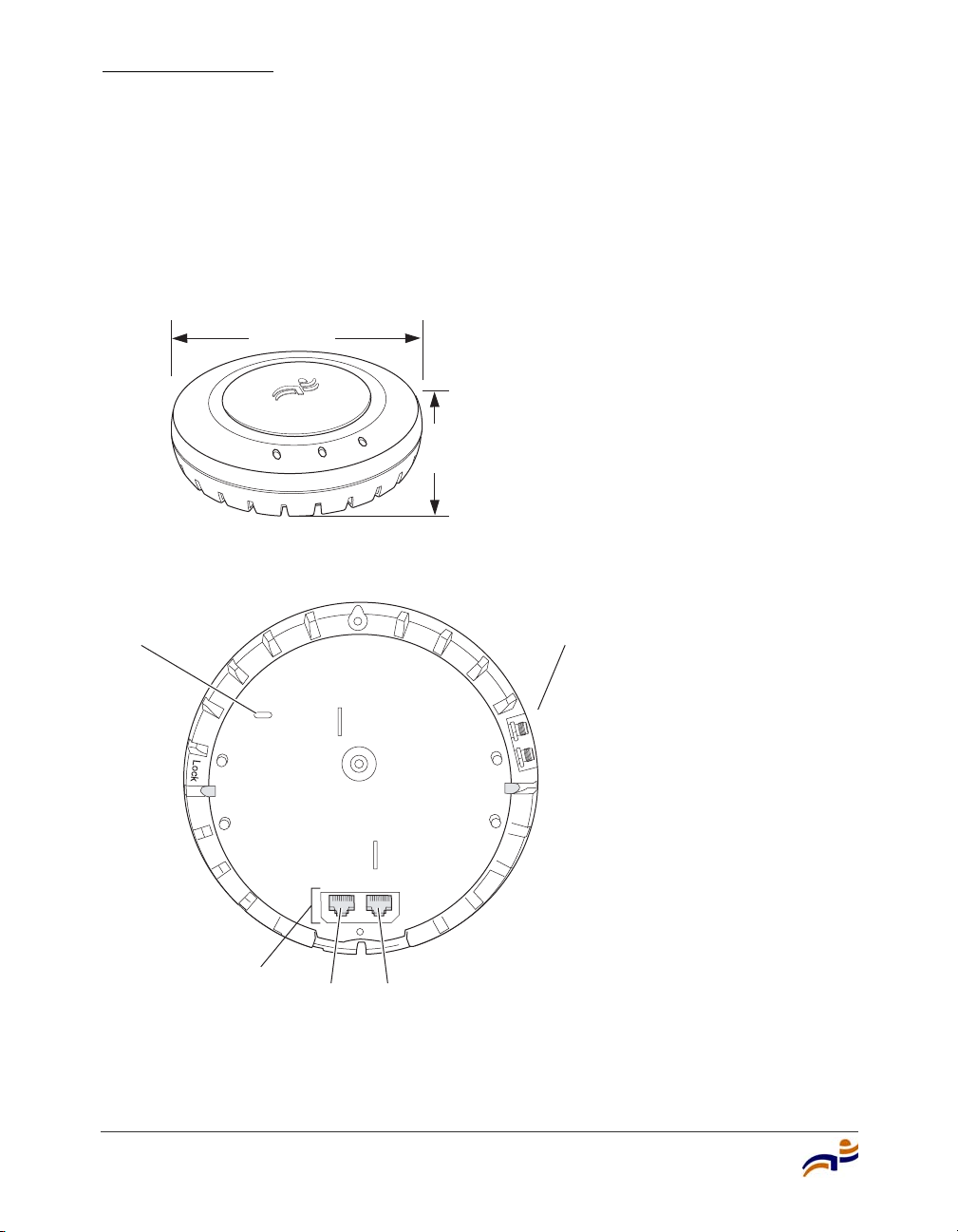
Figure 1 and Figure 2 show the external hardware features of the MP-372.
Figure 1. MP Access Point Model MP-372—Top View
Diameter
16.76 cm
(6.6 inches)
Height
4.69 cm
(1.85 inches)
840-9502-0040
Figure 2. MP Access Point Model MP-372—Bottom View
Kensington security
slot
8
RJ-45
ports
External antenna
connectors
802.11a
802.11b/g
Unlock
840-9502-0007
Port 2 Port 1
Trapeze Mobility Point Installation Guide
Page 15

Cable Ports
The MP-372 has two RJ-45 ports. (See Figure 2.) Each port provides a
10/100BASE-TX Ethernet connection to an MX switch. The connection can be
direct to an MX-switch or indirect through an intermediate Layer 2 or Layer 3
network.
The MP receives power and data through the RJ-45 ports. Use a Category 5
(Cat 5) cable with straight-through signaling and standard RJ-45 connectors to
connect an MP to an MX switch or other device in the network. The MP-372
supports 802.3af, and also can receive PoE from Trapeze switches and
Trapeze-approved power injectors. (See the Release Notes for Trapeze Networks
Mobility Point Access Points.)
The two RJ-45 ports support dual-homed configurations for redundancy. An MP
uses only one link for booting, configuration, and data transfer. If the link
becomes unavailable, the MP can reboot using the other link. The ports are
identical except for logical numbering (1 or 2). You can use either port to connect
an MP access point to an MX switch. However, an MP always attempts to boot on
MP port 1 first. Only if the boot attempt on port 1 fails does the MP attempt to
boot on port 2. If one port becomes unavailable, the other port can provide full
power to the MP.
External Hardware Features
Chapter 2
Note. MP access points do not support daisy-chain configurations. Do not
connect the MP access point to another MP access point.
MP Overview
9
Page 16

External Hardware Features
Chapter 2
External Antenna Connectors
The MP-372 has connectors for attaching optional external antennas. (See
Figure 2.) Table 1 lists the external antenna models.
Table 1. Trapeze External Antenna Models
Model Type Gain
ANT-5060
(ASTN6S)
ANT-5120
802.11a 14.5 dBi 60° 14°
1
802.11a 12.5 dBi 120° 14°
Horizontal Vertical
Beamwidth
(ASTN6T)
ANT-5180
802.11a 10.8 dBi 180° 14°
(ASTN6H)
ANT-1060 802.11b/g 10 dBi 60° 65°
ANT-1120 802.11b/g 7 dBi 120° 60°
ANT-1180 802.11b/g 6 dBi 180° 40°
1. The numbers in parentheses are the numbers that appear on the back of an 802.11a antenna’s reflector plate.
To verify an 802.11a external antenna’s model number, look for the number in parentheses.
Note. The MP-372 radios are certified for use only with these external
antennas.
10
Figure 3 shows the 802.11b/g antennas.
Trapeze Mobility Point Installation Guide
Page 17
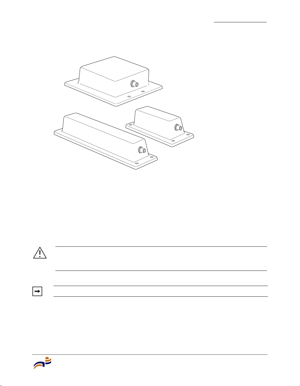
Figure 3. External 802.11b/g Antennas
Model ANT-1060
External Hardware Features
Chapter 2
Model ANT-1120
Model ANT-1180
840-9502-0077
The 802.11a external antennas look similar to the 802.11b/g model ANT-1180, but
each has a reflector plate specific to the model number. You can identify an
802.11a external antenna’s model by looking on the back of its reflector plate. Do
not reverse or remove the reflector plate. It is required for antenna operation.
Each antenna comes with a connector cable, mounting hardware, and installation
instructions.
Caution! The external connectors on the MP are labeled: 11B/G and 11A.
Each connector is a standard SMA connector. Make sure you attach the
antenna to the correct connector.
Note. Operation in the band 5.15–5.25 Ghz is restricted to indoor use only.
MP Overview
11
Page 18
External Hardware Features
Chapter 2
Kensington Security Slot
Models MP-372 has a slot for attachment of a Kensington security cable. The
cable is not included with the MP but can be ordered separately.
MP Mounting Options
You can mount an MP access point on any of the following types of surfaces:
● Suspended T-bar ceiling
● Junction box
● Solid surface wall or ceiling
● Table top
Note. The solid surface mounting option requires Cat 5 cable that does not
have strain relief. The other mounting options can use Cat 5 cable with or
without strain relief.
Status LEDs
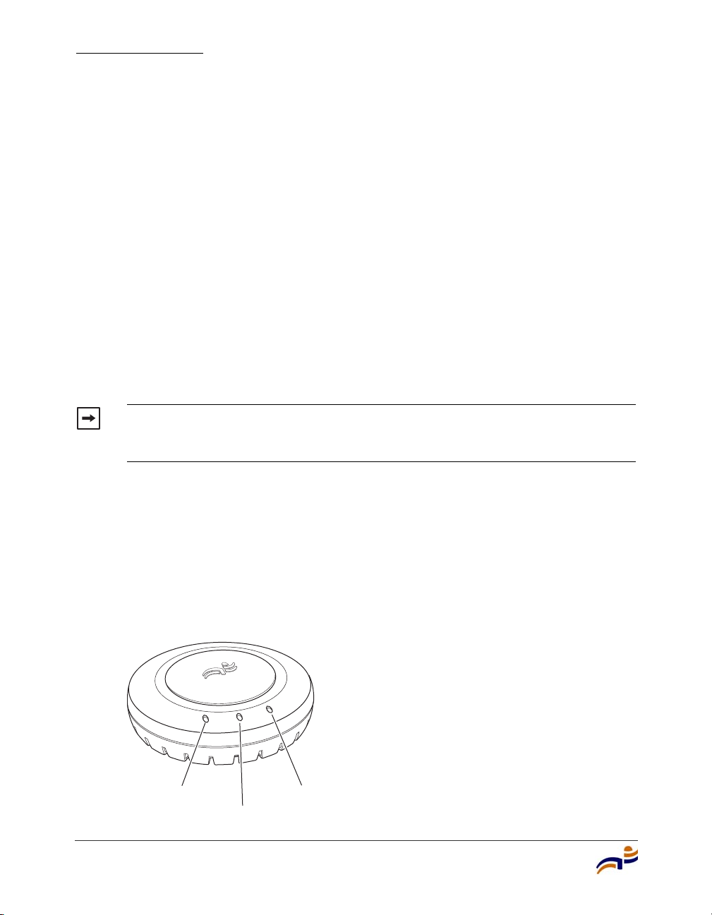
The MP has LEDs that provide status information for the device. Figure 4 shows
the locations of the LEDs. Table 2 describes the LEDs.
Figure 4. Health and Radio LEDs—MP-372
Radio 2 LED
Health LED
12
Radio 1 LED
840-9502-0010
Trapeze Mobility Point Installation Guide
Page 19

External Hardware Features
Table 2. MP Access Point LEDs—MP-372
LED Appearance Meaning
Health Solid green All the following are true:
• Management link with an MX switch is
operational.
• MP access point has booted.
• MP access point has received a valid
configuration from an MX switch.
• At least one radio is enabled or is in sentry
mode.
Solid amber MP access point is waiting to receive boot
instructions and a configuration file from an MX
switch.
Radio 1
Radio 2
Alternating green and
amber
Solid green A client is associated with the radio.
Blinking green Associated client is sending or receiving traffic.
MP access point is booting and receiving its
configuration file from an MX switch.
Blinking amber Non-associated client is sending or receiving
traffic.
Alternating green and
amber
Radio is unable to transmit. This state can occur
due to any of the following:
• Excessive radio interference in the
environment is preventing the radio from
sending beacons.
• The radio has failed.
Chapter 2
Unlit Means one of the following:
• Radio is disabled.
• Radio is enabled, but no clients are associated
with the radio and there is no traffic activity.
MP Overview
13
Page 20

Connection Options
Chapter 2
Connection Options
You can connect an MP access port directly to an MX switch port or indirectly to
MX switches through an intermediate Layer 2 or Layer 3 network. In either case,
use Category 5 (CAT 5) cable with straight-through signaling for each MP
connection.
You also can provide data link redundancy by connecting both of its ports directly
to MX switch ports or indirectly to MX switches through the network.
You can provide MX management redundancy even on a single MP Ethernet port
by connecting the MP indirectly to multiple MX switches through an intermediate
Layer 2 or Layer 3 network.
Note. Install the Cat 5 cables for the MP access point at the installation site
before installing the access point itself. During installation, you will insert the
Cat 5 cable(s) into the MP port(s) before attaching the access point to the
bracket.
14
Trapeze Mobility Point Installation Guide
Page 21

Installing and Connecting an MP-372
Unpacking an MP . . . . . . . . . . . . . . . . . . . . . . . . . . . . . . . . . . . . . . . . . . . . . . 16
Installation Requirements and Recommendations . . . . . . . . . . . . . . . . . . . . . 18
Installing an MP-372 . . . . . . . . . . . . . . . . . . . . . . . . . . . . . . . . . . . . . . . . . . . . 22
Connecting an MP to an MX Switch . . . . . . . . . . . . . . . . . . . . . . . . . . . . . . . 50
Verifying MP Health . . . . . . . . . . . . . . . . . . . . . . . . . . . . . . . . . . . . . . . . . . . . 52
Note. Before installing an MP access point, you might need to generate a
network plan and an MP work order with RingMaster. (See “RingMaster Network
Plan and Work Orders” on page 18.)
3
Installing and Connecting an MP-372
15
Page 22

Unpacking an MP
Chapter 3
Unpacking an MP
The shipping carton for an MP access point contains the following items:
● One MP access point
● Mounting kit:
● One universal mounting bracket (attached to the MP)
● One paper mounting template (used for marking cutting areas and screw
holes)
● One two-piece 14.2-mm (9/16-inch) T-bar clamp
● One two-piece 15.9-mm (5/8-inch) T-bar clamp
● One two-piece 23.9-mm (15/16-inch) T-bar clamp
● Two #6 sheet metal screws and two drywall anchors
● Three adhesive rubber feet
16
● One documentation pack that includes quick mounting instructions and a
registration card (not shown)
Trapeze Mobility Point Installation Guide
Page 23
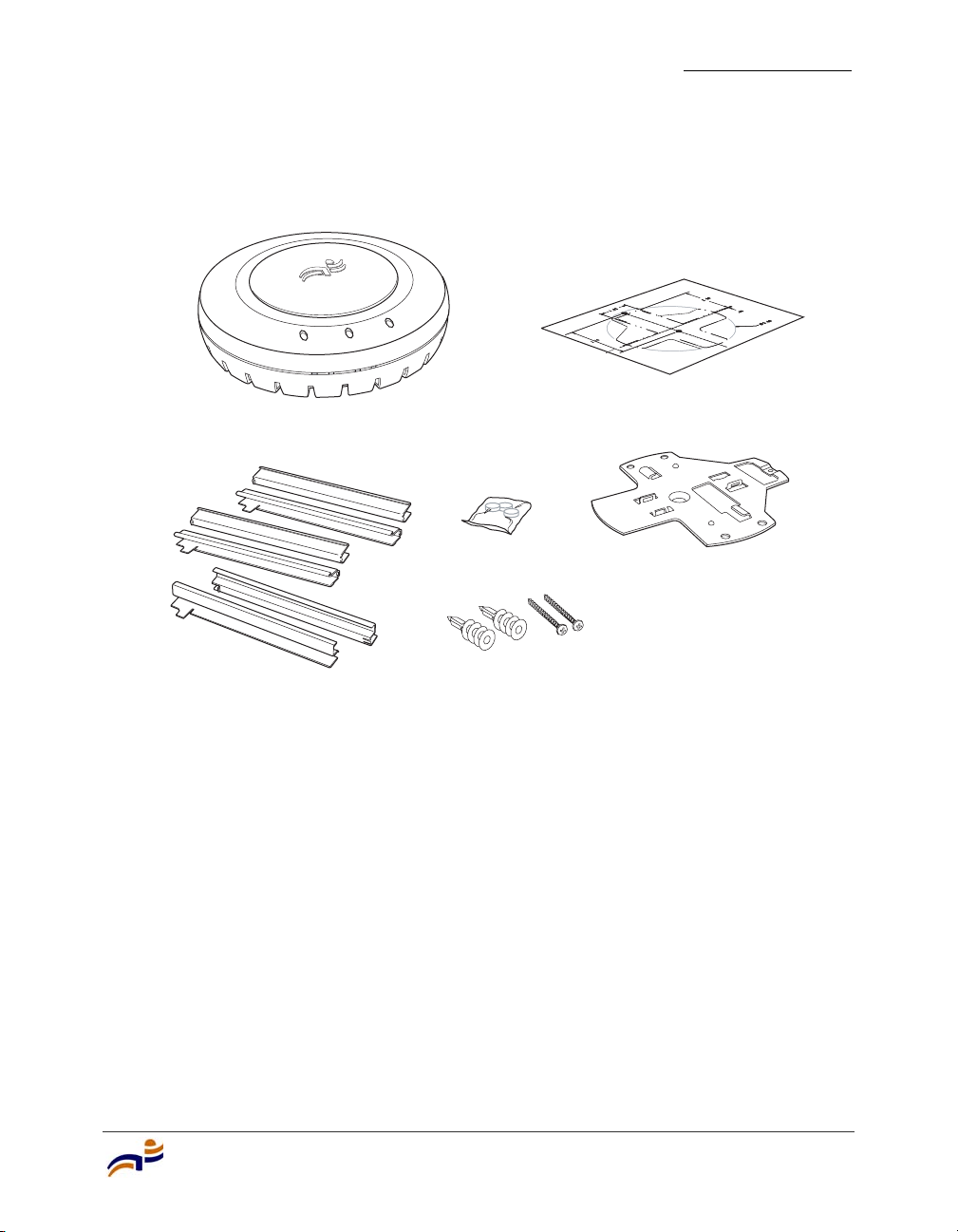
Figure 5 shows the contents of the shipping carton for model MP-372.
g
Figure 5. MP-372 Shipping Carton Contents
Mobility point
Unpacking an MP
Chapter 3
Mounting template
Universal
mounting bracket
840-9502-0001
T-bar clamps
Rubber feet
Mountin
hardware
Before you begin installation:
1 Open the carton and carefully remove the contents, if you have not already
done so.
2 Place the packing materials back in the carton and save the carton.
3 Verify that you received each item in the previous list. If any item is missing
or damaged, contact Trapeze Networks.
Installing and Connecting an MP-372
17
Page 24

Installation Requirements and Recommendations
Chapter 3
Installation Requirements and
Recommendations
For best results, follow these requirements and recommendations before installing
an MP access point.
RingMaster Network Plan and Work Orders
If you are using RingMaster to plan your Trapeze Networks Mobility System
installation, you might want to create and verify a network plan for the entire
Trapeze network installation and generate an MP work order, before installing MP
access points. A network plan and the MP work orders generated from it provide
the following information about MP access point installation and configuration:
● Number of MP access points required for adequate WLAN capacity in each
coverage area
● Detailed installation location for each MP access point
● Settings for all MP access points in the WLAN
(For information about installing RingMaster, creating and verifying a network
plan, and generating an MP work order, see the Trapeze RingMaster User’s Guide
and Trapeze RingMaster Reference Manual.)
MX Switch Recommendation
Trapeze Networks recommends that you install and configure the MX switch
before installing an MP access point. If the switch is already installed and
configured for the MP access point(s), you can immediately verify the cable
connection(s) when you plug the cable(s) into the MP access point.
Caution! MP model MP-372 is designed to receive power only from an
802.3af-compliant source, a Trapeze Networks Mobility Exchange (MX) switch,
or a Trapeze-approved power injector. Connecting an MP access point to a
Power over Ethernet (PoE) device that is not approved by Trapeze Networks
can damage the equipment.
18
Trapeze Mobility Point Installation Guide
Page 25

Installation Requirements and Recommendations
(For information about connecting an MP access point to an MX switch port, see
“Connecting an MP to an MX Switch” on page 50.)
Wall Installation Recommendations
If you plan to install an MP on a partial wall or other vertical surface, orient the
top of the access point (the side with the LEDs) toward the intended coverage
area. The radio antennas transmit through the top of the access point but not
through the bottom (where the bracket is).
This recommendation does not apply if you plan to use external antennas. You can
orient the antennas independently of the MP itself. Orient an external antenna to
face the intended coverage area.
MP Radio Safety Advisories
When you enable the MP radio(s) as part of MX switch configuration, the radios
are able to receive and transmit radio frequency energy as soon as you connect the
MP access point(s) to the MX switch, either directly or through the network.
Chapter 3
Radio Frequency Exposure
Federal Communications Commission (FCC) Docket 96-8 for Spread Spectrum
Transmitters specifies a safety standard for human exposure to radio frequency
electromagnetic energy emitted by FCC-certified equipment. When used with the
proper antennas (shipped in the product), Trapeze Networks MP access point
products meet the uncontrolled environmental limits found in OET-65 and
ANSI C95.1-1991. Proper installation of the MP access point according to the
instructions in this manual will result in user exposure that is below the FCC
recommended limits.
Additional Radio Safety Advisories
(For translations of warnings, see “Radio Safety Warnings” on page 64.)
Warning! In the U.S., locate the MP access point and any externally attached
antennas a minimum of 20 cm (7.9 inches) away from people. This safety
warning conforms with FCC radio frequency exposure limits for dipole antennas
such as those used in the MP access point.
Installing and Connecting an MP-372
19
Page 26
Installation Requirements and Recommendations
Chapter 3
Warning! Do not operate the MP access point near unshielded blasting caps
or in an otherwise explosive environment unless the device has been modified
for such use by qualified personnel.
Warning! Do not touch or move the MP access point when the antennas are
transmitting or receiving.
Warning! Do not hold any radio device so that the antenna is very close to or
touching the face, eyes, or other exposed body part while the device's radio
antenna is transmitting.
Warning! Before using a wireless device in a hazardous location, consult the
local codes, national codes, and safety directors of the location for usage
constraints.
Cable Requirements
Warning! Do not connect or disconnect cables or otherwise work with the MP
access point hardware during periods of lightning activity. (For translations of
this warning, see “Lightning Warning” on page 67.)
Note. The MP access point is intended for indoor use only. Do not install the
device outdoors, unless you install it in a properly installed Trapeze Networks
outdoor MP enclosure.
Note. To reduce the possibility of connection interference caused by dust,
clean the Cat 5 connector pins before inserting a cable into an MP access point.
20
Trapeze Mobility Point Installation Guide
Page 27

Installation Requirements and Recommendations
Cat 5 cable with straight-through signaling must be installed at the site before you
install an MP access point. A single connection requires one cable. A dual-homed
connection requires two cables.
Table 3 lists the pin signals for 10/100 Ethernet straight-through wiring. Pins 4, 5,
7, and 8 are used when Trapeze Power over Ethernet (PoE) is enabled on the port.
RD means Receive Data and TD means Transm it Data.
Table 3. 10/100 Ethernet Straight-Through Pin Signals
MX Switch Other Device
Pin Function Pin Function
1RD+1TD+
2RD-2TD-
3TD+3RD+
4 PoE+ 4 PoE+
5 PoE+ 5 PoE+
6TD-6RD-
7 PoE- 7 PoE-
Chapter 3
8 PoE- 8 PoE-
Mounting an MP access point on a solid surface requires Cat 5 cable that does not
have strain relief. For installation on all other surfaces, you can use Cat 5 cable
with or without strain relief.
(For more information about cables, see “Cable Ports” on page 9.)
Installing and Connecting an MP-372
21
Page 28

Installing an MP-372
Chapter 3
Installing an MP-372
To install an MP-372, use one of the procedures in this section.
Installation Hardware and Tools
Table 4 lists the mounting hardware and tools required for each type of
installation.
Table 4. Required Mounting Hardware and Tools—Model MP-372
Mounting Option Required Hardware and Tools
Suspended ceiling—flush
ceiling tiles
Mounting template Yes
Universal mounting bracket Yes
T-bar clamp
Note: A T-bar clamp is not required
for a 23.9-mm (15/16-inch) T-bar
ceiling with flush ceiling tiles.
Box cutter No
Small screwdriver (3-mm or
1/8-inch)
Suspended ceiling—drop
ceiling tiles
Mounting template Yes
Universal mounting bracket Yes
T-bar clamp Yes
Box cutter No
Small screwdriver (3-mm or
1/8-inch)
Included with the
Product
Ye s
No
No
22
Trapeze Mobility Point Installation Guide
Page 29

Installing an MP-372
Chapter 3
Table 4. Required Mounting Hardware and Tools—Model MP-372
Mounting Option Required Hardware and Tools
Included with the
Product
Junction box Junction box No
Two #6-32 x 1-inch machine screws Yes
Universal mounting bracket Yes
Small screwdriver (3-mm or
No
1/8-inch)
#2 Phillips-head screwdriver No
Solid wall or ceiling Two #6 sheet metal screws and two
Ye s
drywall anchors
Universal mounting bracket Yes
Hammer No
Small screwdriver (3-mm or
No
1/8-inch)
#2 Phillips-head screwdriver No
Tabletop Universal mounting bracket Yes
Three adhesive rubber feet Yes
Small screwdriver (3-mm or
No
1/8-inch)
Note. The MP-372 model is UL2043 plenum rated, so it also can be installed in
the space above the ceiling if preferred.
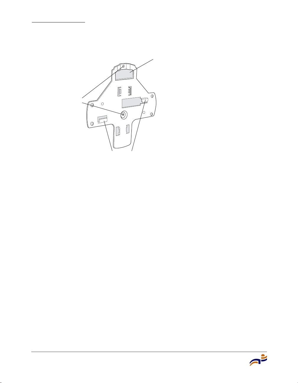
Figure 6 shows the universal mounting bracket.
Installing and Connecting an MP-372
23
Page 30
Installing an MP-372
g
Chapter 3
Figure 6. Universal Mounting Bracket
Port connector
opening
Screw holes
T-bar flan
es
840-9502-0018
Suspended Ceiling Installation—Flush Ceiling Tiles
(For required mounting hardware and tools, see Table 4 on page 22.)
1 Select an installation location that is centered over a T-bar in the ceiling.
2 Cut a hole as follows in the ceiling tile for the Cat 5 cable(s):
a Place the mounting template over the area where you plan to install the
MP access point.
b Use the box cutter to cut along the line marking the opening for the port
connectors.
c Remove the mounting template and the material you cut from the ceiling
panel.
3 Determine whether to install a T-bar clamp onto the ceiling T-bar:
● If the T-bar width is 14.2 mm (9/16 inches), you need to install the
14.2-mm (9/16-inch) T-bar clamp. Go to step 4.
● If the T-bar width is 23.9 mm (15/16 inches), the universal mounting
bracket fits directly onto the T-bar. Go to step 5.
24
Trapeze Mobility Point Installation Guide
Page 31
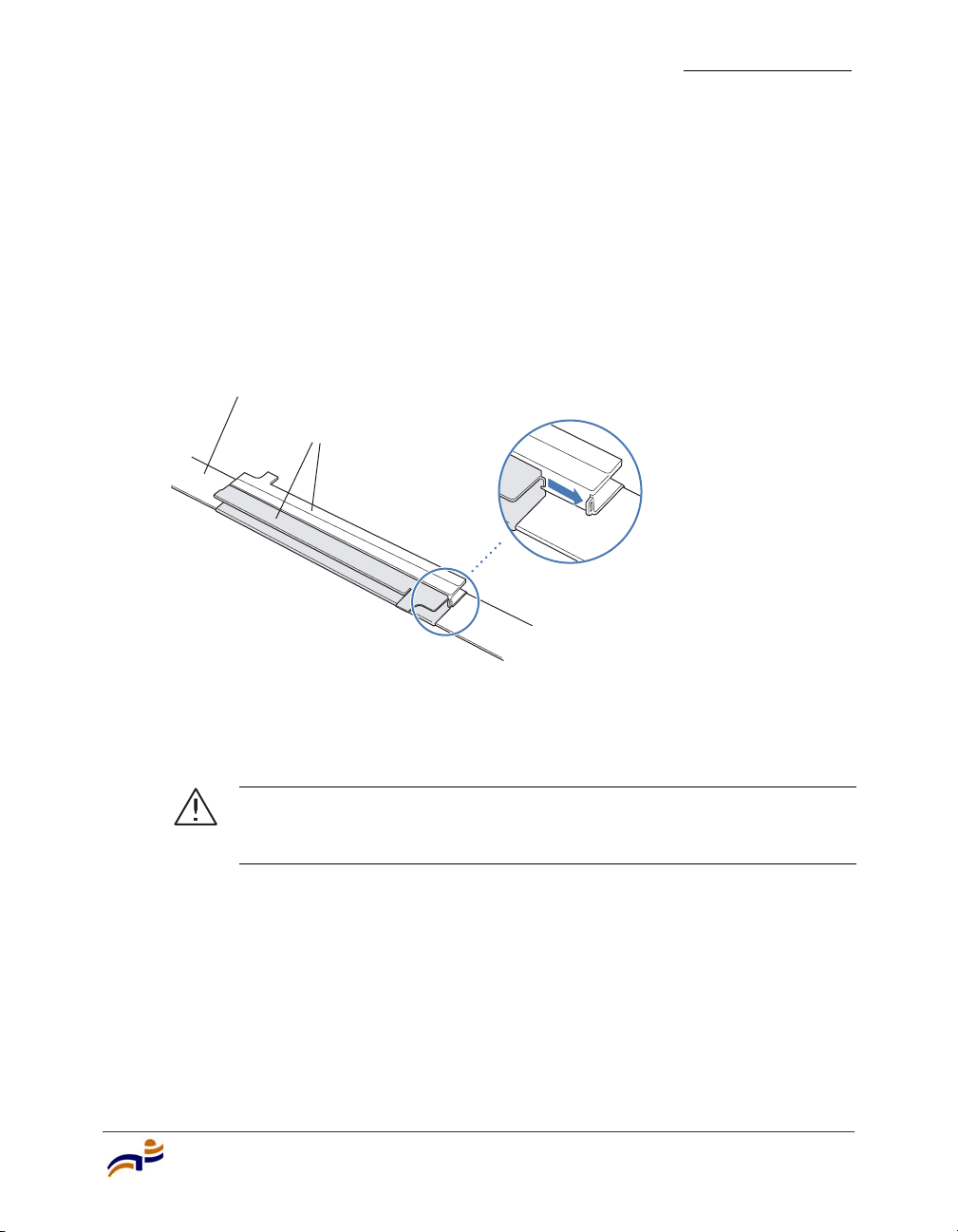
4 Install the 14.2-mm (9/16-inch) T-bar clamp onto the ceiling T-bar as shown
in Figure 7.
a Slide each half of the clamp onto the T-bar so that the clamp lip is fully on
the T-bar.
b Slide the two halves of the clamp toward each other until the tabs are
inserted completely into the holes and the clamp fits snugly on the T-bar.
Figure 7. Step 4—Installing a T-bar Clamp
Installing an MP-372
Chapter 3
T-bar
T-bar clamp halves
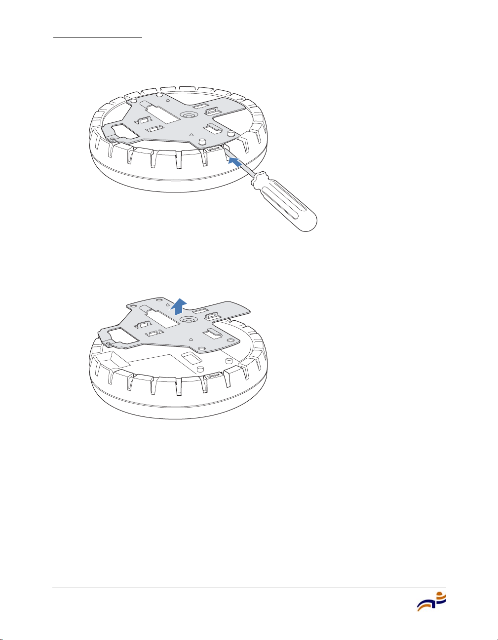
5 Unlock the universal mounting bracket from the MP access point by inserting
Slide together
840-9502-0003
the 3-mm or 1/8-inch screwdriver into the Unlock hole on the MP access point
as shown in Figure 8.
Caution! To avoid damage to the MP access point’s lock mechanism
or electronic components, do not use excessive force when inserting a
tool into the Unlock or Lock hole.
Installing and Connecting an MP-372
25
Page 32
Installing an MP-372
Chapter 3
Figure 8. Step 5—Unlocking the Bracket
6 Remove the bracket as shown in Figure 9.
Figure 9. Step 6—Removing the Bracket
840-9502-0011
26
840-9502-0008
7 Install the universal mounting bracket as follows onto the T-bar or T-bar
clamp:
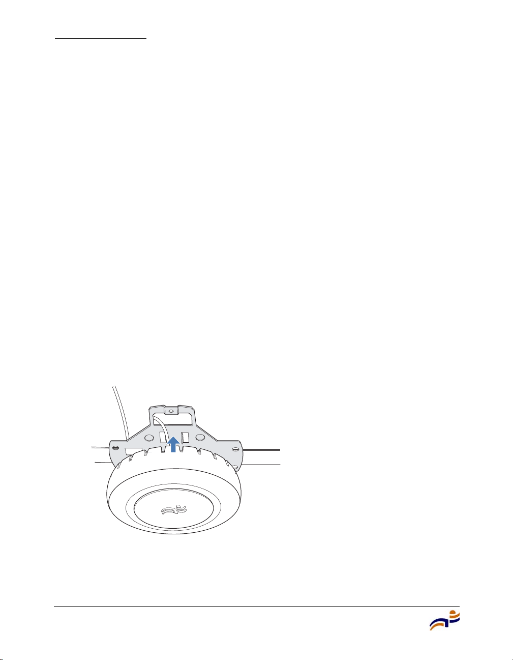
a As shown in Figure 10, place the universal mounting bracket against the
T-bar or clamp so that the two screw holes face downward and the two
T-bar flanges face upward and are adjacent to the T-bar edges.
Trapeze Mobility Point Installation Guide
Page 33
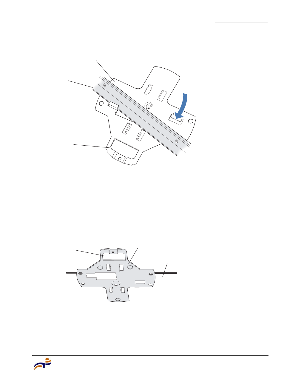
Figure 10. Step 7—Top View
Universal mounting
bracket
T-bar
Port connector
opening
Installing an MP-372
Chapter 3
(Viewed from above ceiling tiles, looking down.)
b Properly align the bracket for mounting by placing the bracket so that its
port connector opening is to the left of the hole you cut for the cables.
c Rotate the universal mounting bracket clockwise until the flanges snap
into place on the T-bar or clamp as shown in Figure 11.
Figure 11. Step 7—Bottom View
Port connector
opening
8 Pull the Cat 5 cable(s) about 15 cm (about 6 inches) out of the hole in the
Universal mounting bracket
ceiling tile and through the port connector opening to create enough slack to
insert the cable(s).
840-9502-0005
T- b a r
840-9502-0004
Installing and Connecting an MP-372
27
Page 34
Installing an MP-372
Chapter 3
9 Insert the Cat 5 cable(s) into the connector(s):
● For a single connection, use the connector for port 1.
● For redundancy, insert one cable into each connector.
10 Install the Kensington lock, if you plan to used one.
a Loop the Kensington lock’s cable around an object that cannot be moved
or damaged by a person pulling on the cable.
b Insert the key into the Kensington lock.
c Insert the Kensington lock into the security slot on the MP.
d Rotate the key right or left to secure the lock to the MP.
e Pull on the lock to verify that it is secured to the MP.
f Remove the key.
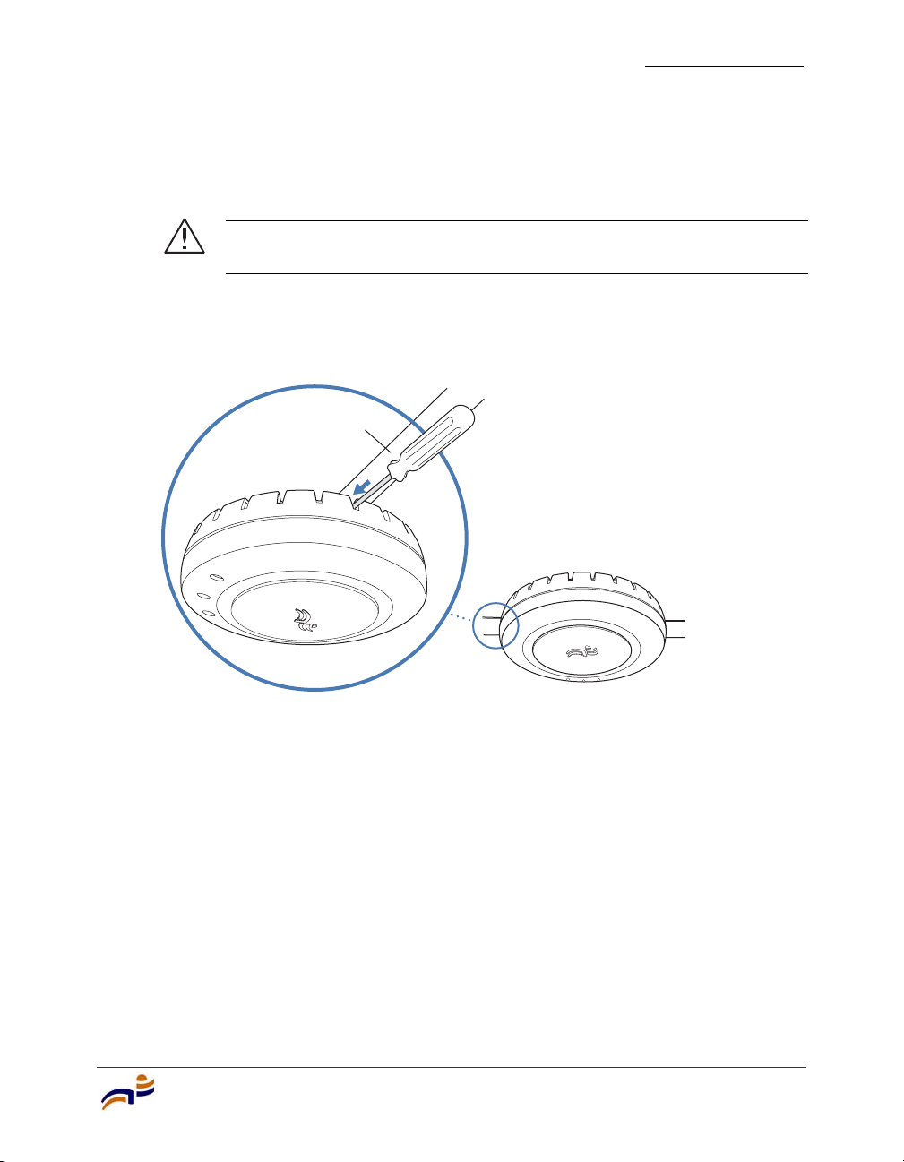
11 Lift the MP access point into place on the universal mounting bracket as
shown in Figure 12.
Make sure the cable feeds properly into the ceiling as you lift the device, and
does not become trapped between the access point and the bracket.
Figure 12. Step 10—Placing the MP Access Point on the Bracket
840-9502-0002
28
Trapeze Mobility Point Installation Guide
Page 35
12 Lock the MP access point onto the bracket by inserting the 3-mm or 1/8-inch
screwdriver into the Lock hole on the access point as shown in Figure 13.
Caution! To prevent possible damage to the MP access point, make
sure the device is fully locked onto the bracket before letting go of it.
Figure 13. Step 11—Locking the Bracket
L
o
ck
T-bar
Installing an MP-372
Chapter 3
840-9502-0006
13 To ensure that the MP access point is fully locked onto the bracket, gently pull
down on the access point and attempt to rotate it from side to side.
14 If the access point comes off the bracket, relock the device onto the bracket as
described in step 12 on page 29.
15 If the MP requires an external antenna, install and connect the antenna. (See
“Connecting an MP to an External Antenna” on page 49.)
16 If the other ends of the Cat 5 cable(s) are not already connected and the link
activated, go to “Connecting an MP to an MX Switch” on page 50. Otherwise,
go to “Verifying MP Health” on page 52.
Installing and Connecting an MP-372
29
Page 36
Installing an MP-372
Chapter 3
Suspended Ceiling Installation—Drop Ceiling Tiles
(For required mounting hardware and tools, see Table 4 on page 22.)
1 Select an installation location that is centered over a T-bar in the ceiling.
2 Cut a hole as follows in the ceiling tile for the Cat 5 cable(s):
a Place the mounting template over the area where you plan to install the
MP access point.
b Use the box cutter to cut along the line marking the opening for the port
connectors.
c Remove the mounting template and the material you cut from the ceiling
panel.
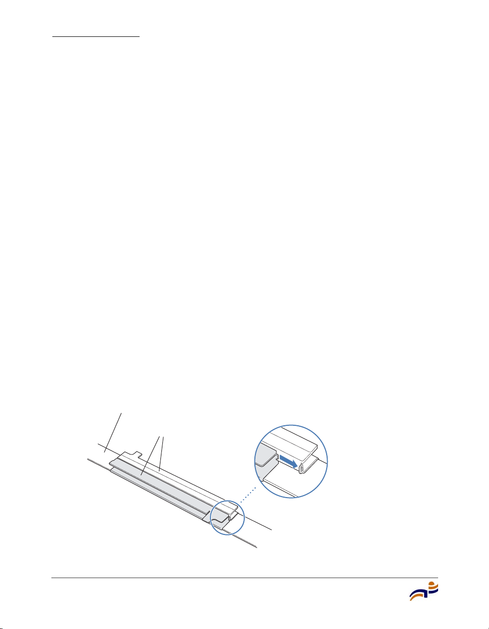
3 Install the T-bar clamp that fits the T-bar:
a Slide each half of the clamp onto the T-bar so that the clamp lip is fully on
the T-bar.
b Slide the two halves of the clamp toward each other until the tabs are
inserted completely into the holes and the clamp fits snugly on the T-bar.
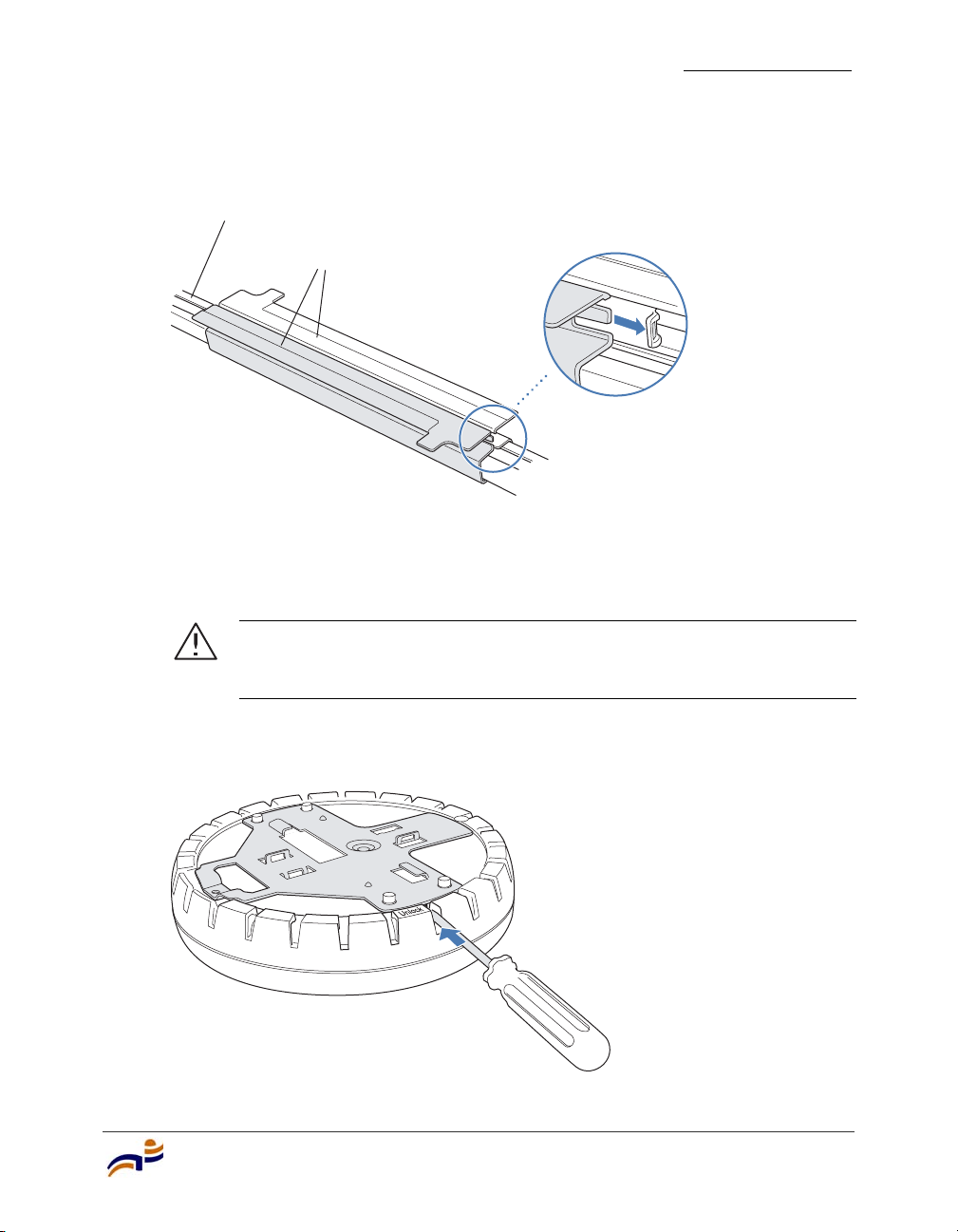
Figure 14 shows an example for a 23.9-mm (15/16-inch) T-bar. Figure 15
shows an example for a 15.9-mm (5/8-inch) T-bar.
Figure 14. Step 3—Installing the T-bar Clamp for a 23.9-mm
(15/16-inch) T-bar
30
T-bar
T-bar clamp halves
Trapeze Mobility Point Installation Guide
Slide together
840-9502-0003
Page 37
Installing an MP-372
Figure 15. Step 3—Installing the T-bar Clamp for a 15.9-mm
(5/8-inch) T-bar
T-bar
Slide together
T-bar clamp halves
840-9502-0066
4 Unlock the universal mounting bracket from the MP access point by inserting
the 3-mm or 1/8-inch screwdriver into the Unlock hole on the MP access point
as shown in Figure 16.
Chapter 3
Caution! To avoid damage to the MP access point’s lock mechanism
or electronic components, do not use excessive force when inserting a
tool into the Unlock or Lock hole.
Figure 16. Step 4—Unlocking the Bracket
Installing and Connecting an MP-372
840-9502-0011
31
Page 38
Installing an MP-372
Chapter 3
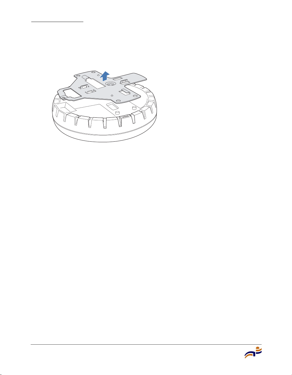
5 Remove the bracket as shown in Figure 17.
Figure 17. Step 5—Removing the Bracket
6 Install the universal mounting bracket as follows onto the T-bar clamp:
a As shown in Figure 18, place the universal mounting bracket against the
T-bar clamp so that the two screw holes face downward and the two T-bar
flanges face upward and are adjacent to the T-bar edges.
840-9502-0008
32
b Properly align the bracket for mounting by placing the bracket so that its
port connector opening is to the left of the hole you cut for the cables.
c Rotate the universal mounting bracket clockwise until the flanges snap
into place on the T-bar clamp as shown in Figure 19.
Trapeze Mobility Point Installation Guide
Page 39
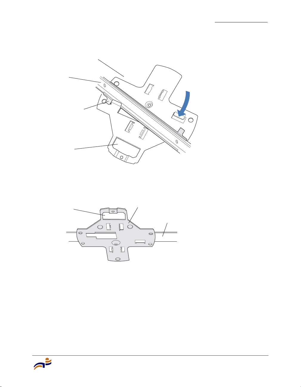
Figure 18. Step 6—Top View
Universal mounting
bracket
T- bar
T-bar clamps
(attached
to T-bar)
Port connector
opening
(Viewed from above ceiling tiles, looking down.)
Figure 19. Step 6—Bottom View
Installing an MP-372
Chapter 3
840-9502-0012
Port connector
opening
Universal mounting bracket
T- b a r
840-9502-0004
7 Pull the Cat 5 cable(s) about 15 cm (about 6 inches) out of the hole in the
ceiling tile and through the port connector opening to create enough slack to
insert the cable(s).
8 Insert the Cat 5 cable(s) into the connector(s):
● For a single connection, use the connector for port 1.
● For redundancy, insert one cable into each connector.
Installing and Connecting an MP-372
33
Page 40
Installing an MP-372
Chapter 3
9 Install the Kensington lock, if you plan to used one.
a Loop the Kensington lock’s cable around an object that cannot be moved
or damaged by a person pulling on the cable.
b Insert the key into the Kensington lock.
c Insert the Kensington lock into the security slot on the MP.
d Rotate the key right or left to secure the lock to the MP.
e Pull on the lock to verify that it is secured to the MP.
f Remove the key.
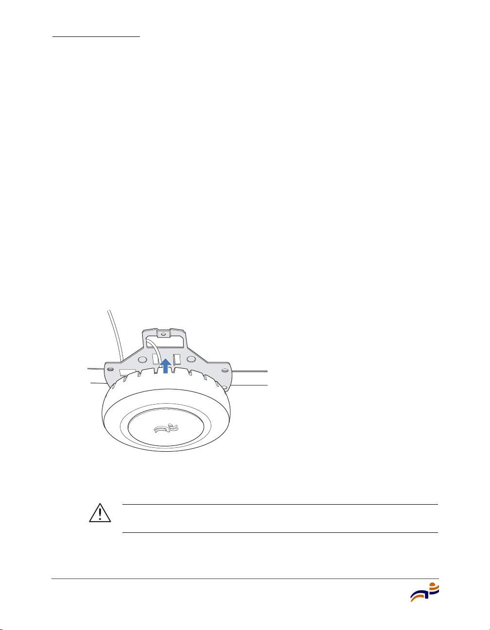
10 Lift the MP access point into place on the universal mounting bracket as
shown in Figure 20.
Make sure the cable feeds properly into the ceiling as you lift the device, and
does not become trapped between the access point and the bracket.
Figure 20. Step 9—Placing the MP Access Point on the Bracket
34
840-9502-0002
11 Lock the MP access point onto the bracket by inserting the 3-mm or 1/8-inch
screwdriver into the Lock hole on the access point as shown in Figure 21.
Caution! To prevent possible damage to the MP access point, make
sure the device is fully locked onto the bracket before letting go of it.
Trapeze Mobility Point Installation Guide
Page 41
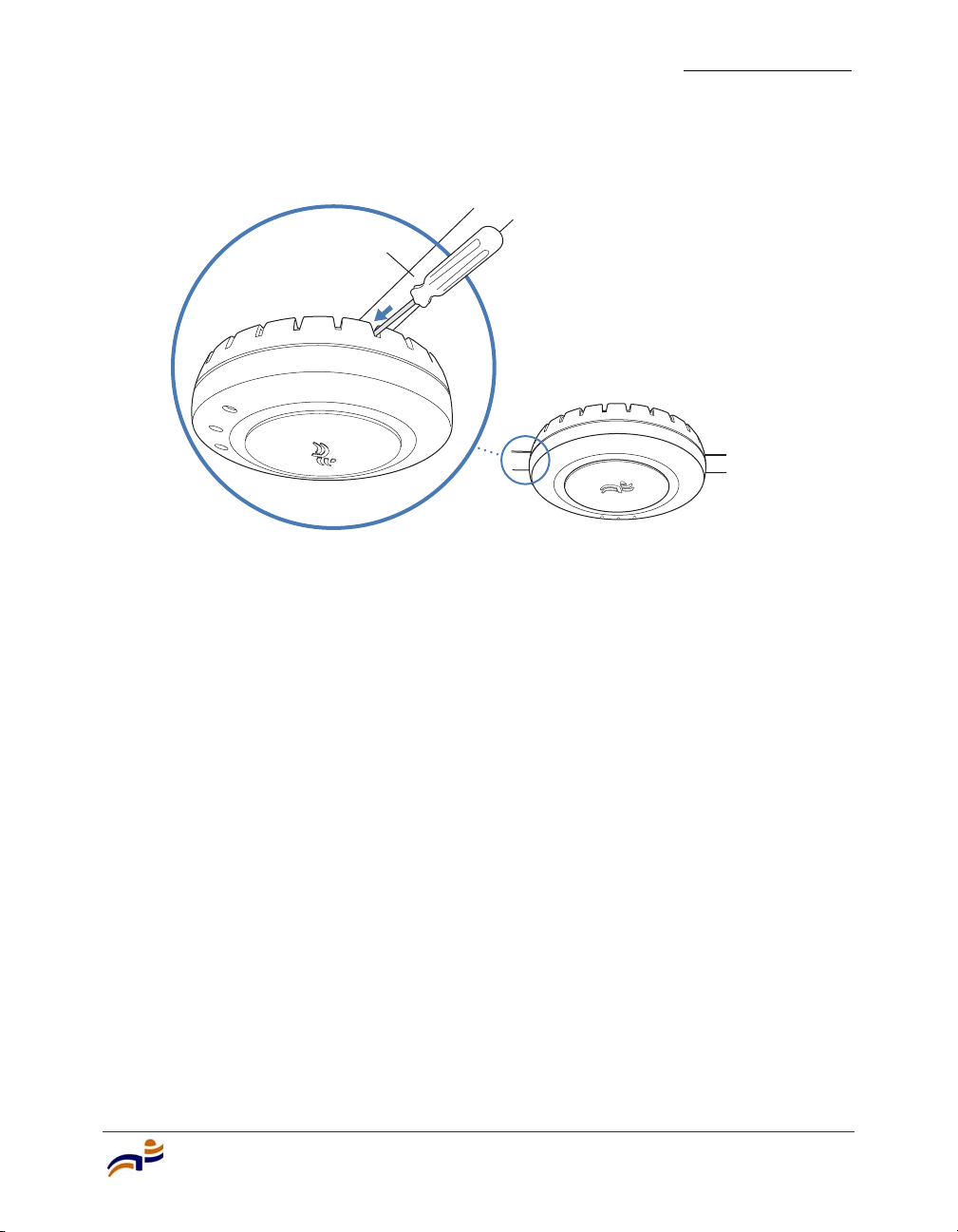
Figure 21. Step 10—Locking the Bracket
L
o
ck
T-bar
12 To ensure that the MP access point is fully locked onto the bracket, gently pull
down on the access point and attempt to rotate it from side to side.
Installing an MP-372
Chapter 3
840-9502-0006
If the access point comes off the bracket, relock the device onto the bracket as
described in step 11 on page 34.
13 If the MP requires an external antenna, install and connect the antenna. (See
“Connecting an MP to an External Antenna” on page 49.)
14 If the other ends of the Cat 5 cable(s) are not already connected and the link
activated, go to “Connecting an MP to an MX Switch” on page 50. Otherwise,
go to “Verifying MP Health” on page 52.
Installing and Connecting an MP-372
35
Page 42
Installing an MP-372
Chapter 3
Junction Box Installation
(For required mounting hardware and tools, see Table 4 on page 22.)
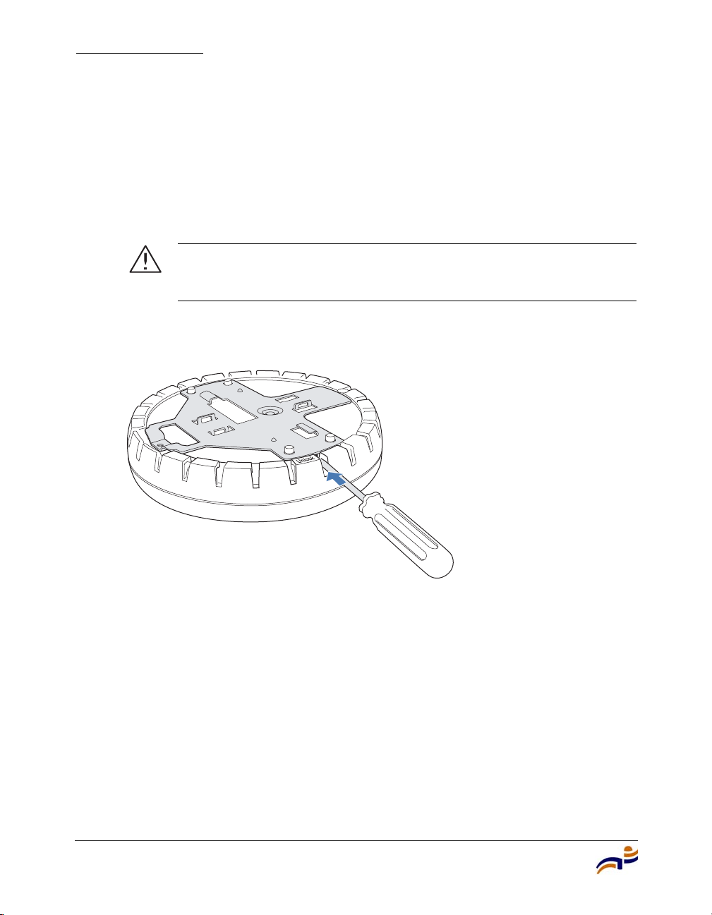
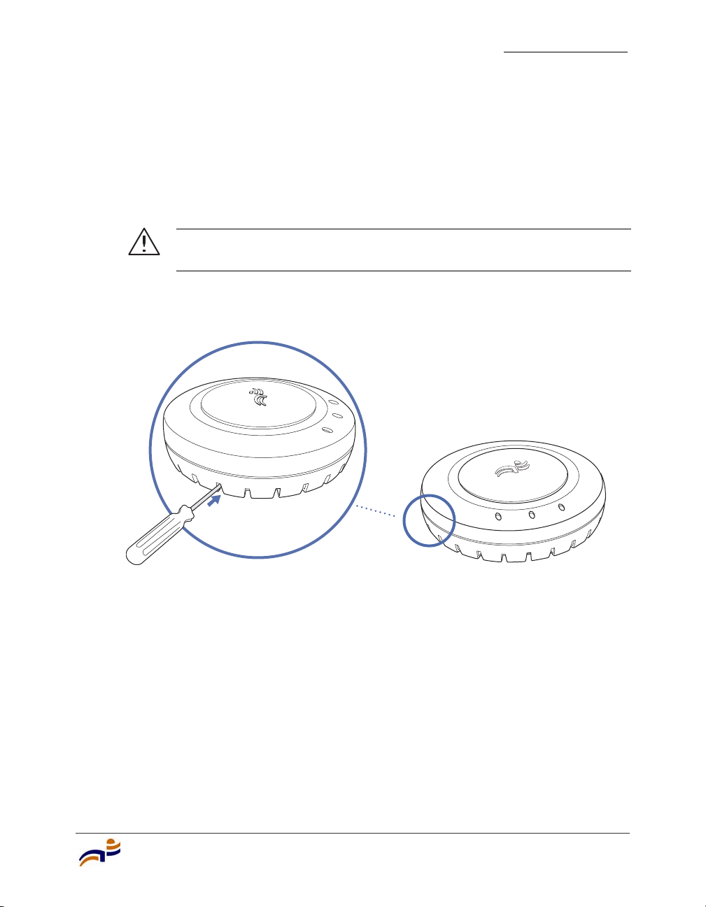
1 Unlock the universal mounting bracket from the MP access point by inserting
the 3-mm or 1/8-inch screwdriver into the Unlock hole on the MP access point
as shown in Figure 22.
Caution! To avoid damage to the MP access point’s lock mechanism
or electronic components, do not use excessive force when inserting a
tool into the Unlock or Lock hole.
Figure 22. Step 1—Unlocking the Bracket
36
840-9502-0011
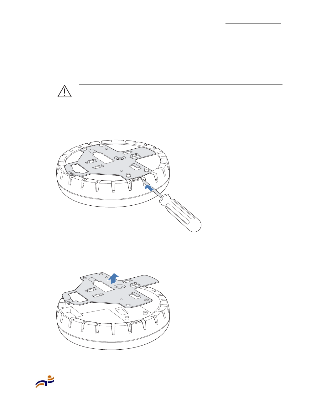
2 Remove the bracket as shown in Figure 23.
Trapeze Mobility Point Installation Guide
Page 43
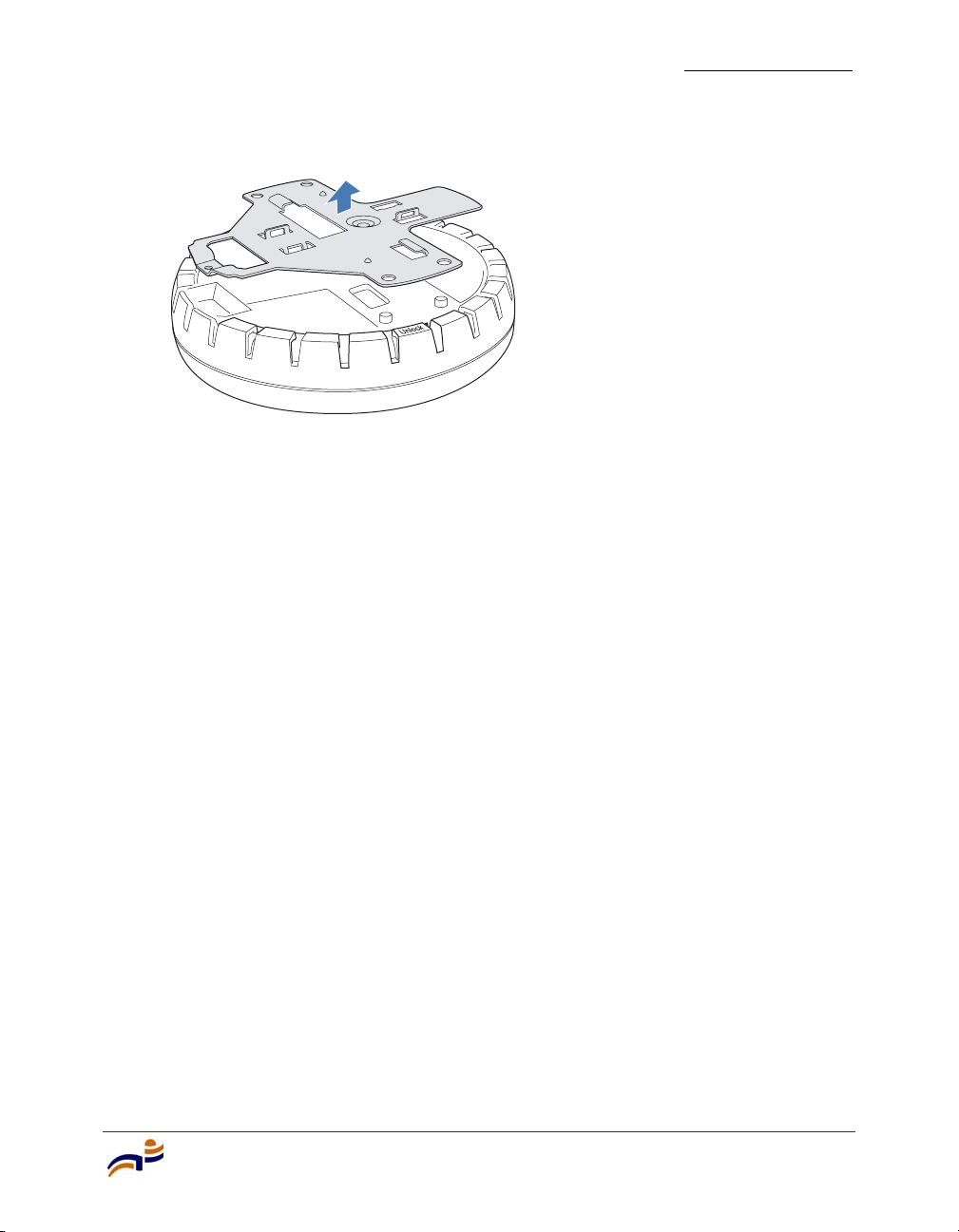
Figure 23. Step 2—Removing the Bracket
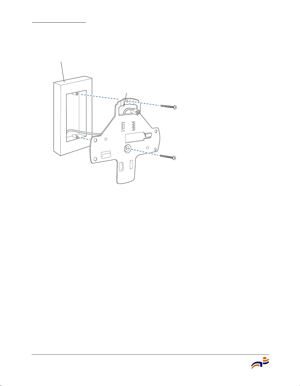
3 Attach the universal mounting bracket to the junction box as shown in
Figure 24:
a Place the universal mounting bracket against the junction box so that the
two screw holes face the junction box and align over the screw holes in
the box.
b Insert the #6-32 x 1-inch machine screws in the universal mounting
bracket’s screw holes, and use a #2 Phillips-head screwdriver to tighten
them.
Installing an MP-372
Chapter 3
840-9502-0008
Installing and Connecting an MP-372
37
Page 44
Installing an MP-372
Chapter 3
Figure 24. Step 3—Placing the Bracket on the Junction Box
Junction box
Port connector
opening
840-9502-0017
38
4 Pull the Cat 5 cable(s) about 15 cm (about 6 inches) out of the junction box
and through the port connector opening to create enough slack to insert the
cable(s) into the port connectors.
5 Insert the Cat 5 cable(s) into the connector(s):
● For a single connection, use the connector for port 1.
● For redundancy, insert one cable into each connector.
6 Install the Kensington lock, if you plan to used one.
a Loop the Kensington lock’s cable around an object that cannot be moved
or damaged by a person pulling on the cable.
b Insert the key into the Kensington lock.
c Insert the Kensington lock into the security slot on the MP.
d Rotate the key right or left to secure the lock to the MP.
e Pull on the lock to verify that it is secured to the MP.
f Remove the key.
Trapeze Mobility Point Installation Guide
Page 45
7 Lift the MP access point into place on the universal mounting bracket.
Make sure the cable feeds properly into the junction box as you lift the device,
and does not become trapped between the access point and the bracket.
8 Lock the MP access point onto the bracket by inserting the 3-mm or 1/8-inch
screwdriver into the Lock hole on the access point as shown in Figure 25.
Caution! To prevent possible damage to the MP access point, make
sure the device is fully locked onto the bracket before letting go of it.
Figure 25. Step 7—Locking the Bracket
Installing an MP-372
Chapter 3
Lock
9 To ensure that the MP access point is fully locked onto the bracket, gently pull
down on the access point and attempt to rotate it from side to side.
If the access point comes off the bracket, relock the device onto the bracket as
described in step 8 on page 39.
10 If the MP requires an external antenna, install and connect the antenna. (See
“Connecting an MP to an External Antenna” on page 49.)
11 If the other ends of the Cat 5 cable(s) are not already connected and the link
activated, go to “Connecting an MP to an MX Switch” on page 50. Otherwise,
go to “Verifying MP Health” on page 52.
Installing and Connecting an MP-372
39
840-9502-0062
Page 46

Installing an MP-372
Chapter 3
Solid Wall or Ceiling Installation
Note. The solid surface mounting option requires Cat 5 cable that does not
have strain relief, unless you plan to route the cable through a hole in the wall
or ceiling. The other options can use Cat 5 cable with or without strain relief.
(For required mounting hardware and tools, see Table 4 on page 22.)
1 Prepare holes in the wall or ceiling for the universal mounting bracket, using
the following steps:
a Place the paper mounting template over the location where you want to
install the MP access point.
b Mark the screw hole location(s).
❍ If you plan to route the Cat 5 cable externally along the wall or
ceiling, mark the locations of both the center screw hole and the
screw hole by the port connector opening.
40
❍ If you plan to route the Cat 5 cable through a hole in the wall or
ceiling, mark the location of the center screw hole only. You cannot
use the screw hole by the port connector opening if you cut a hole for
the opening.
Note. Do not mark the four holes on the edges of the bracket. (These
are the holes indicated by the dashed lines in Figure 28.) The MP access
point fits into these holes. They are not screw holes.
c Remove the template.
2 Install the drywall anchor(s):
a Hammer a drywall anchor into each hole, up to the beginning of the
threads on the anchor.
b Screw each anchor the rest of the way into its hole using a
#2 Phillips-head screwdriver.
c Remove the screw from each anchor and save the screw(s) for step 6 on
page 42.
Trapeze Mobility Point Installation Guide
Page 47
3 Unlock the universal mounting bracket from the MP access point by inserting
the 3-mm or 1/8-inch screwdriver into the Unlock hole on the MP access point
as shown in Figure 26.
Caution! To avoid damage to the MP access point’s lock mechanism
or electronic components, do not use excessive force when inserting a
tool into the Unlock or Lock hole.
Figure 26. Step 3—Unlocking the Bracket
Installing an MP-372
Chapter 3
4 Remove the bracket as shown in Figure 27.
Figure 27. Step 4—Removing the Bracket
Installing and Connecting an MP-372
840-9502-0011
840-9502-0008
41
Page 48
Installing an MP-372
Chapter 3
5 As shown in Figure 28, feed the Cat 5 cable(s) through the port connector
opening and align the universal mounting bracket over the drywall anchors so
that the two screw holes in the bracket face the drywall anchors.
6 Insert the #6 sheet metal screws into the screw holes, and tighten them to
secure the universal mounting bracket to the wall or ceiling.
(If you routed the Cat 5 cable through a hole in the wall or ceiling, insert the
screw into the center screw hole only.)
Note. Do not insert screws in the four holes on the edges of the
bracket. (These are the holes indicated by the dashed lines in
Figure 28.) The MP access point fits into these holes. They are not
screw holes.
Figure 28. Steps 5 and 6—Bracket Placement on Solid Wall or Ceiling
42
840-9502-0015
Trapeze Mobility Point Installation Guide
Page 49
Installing an MP-372
Chapter 3
7 Insert the Cat 5 cable(s) into the connector(s):
● For a single connection, use the connector for port 1.
● For redundancy, insert one cable into each connector.
8 Install the Kensington lock, if you plan to used one.
a Loop the Kensington lock’s cable around an object that cannot be moved
or damaged by a person pulling on the cable.
b Insert the key into the Kensington lock.
c Insert the Kensington lock into the security slot on the MP.
d Rotate the key right or left to secure the lock to the MP.
e Pull on the lock to verify that it is secured to the MP.
f Remove the key.
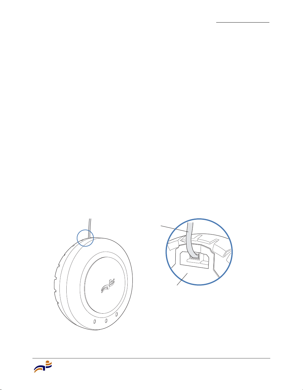
9 As shown in Figure 29, place the MP access point on the bracket, making sure
to remove any slack that occurs in the cable between the bracket and the MP
access point.
Figure 29. Step 8—Cable Placement
Cable
Universal mounting bracket
Installing and Connecting an MP-372
840-9502-0016
43
Page 50
Installing an MP-372
Chapter 3
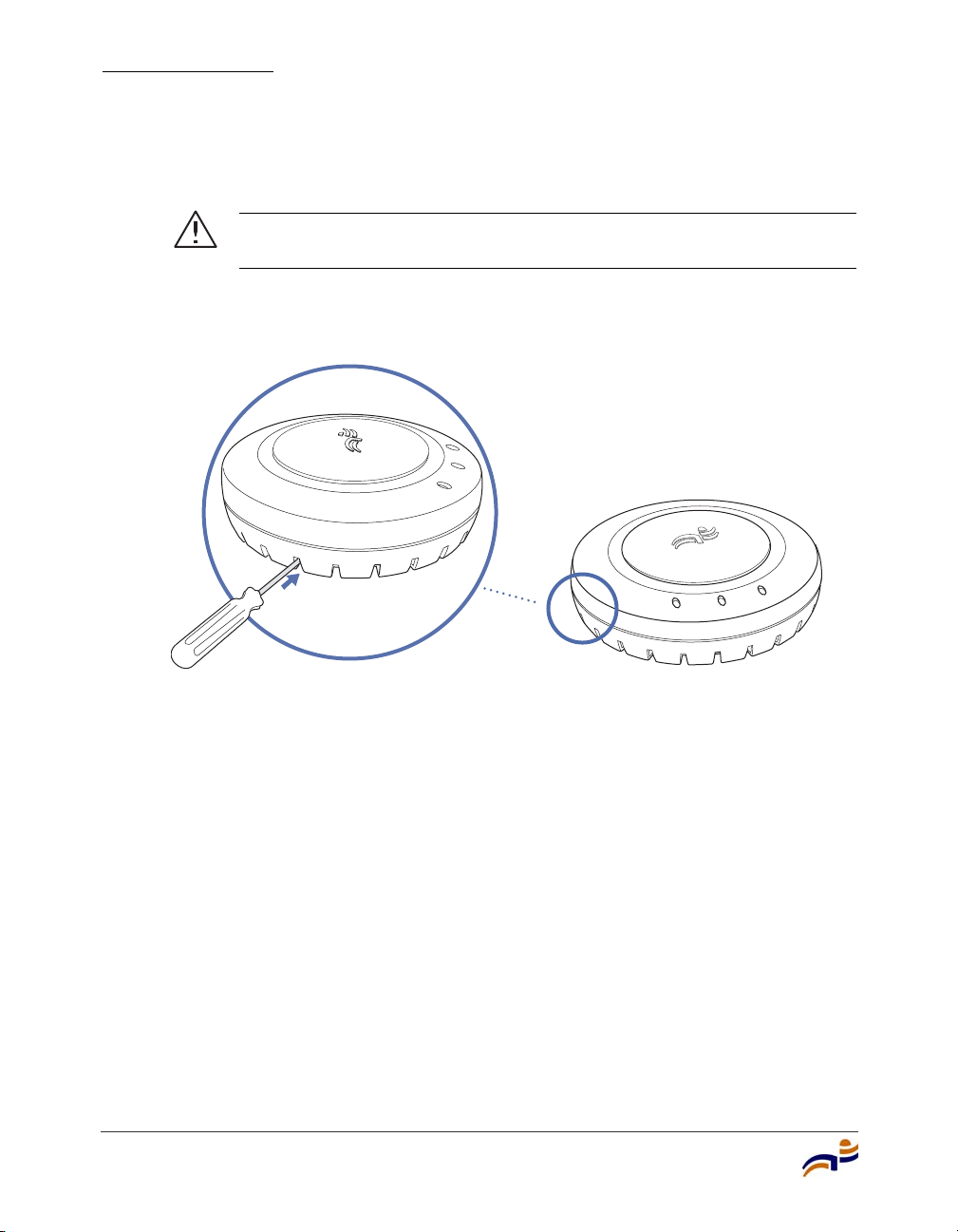
10 Lock the MP access point onto the bracket by inserting the 3-mm or 1/8-inch
screwdriver into the Lock hole on the access point as shown in Figure 30.
Caution! To prevent possible damage to the MP access point, make
sure the device is fully locked onto the bracket before letting go of it.
Figure 30. Step 9—Locking the Bracket
44
Lock
840-9502-0062
11 To ensure that the MP access point is fully locked onto the bracket, gently pull
on the access point and attempt to rotate it from side to side.
If the access point comes off the bracket, relock the device onto the bracket as
described in step 10 on page 44.
12 If the MP requires an external antenna, install and connect the antenna. (See
“Connecting an MP to an External Antenna” on page 49.)
13 If the other ends of the Cat 5 cable(s) are not already connected and the link
activated, go to “Connecting an MP to an MX Switch” on page 50. Otherwise,
go to “Verifying MP Health” on page 52.
Trapeze Mobility Point Installation Guide
Page 51
Tabletop Installation
(For required mounting hardware and tools, see Table 4 on page 22.)
1 Reverse the universal mounting bracket:
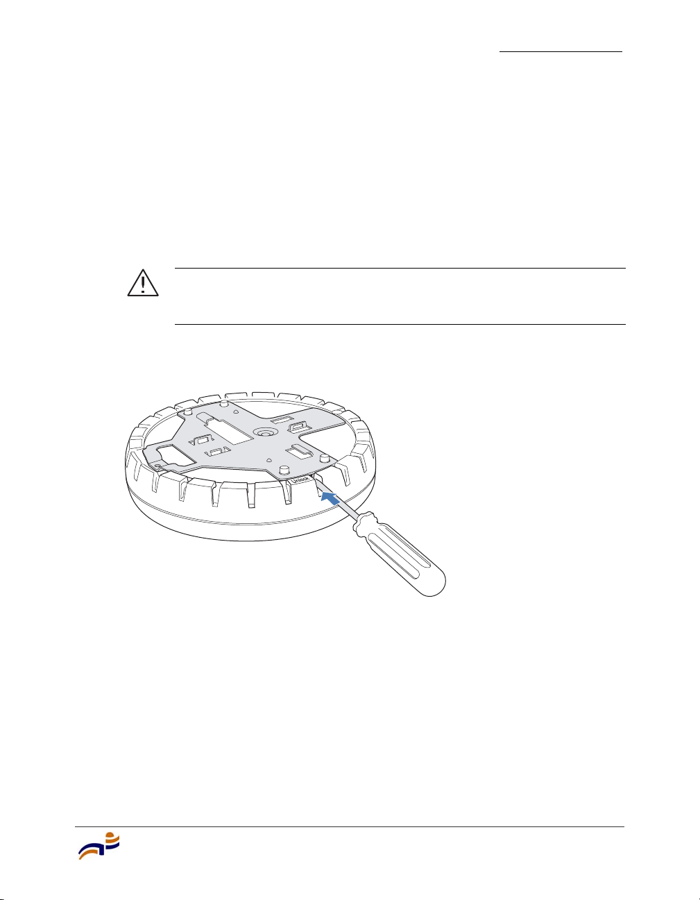
a Unlock the universal mounting bracket from the MP access point by
inserting the 3-mm or 1/8-inch screwdriver into the Unlock hole on the
MP access point as shown in Figure 31.
Caution! To avoid damage to the MP access point’s lock mechanism
or electronic components, do not use excessive force when inserting a
tool into the Unlock or Lock hole.
Figure 31. Step 1a—Unlocking the Bracket
Installing an MP-372
Chapter 3
Installing and Connecting an MP-372
840-9502-0011
45
Page 52
Installing an MP-372
Chapter 3
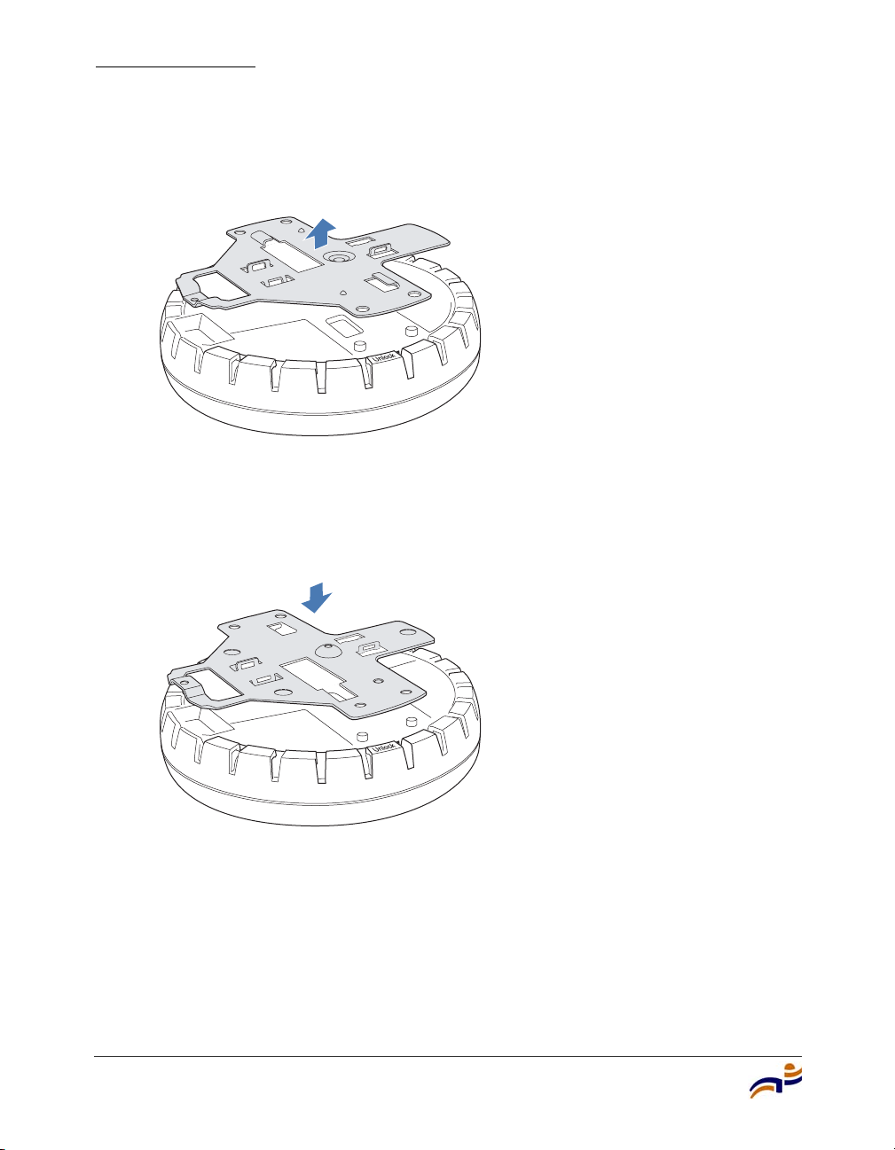
b Remove the bracket as shown in Figure 32.
Figure 32. Step 1b—Removing the Bracket
840-9502-0008
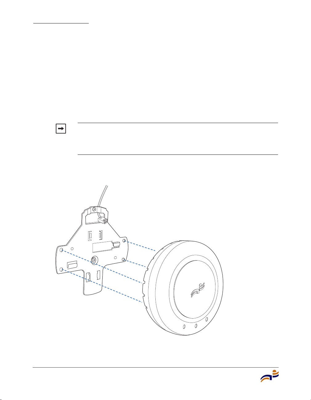
c Turn over the universal mounting bracket, then align the bracket over the
cable ports and the four mounting posts as shown in Figure 33.
Figure 33. Step 1c—Turning Over the Bracket
46
840-9502-0061
d Once the bracket is fully seated, lock the bracket onto the MP access point
by inserting the 3-mm or 1/8-inch screwdriver into the Lock hole on the
access point as shown in Figure 34.
Trapeze Mobility Point Installation Guide
Page 53
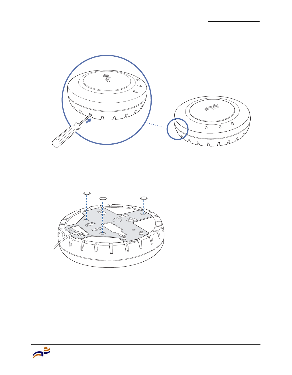
Figure 34. Step 1d—Locking the Bracket
Lock
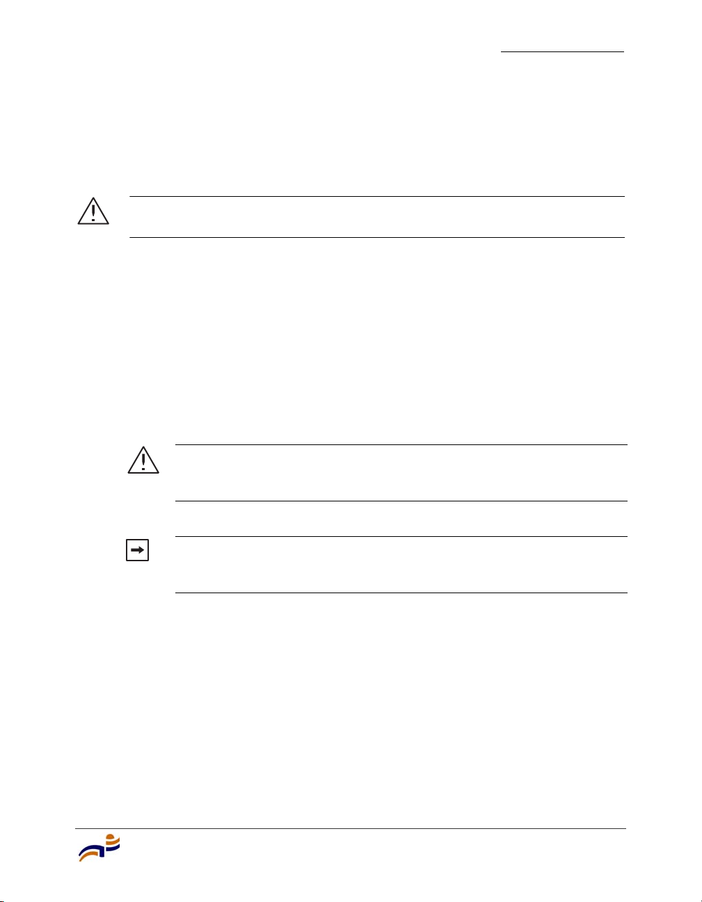
2 Attach the three rubber adhesive feet onto the universal mounting bracket, in
the three location circles, as shown in Figure 35.
Figure 35. Step 2—Installing the Rubber Feet
Installing an MP-372
Chapter 3
840-9502-0062
840-9502-0013
3 Insert the Cat 5 cable(s) into the connector(s):
● For a single connection, use the connector for port 1.
● For redundancy, insert one cable into each connector.
Installing and Connecting an MP-372
47
Page 54

Installing an MP-372
Chapter 3
4 Install the Kensington lock, if you plan to used one.
a Loop the Kensington lock’s cable around an object that cannot be moved
or damaged by a person pulling on the cable.
b Insert the key into the Kensington lock.
c Insert the Kensington lock into the security slot on the MP.
d Rotate the key right or left to secure the lock to the MP.
e Pull on the lock to verify that it is secured to the MP.
f Remove the key.
5 Place the MP access point in the desired location on the table.
6 If the MP requires an external antenna, install and connect the antenna. (See
“Connecting an MP to an External Antenna” on page 49.)
7 If the other ends of the Cat 5 cable(s) are not already connected and the link
activated, go to “Connecting an MP to an MX Switch” on page 50. Otherwise,
go to “Verifying MP Health” on page 52.
48
Trapeze Mobility Point Installation Guide
Page 55
Installing an MP-372
Connecting an MP to an External Antenna
Each radio in an MP-372 can use an optional Trapeze external antenna. To mount
the antenna, see the instructions that come with the antenna.
Caution! The external antenna must be installed at least 20 cm from the MP
access point.
To connect a mounted external antenna to an MP-372:
1 Attach the exterior antenna cable that is shipped with the antenna to the MP
external antenna connector.
Both connectors are labeled to indicate the radio type. The MP has standard
SMA connectors for attachment to the 802.11b/g antenna and to the 802.11a
antenna.
(For the location of the external antenna connectors, see Figure 2 on page 8.)
Chapter 3
Caution! The external connectors on the MP are labeled: 11B/G and
11A. Each connector is a standard SMA connector. Make sure you attach
the antenna to the correct connector.
Note. If the MP is installed in a Trapeze Networks outdoor MP
enclosure, attach the antenna cable to the lightning surge arrestor (if
installed) or the enclosure’s SMA bulkhead connector.
2 Attach the other end of the antenna cable to the antenna.
3 If the other ends of the Cat 5 cable(s) are not already connected and the link
activated, go to “Connecting an MP to an MX Switch” on page 50. Otherwise,
go to “Verifying MP Health” on page 52.
Installing and Connecting an MP-372
49
Page 56
Connecting an MP to an MX Switch
Chapter 3
Connecting an MP to an MX Switch
You can connect an MP access point directly to an MX switch or indirectly to the
switch through an intermediate Layer 2 or Layer 3 network.
● To connect the MP directly to an MX switch, configure the MX switch port as
an MP access port and use the following procedure to insert the cable into the
MX switch and verify the link.
● To connect the MP indirectly to an MX switch though the network, configure
a Distributed MP connection on the MX switch.
You can use the CLI or RingMaster to configure an MP access port or Distributed
MP connection. (See the Trapeze Mobility System Software Configuration Guide
or the Trapeze RingMaster User’s Guide.)
Figure 36 shows how to insert a Cat 5 cable into 10/100 Ethernet port on an MX
switch. Refer to this figure as you perform the procedure.
Figure 36. 10/100 Cat 5 Cable Installation
50
Ethernet port
MX-20
Mobility Exchange
Ethernet cable
(Cat 5 cable)
1 Insert a Cat 5 cable with a standard RJ-45 connector as shown in Figure 36.
MP, switch, server
or other device
For connection to an MP access point, use a straight-through cable.
Trapeze Mobility Point Installation Guide
840-9502-0058
Page 57

Connecting an MP to an MX Switch
Chapter 3
2 When the link is activated, observe the MP LED for the port on the MX
switch:
MP LED Appearance Meaning
Solid green For an MP access point’s active link, all the
following are true:
• MP access point has booted.
• MP access point has received a valid
configuration from the MX switch.
• Management link with an MP access point is
operational.
• At least one radio is enabled or is in sentry
mode.
For an MP access point’s secondary link, the
link is present.
Alternating green and
amber
MP access point is booting with an image
received from the MX switch. After the access
point boots and receives its configuration, this
LED appearance persists until a radio is enabled
or is placed in sentry mode.
Solid amber PoE is on.
Blinking amber MP is unresponsive or there is a PoE problem.
Unlit PoE is off.
Note. An MX switch’s 10/100 Ethernet ports are configured as wired network
ports by default. You or the system administrator must change the port type for
an MX port directly connected to an MP to activate the link. (See the Trapeze
Mobility Exchange Installation and Basic Configuration Guide.)
Installing and Connecting an MP-372
51
Page 58

Verifying MP Health
Chapter 3
Verifying MP Health
After you install the MP access point and enable PoE on the Ethernet cable
connected to the MP, you can easily verify the MP’s status by observing the LEDs,
particularly the health LED. (See Figure 4 on page 12.)
The health or LINK LED indicates whether the MP access point is ready for
operation.
● If the LED is green and glowing steadily, the MP has been booted
successfully by the MX switch and is ready for operation.
● If the LED is not steadily glowing green, contact the system administrator for
the MX switch or, if you are the system administrator, see Appendix A, “MP
Troubleshooting,” on page 53.
52
Trapeze Mobility Point Installation Guide
Page 59

MP Troubleshooting
After you insert a Cat 5 cable into an MP access point’s port connector and enable
PoE on the cable, observe the device’s health or LINK LED to determine the
status of the connection with the MX switch.
● If the LED is green and is glowing steadily, the MP has been booted
successfully by the MX switch and is ready for operation.
● If the LED is not steadily glowing green, see Table 5.
(For descriptions of all the LEDs, see “Status LEDs” on page 12.)
A
MP Troubleshooting
53
Page 60

Appendix A
Table 5. Health LED States
Health or LINK
LED Appearance
Diagnosis Remedy
Not solid green MP radio needs to be
enabled.
Unlit MP access point is not
receiving power.
Slowly alternating
green and amber
MP access point is booting
with an image received from
an MX switch.
Enable at least one of the radios. If
the LED is still not solid green, try
the remedy listed in this table
based on the LED’s appearance.
Check the Cat 5 cable
connection(s).
For a direct connection to an MX
switch:
• Set the port type on the MX
switch to an MP port.
• Verify that Power over Ethernet
(PoE) is enabled on the MX
switch port connected to the
MP access point.
For an indirect connection through
the network:
• Configure a Distributed MP
connection on an MX switch.
• Verify that a Trapeze-approved
PoE source is supplying power
to the MP.
Wait a few seconds for the boot
process to complete. If this LED
appearance persists, enable a radio
or place a radio in sentry mode.
Solid amber MP access point is waiting to
receive boot instructions and
a configuration file from an
MX switch.
54
Trapeze Mobility Point Installation Guide
Wait a few seconds for the boot
process to begin.
If the LED remains amber, try the
remedies for the other health LED
appearances.
If the LED still remains amber,
make sure the MP access point is
securely connected to its PoE
source and to the network or MX
switch.
Page 61

MP Technical Specifications
This appendix lists the technical specifications for the Trapeze Networks MP-372
access point. Table 6 lists the mechanical and compliance specifications. (For
detailed compliance information, see the Trapeze Regulatory Information
document.) Table 7, Table 8, and Table 9 list the radio specifications. Table 10
lists the MAC address allocation scheme.
(For specifications for the MX switch, see the Trapeze Mobility Exchange
Installation and Basic Configuration Guide.)
Note. This Listed Accessory is designed and approved to be used only with
Trapeze Networks Mobility Exchange (MX) models MX-20, MX-8, and MXR-2.
(The MX-400 switch does not directly connect to the MP.)
B
Note. The MP radios are disabled by default and can be enabled only by the
system administrator using the RingMaster management application or the MX
switch’s command-line interface (CLI).
Note. The radio frequency band, operating channels, and transmit power
depend on the country of operation specified by the system administrator using
RingMaster or the MX switch’s CLI.
MP Technical Specifications
55
Page 62

Appendix B
Table 6. MP Mechanical and Compliance Specifications
Specification Description
Size Diameter: 16.76 cm (6.6 inches)
Height: 4.69 cm (1.85 inches)
Weight Without mounting bracket: 0.35 kg (12.5 ounces)
With mounting bracket: 0.40 kg (14 ounces)
Operating Temperature 0° C to +50° C (32° F to 122° F)
Storage Temperature -20° C to +70° C (-4° F to +158° F)
Humidity 10% to 95% noncondensing
Power over Ethernet
(PoE)
42 VDC to 57 VDC (46 VDC nominal)
IEEE 802.3af (MP-341, MP-352, and MP-52)
Status indicators Health/MX and radio LEDs
(For descriptions of the LEDs, see “Status LEDs” on page 12.)
Wired network ports Two RJ-45 ports for 10/100BASE-T Ethernet and Power over
Ethernet (PoE)
Standards compliance IEEE 802.11
IEEE 802.11a
IEEE 802.11b
IEEE 802.11g
IEEE 802.3af
Safety and
electromagnetic
compliance
FCC Part 15, UL 60950
IC Part 15, CSA 22.2 N0-950, RSS-139-1 and RSS-210
ETS 300 328 (2.4 GHz) and 301 893 (5 GHz), EN 301 489-17
R&TTE Directive 1999/5/EC
TELEC, ARIB T66
GBT-15941-1995, GBT-16841-1997
LP0002
56
Trapeze Mobility Point Installation Guide
Page 63

Appendix B
Table 6. MP Mechanical and Compliance Specifications (continued)
Specification Description
Encryption Wi-Fi Protected Access (WPA)
Advanced Encryption Standard (AES)
40-bit/104-bit Wired-Equivalent Privacy (WEP)
General Power-save mode supported
Transmit power control in 1 dBm increments
Supports up to 250 clients per radio
Table 7. 802.11a Radio Specifications
Specification Description
Antenna type Integrated diversity omnidirectional
External sectorized or directional (optional)
Antenna gain Internal: 2 dBi
External:
• ANT-5060—14.5 dBi
• ANT-5120—12.5 dBi
• ANT-5180—10.8 dBi
Frequency band 5.15 GHz to 5.85 GHz based on country regulations
Operating channels Based on the country of operation specified by the system
administrator
Association rates 54 Mbps, 48 Mbps, 36 Mbps, 24 Mbps, 18 Mbps, 12 Mbps,
9 Mbps, and 6 Mbps, with automatic fallback
Modulation Orthogonal frequency division multiplexing (OFDM)
Transmit power Based on the country of operation specified by the system
administrator
MP Technical Specifications
57
Page 64

Appendix B
Table 8. 802.11b Radio Specifications
Specification Description
Antenna type Integrated diversity omnidirectional
External sectorized or directional (optional)
Antenna gain Internal: 2 dBi
External:
• ANT-1060—greater than 10 dBi
• ANT-1120—7 dBi or more
• ANT-1180—6 dBi or more
Frequency band 2.4 GHz to 2.4835 GHz based on country regulations
Operating channels Based on the country of operation specified by the system
administrator
Association rates 11 Mbps, 5.5 Mbps, 2 Mbps, and 1 Mbps, with automatic
fallback
Modulation Direct-sequence spread-spectrum (DSSS)
Transmit power Based on the country of operation specified by the system
administrator
Table 9. 802.11g Radio Specifications
Specification Description
Antenna type Integrated diversity omnidirectional
External sectorized or directional (optional)
Antenna gain Internal: 2 dBi
External:
• ANT-1060—greater than 10 dBi
• ANT-1120—7 dBi or more
• ANT-1180—6 dBi or more
Frequency band 2.4 GHz to 2.4835 GHz based on country regulations
Operating channels Based on the country of operation specified by the system
administrator
58
Trapeze Mobility Point Installation Guide
Page 65

Appendix B
Table 9. 802.11g Radio Specifications (continued)
Specification Description
Association rates 54 Mbps, 48 Mbps, 36 Mbps, 24 Mbps, 18 Mbps, 12 Mbps,
9 Mbps, and 6 Mbps, with automatic fallback
Modulation Orthogonal frequency division multiplexing (OFDM)
Transmit power Based on the country of operation specified by the system
administrator
MAC Addresses
Each MP-372 is assigned a unique block of 64 MAC addresses. Each radio has 32
MAC addresses and can therefore support up to 32 SSIDs, with one MAC address
assigned to each SSID as its BSSID.
An MP’s MAC address block is listed on a label on the back of the MP. If the MP
is already deployed and running on the network, you can display the MAC
address assignments by using the show {ap | dap} status command.
All MAC addresses on an MP are assigned based on the MP’s base MAC address,
as described in Table 10.
Table 10. MAC Address Allocations on MP-372
MP base MAC
Address
Ethernet Port
MAC Addresses
• The MP has a base MAC address. All the other addresses are
assigned based on this address.
• Ethernet port 1 equals the MP base MAC address.
• Ethernet port 2 equals the MP base MAC address + 1.
• The 802.11a radio equals the MP base MAC address + 1.
802.11a Radio
and SSID MAC
Addresses
• The BSSIDs for the SSIDs configured on the 802.11a radio end
in odd numbers. The first BSSID is equal to the MP’s base
MAC address + 1. The next BSSID is equal to the MP’s base
MAC address + 3, and so on.
• The 802.11b/g radio equals the MP base MAC address.
802.11b/g Radio
and SSID MAC
Addresses
• The BSSIDs for the SSIDs configured on the 802.11b/g radio
end in even numbers. The first BSSID is equal to the MP’s base
MAC address. The next BSSID is equal to the MP’s base MAC
address + 2, and so on.
MP Technical Specifications
59
Page 66

Appendix B
60
Trapeze Mobility Point Installation Guide
Page 67

Translated Warning Conventions and Warnings
The following warning conventions and warnings apply to this manual.
Warning Conventions
Warning! This situation or condition can cause injury.
Waarschuwing! Deze situatie of omstandigheid kan letsel veroorzaken.
Warnung! Diese Situation oder dieser Zustand kann zu Verletzungen führen.
Avertissement ! Cette situation ou cette condition peuvent provoquer des
blessures.
C
Aviso Esta situación o condición puede causar lesiones.
Translated Warning Conventions and Warnings
61
Page 68

Appendix C
Warning! High voltage. This situation or condition can cause injury due to
electric shock.
Waarschuwing! Hoog voltage. Deze situatie of omstandigheid kan letsel
veroorzaken door elektrische schokken.
Warnung! Hochspannung. Diese Situation oder dieser Zustand kann einen
Elektroschock verursachen.
Avertissement ! Haute tension. Cette situation ou cette condition peuvent
provoquer des blessures dues à des décharges électriques.
Aviso Alta tensión. Esta situación o condición puede causar lesiones por
descarga eléctrica.
Warning! Radiation. This situation or condition can cause injury due to
improper handling of fiber-optic equipment.
62
Waarschuwing! Straling. Deze situatie of omstandigheid kan letsel
veroorzaken door onjuist gebruik van glasvezelapparatuur.
Warnung! Strahlung. Diese Situation oder dieser Zustand kann durch
falschen Umgang mit glasfaserbasierten Geräten zu Verletzungen führen.
Avertissement ! Radiation. Cette situation ou cette condition peuvent
provoquer des blessures dues à une manipulation inappropriée d’appareils
équipés de fibres optiques.
Aviso Radiación. Esta situación o condición puede causar lesiones debido a un
manejo inadecuado del equipamiento de fibra óptica.
Trapeze Mobility Point Installation Guide
Page 69

Appendix C
Qualified Service Personnel Warning
Warning! Installation must be performed by qualified service personnel only.
Read and follow all warning notices and instructions marked on the product or
included in the documentation. Before installing the product, read the Trapeze
Regulatory Information document.
Waarschuwing! De installatie mag alleen worden uitgevoerd door bevoegd
onderhoudspersoneel. Het is essentieel dat u kennis neemt van alle
waarschuwingen en instructies aangebracht op het product zelf en/of
opgenomen in de documentatie. Voordat u het product installeert, dient u
Trapeze Regulatory Information in zijn geheel te hebben gelezen.
Warnung! Die Installation darf nur von einem qualifizierten
Kundendienstmitarbeiter vorgenommen werden. Lesen Sie alle Warnhinweise
und Anweisungen auf dem Produkt oder in der Dokumentation und befolgen Sie
sie. Bevor Sie das Produkt installieren, sollten Sie Trapeze Regulatory
Information vollständig lesen.
Avertissement ! L’installation doit être effectuée uniquement par des
techniciens qualifiés. Lisez et suivez toutes les notices d’avertissement et les
instructions figurant sur le produit ou comprises dans la documentation. Lisez l
Trapeze Regulatory Information avant d’installer ce produit.
Aviso Sólo puede realizar la instalación personal cualificado de asistencia
técnica. Lea y siga todas las notas de advertencia e instrucciones indicadas en
el producto o incluidas en la documentación. Antes de instalar el producto, lea
Trapeze Regulatory Information.
Translated Warning Conventions and Warnings
63
Page 70

Appendix C
Radio Safety Warnings
Warning! Do not operate the MP access point near unshielded blasting caps
or in an otherwise explosive environment unless the device has been modified
for such use by qualified personnel.
Waarschuwing! Het MP-toegangspunt mag niet worden gebruikt in de
nabijheid van onafgeschermde slaghoedjes of in een andere explosieve
omgeving tenzij het apparaat voor een dergelijk gebruik is aangepast door
bevoegd personeel.
Warnung! Die MP-Zugriffspunkte sollten nicht neben ungeschirmten
Sprengkapseln betrieben oder in einer explosiven Umgebung eingesetzt
werden. Für einen solchen Einsatz muss das Gerät von einem qualifizierten
Kundendienstmitarbeiter entsprechend angepasst werden.
Avertissement ! Le point d’accès MP ne doit pas fonctionner près de
détonateurs non blindés ou dans un autre environnement qui présent un risque
d’explosion, à moins que cet appareil n’ait été adapté en vue d’une telle
utilisation par du personnel qualifié.
64
Aviso No utilice el punto de acceso de MP cerca de detonadores no blindados
ni en un entorno explosivo, a menos que haya sido modificado el dispositivo con
ese fin por personal cualificado.
Trapeze Mobility Point Installation Guide
Page 71

Appendix C
Warning! Do not touch or move the MP access point when the antennas are
transmitting or receiving.
Waarschuwing! Het MP-toegangspunt mag niet worden aangeraakt of
verplaatst terwijl de antennes uitzenden of ontvangen.
Warnung! Berühren oder bewegen Sie den MP-Zugriffspunkt nicht, während
die Antennen senden oder empfangen.
Avertissement ! Ne touchez ni ne déplacez le point d’accès MP lorsque les
antennes sont en cours de transmission ou de réception.
Aviso No toque ni mueva el punto de acceso de MP cuando las antenas estén
transmitiendo o recibiendo señales.
Warning! Do not hold any radio device so that the antenna is very close to or
touching the face, eyes, or other exposed body part while the device's radio
antenna is transmitting.
Waarschuwing! De antenne van een apparaat dat radiogolven aan het
uitzenden is, mag nooit vlakbij of tegen het gezicht, de ogen of een andere
onbedekt deel van het lichaam worden gehouden.
Warnung! Halten Sie die drahtlosen Geräte während der Übertragung mit
der Antenne nicht nahe ans Gesicht, an die Augen oder an andere ungeschützte
Körperteile und berühren Sie die Antenne nicht.
Avertissement ! Ne maintenez pas l’antenne d’un appareil radio près du
visage, des yeux ou d’une autre partie du corps exposée ou en contact avec ces
parties du corps, lorsqu’elle est en cours de transmission.
Aviso No coloque ningún dispositivo de radio demasiado cerca de la antena ni
en contacto con la cara, los ojos u otras partes del cuerpo que estén al
descubierto mientras la antena de radio del dispositivo esté transmitiendo
señales.
Translated Warning Conventions and Warnings
65
Page 72

Appendix C
Warning! Before using a wireless device in a hazardous location, consult the
local codes, national codes, and safety directors of the location for usage
constraints.
Waarschuwing! Voordat u een draadloos apparaat gebruikt op een
gevaarlijke locatie, dient u de plaatselijke en landelijke voorschriften, en de
veiligheidsvoorschriften voor de locatie te raadplegen over eventuele
gebruiksbeperkingen.
Warnung! Bevor Sie drahtlose Geräte an einem gefährlichen Standort
einsetzen, sollten Sie die lokalen und nationalen Regelungen und
Sicherheitsbestimmungen des Standorts auf Nutzungsbeschränkungen
überprüfen.
Avertissement ! Avant d’utiliser un appareil sans fil dans un endroit
dangereux, consultez la réglementation locale et nationale ainsi que les
responsables de la sécurité de l’endroit concerné pour obtenir des informations
relatives aux conditions et aux limites d’utilisation de cet appareil.
Aviso Antes de utilizar un dispositivo inalámbrico en una ubicación peligrosa,
consulte los códigos locales y nacionales y a los responsables de seguridad de
la ubicación para conocer las restricciones de uso.
66
Trapeze Mobility Point Installation Guide
Page 73

Appendix C
Lightning Warning
Warning! Do not connect or disconnect cables or otherwise work with the MP
access point hardware during periods of lightning activity.
Waarschuwing! Tijdens onweer met bliksem mogen kabels nooit worden
aangekoppeld aan of losgekoppeld van het MP-toegangspunt of andere
werkzaamheden aan het MP-toegangspunt worden verricht.
Warnung! Verbinden und trennen Sie während eines Gewitters keine Kabel
zum MP-Zugriffspunkt und arbeiten Sie nicht damit.
Avertissement ! Ne connectez pas et ne déconnectez pas de câbles et, de
manière générale, ne travaillez pas sur le matériel du point d’accès MP lorsqu’il
y a un risque de foudre.
Aviso No conecte ni desconecte cables, ni tampoco trabaje con el hardware
del punto de acceso de MP durante una tormenta eléctrica.
Translated Warning Conventions and Warnings
67
Page 74

Appendix C
68
Trapeze Mobility Point Installation Guide
Page 75

Index
A
access point. See MP (Mobility Point)
activating an MP 50
advisory notices, explanations of 4
ANT-1060 10
ANT-1120 10
ANT-1180 10
ANT-5060 10
ANT-5120 10
ANT-5180 10
antennas, external 10
B
bracket 12
C
cable ports 9
cable requirements 20
solid surface 40
Category 5 cables 9
strain relief 40
ceiling installation
drop tiles 30
solid 40
suspended, flush tiles 24
connections
dual-homed 9
external antenna 49
LEDs 51
MX (Mobility Exchange) 50
troubleshooting 53
conventions, text and syntax 5
customer service iii
D
documentation conventions 5
documentation, product 2
drop ceiling installation 30
dual-homed connections 9
E
Ethernet
cable requirements 20
connections to an MX switch, instructions
50
connections to an MX switch, MP port
locations 9
LEDs 51
ports 9
external antenna
connections to an MP, instructions 49
external antennas 10
F
flush ceiling installation 24
H
hardware
bottom view 8
features 8
inventory 16
mounting bracket 12
required, list of 22
top view 8
Index
69
Page 76

health LED
description 13
troubleshooting with 53
verifying MP health with 52
I
installation
junction box 36
MP 15, 22
requirements 18
requirements, tools 22
solid surface 40
suspended ceilings 30
suspended ceilings, flush tiles 24
tabletop 45
T-bar ceilings. See suspended ceilings
warnings, cables 20
warnings, radio 19
warnings, service 7
warnings, translations 61
IP addresses 59
M
MAC addresses 59
manuals, product 2
Mobility Exchange. See MX
Mobility Point. See MP
model numbers
external antennas 10
mounting bracket 12
mounting options 12
MP (Mobility Point)
description of 7
installation 15, 22
specifications 55
troubleshooting 53
warnings 61
MX (Mobility Exchange)
connections 14, 50
MP LEDs 51
recommendation 18
N
J
junction box installation 36
K
Kensington security slot 12
L
LEDs 12
health 13, 52, 53
MP (on MX) 51
radio 13
links
dual-homed 9
LEDs 51
MP 51
troubleshooting 53
70
network plan, RingMaster 18
P
PoE (Power over Ethernet)
dual-homed connections 9
pin signals 21
specifications 56
use with Trapeze devices only 18
ports 9
product documentation 2
R
radio LEDs 13
radios
default state 7
health 53
radio LEDs 13
specifications 55
status 13
Trapeze Mobility Point Installation Guide
Page 77

troubleshooting 53
warnings 19
redundancy 9
requirements 18
cables 20
hardware 22
RingMaster
wall installation recommendations 19
work order 18
RJ-45s 9
S
safety notices, explanations of 4
solid surface installation 40
specifications 55
status LEDs. See LEDs
status lights. See LEDs
suspended ceilings, installation
drop tiles 30
flush tiles 24
switch. See MX (Mobility Exchange)
syntax conventions 5
T
W
wall installation
junction box 36
recommendations 19
solid 40
warnings
cable 20
installation 7
radio 19
translations 61
work order, RingMaster 18
tabletop installation 45
TAC (Technical Assistance Center) iii
T-bar ceilings. See suspended ceilings
Technical Assistance Center iii
technical specifications 55
technical support iii
tools 22
translated warnings 61
Trapeze customer service iii
Trapeze Networks Mobility System 1
troubleshooting 53
U
universal mounting bracket 12
unpacking an MP 16
Index
71
Page 78

72
Trapeze Mobility Point Installation Guide
 Loading...