

5.8 GHz Wireless
Audio/Video Sender

Contents
1.Important Safety Information.......................................1
2.Package Content........................................................2
3.Panel Control And Function......................................... 3
4.Setup Guide...............................................................4
5.Orient Transmitter/Receiver for optimal performance.....5
1.Important Safety Information
To prevent fire or shock hazard, do not expose this product to rain and
moisture. For example: do not use near a bathtub, washbowl, kitchen
sink, or laundry tub, in a wet basement, or nearby a swimming pool. To
avoid electric shock, do not take apart this product, provided as an
accessory. This product should be operated only under power supply.
Do not overload wall outlets and extension outlets as this can result in
the risk of fire or electric shock.
□ NOTE:
This equipment has been tested and found to comply with the
limits regulated by FCC and CE. These limits are designed to
provide reasonable protection against harmful interference in a
residential installation. This equipment generates, uses and can
radiate radio frequency energy and, if not installed and used in
accordance with the instruction, may cause harmful interference
to radio communications. The change or modifications no
expressly approved by the party responsible for compliance could
void the user's authority to operate the equipment. To comply with
the FCC RF exposure compliance requirements, no change to the
antenna or the device is permitted. Any change to the antenna or
the device could result in the device exceeding the RF exposure
requirements and void user's authority to operate the device.
1
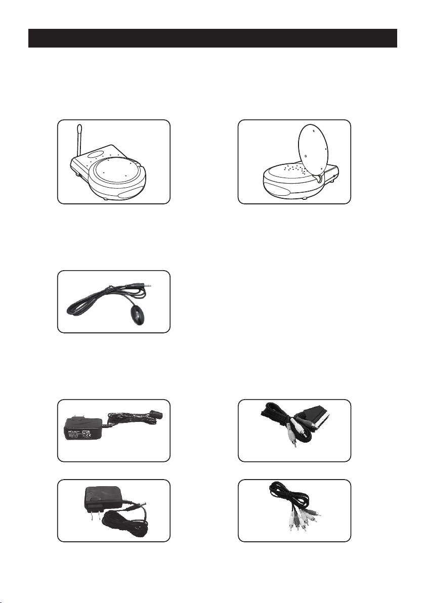
2.Package Contents
Check to make sure that all units shown as below are enclosed.
If something missed, please contact your dealer.
1. 5.8GHz Transmitter x 1
UHF:433.92MHz
3. IR Cable LED x 1
Power Adapters
4.
(9V/500mA) x 2
2. 5.8GHz Receiver x 1
5. Cables x 2
EUROPE Type
USA Ty pe
EUROPE Type( RCA to S CAR T)
USA Ty pe( RCA to R CA)
2

2.Package Contents3.Panel Control and Function
Transmitter/Receiver
1
2
4
3
ID Code
ON
1 2 3
ON
1 2 3
ID 1 ID 4ID 3
ON
1 2 3
ID 6ID 5 ID 8ID 7
ON
1 2 3
ID 2
ON
1 2 3
ON
1 2 3
ON
1 2 3
ON
1 2 3
9
5
8
7
1. UHF antenna
2. ON/OFF switch
3. Power indicator/IR windows
4. IR mouse jack (transmitter only)
Channel selection button to find optimal reception
(receiver only)
5. Power adapter jack
6. DIP switch for ID code, the transmitter and receiver
must to be configured as the same ID code.
7. Video jack, (yellow), input from source AV equipment
8. Audio jack, right (red), input from source AV equipment
9. Audio jack, left (white), input from source AV equipment
ON
1 2 3
6
3

2.Package Contents4.Setup Guide
To enjoy a life of wireless video and audio, just connect the
transmitter to whatever A/V source you like and connect the
receiver to a TV, monitor or speaker in another location.
2.Package Contents
Not e: Make sure the ON/OFF swi tch is in the OFF pos ition bef ore co nne ction「 」
Transmitter
1. Connect one end of the RCA cable
(or scart cable) to the RCA jacks,
and connect the other end to a
source device as well.
2. Connect the DC plug of the adapter
to the DC jack, and connect the power
supply to an outlet.
3. Keep the IR window oriented toward
the source AV equipment, or
alternatively use the IR Mouse to remotely
control it.
Tra ns mit te r
IR M ous e
Receiver
OUT
To AV Equipment
1. Connect one end of the RCA cable
(or scart cable) to the RCA jacks,
and connect the other end to a
TV (or monitor, speakers) on which
you like to enjoy a program.
Remot e
Contr oller
2. Connect the DC plug of the adapter
to the DC jack, and connect the power
supply to an outlet.
Receiver
3. Keep the IR window oriented toward
your remote controller.
* A complete set-up procedure consists of:
1. Press “CH” button on receiver, receiver
will make transmitter switch to the same
channel.
2. Make sure the ID on transmitter and receiver
is identical (For example, as exhibit
ON
Transmitter: Receiver: )
1 2 3
ID 1
ON
1 2 3
ID 1
IN
To TV
whenever there is problem with installation, please implement the set-up
procedure again.
4

5.Orient Transmitter/Receiver for optimal performance
For optimal performance, both the audio/video and remote
control antennas should be carefully oriented as described
below. For maximum transmitting range, try to minimize
obstacles (e.g. your TV or other electronics, large furniture)
where between the transmitter and receiver.
Orients the 5.8GHz A/V Antennas
The system delivers high-quality
5.8GH z Antenn a
5.8GH z Antenn a
audio and video by using directional
antennas, which must be oriented
to get the best results.
The antennas are designed to
be able to rotate in almost any
direction.
Tra ns mit te r
Fig. 1
Recei ver
In most situations, the convex
of the antennas on both the
transmitter and receiver should be facing one another and
perpendicular (at a right angle) to an imaginary line drawn
between the two units. Two examples are shown as Fig.1,
Fig.2. Since all homes are different, for optimal reception,
additional alignment may be necessary.
If the transmitter and receiver are less than 10 feet apart,
suggest to lie the antennas on their casings since the distance
is so short.
5.8GH z Antenn a
Tra ns mit te r
Fig. 2
5.8GH z Antenn a
Re ceive r
5

Orients the UHF Antennas
In order to obtain optimal performance of the remote control
extender, the remote control antennas should also be oriented
at a right angle to an imaginary line drawn between the
transmitter and receiver.
If your remote control extender is not working satisfactorily,
rotate the remote control antenna on either the transmitter or
receiver 90 degrees so that it is still perpendicular to the path
between the units.(See Fig.3)
IF you notice improved performance, keep this orientation.
Rotating the antenna on both units should have no effect.
UH F A nt enn a
UH F A nt enn a
Tra ns mit te r
Fig. 3
Re cei ve r
6

408-000639-00
 Loading...